1
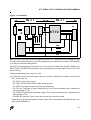
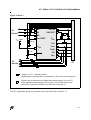
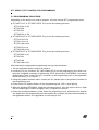
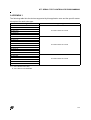
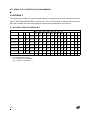
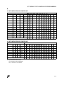
AN987 APPLICATION NOTE ST7 SERIAL TEST CONTROLLER PROGRAMMING by Microcontroller Division Applications INTRODUCTION This application note describes: – The advantages of Serial Test Controller Programming (STCP) vs. programming using an EPROM programming board (EPB) (see Section 2.1). – How to implement Serial Test Controller Programming targeting most of the ST7 general purpose microcontrollers (see Section 2.2). These devices include all parts supported by the ST7 starter kits and ST7 EPBs in the MDT1, MDT2 and MDT4 tool families (see the supported device list in APPENDIX 1). Note: In this application note, the term “programming tool” refers to either the EPBs or the starter kits. 1 PROGRAMMING TECHNIQUES There are two possible ways of programming an ST7 device: ■ Using a programming tool. In this case, the device is first plugged on the programming board and then programmed. Then, the part is soldered or plugged into a socket on the user board. This can be done using any of the following ST7 programming tools: – ST7 Starter Kit – ST7 EPB (EPROM Programming Board) – ST7 Gang Programmer For further details about the above tools, please refer to the user manual supplied with these devices. ■ Using a Serial Test Controller Programming (STCP) tool. This technique allows a device to be directly programmed on the user board. This is a two-step procedure where first the board is first manufactured with a blank ST7, and afterwards the chip is programmed using a programming tool (Starter Kit or EPB). This application note describes the STCP method only. AN987/1000 1/10 1 ST7 SERIAL TEST CONTROLLER PROGRAMMING 2 SERIAL TEST CONTROLLER PROGRAMMING 2.1 ADVANTAGES The advantages of STCP are numerous: ■ Time to market To reduce manufacturing cycle times, a user board can be designed to be generic, supporting several functions. These functions can be enabled or disabled by software according to customer requirements. In this case, STCP allows application boards to be manufactured in one shot and programmed with different functions according to customer needs and orders. ■ Cost reduction Software updates may be necessary in some cases because of a bug correction or a newly implemented feature. The STCP is a flexible and painless way of performing such modifications and at a lower cost. There is no need to add any sockets to the board or to unsolder and change components in order to upgrade the application. ■ Security Because STCP offers an easy way to customise the user’s program, or part of it, it can be used to insert different key codes for each board. This could be used, for example, in a door lock system. ■ Flexibility For example, STCP can be used to allow calibration procedures to be performed directly in the field. 2.2 USER BOARD SPECIFICATION The user has to design his layout in order to support two modes: programming mode and user mode. Figure 1. shows the user board divided into two blocks: ■ Block 1: Includes all the components that play a role during programming mode: – Connector J1, which links the user board to the programming tool. – The ST72 MCU, which is the device to be programmed. – Jumpers W1 to Wn, whose purpose is to isolate the pins used for programming the ST72 from the other components in Block 2. In some application configurations, isolation resistors (47 kΩ) can be used instead of jumpers. ■ Block 2: This block consists of all the other components soldered on the user board. 2/10 2 ST7 SERIAL TEST CONTROLLER PROGRAMMING Figure 1. User Board % OR FN % OR FN - 67 :Q : Now, let’s define the pins used for programming the ST7. These pins are put together in the W1 connector implemented in all the ST programming tool boards (see Section 3 APPENDIX 1 for the pin connector assignment). All the ST7 programming tools referred to in this note (ST7 starter kits and ST7 EPBs in the MDT1, MDT3 and MDT4 tool families) use a programming technique called JTAG (Joint Test Action Group). These programming tools control 11 pins: ■ 5 JTAG pins and 3 test mode pins, which are used for loading the software code into the ST7. These pins are: – Pin TCK: the test clock (input), – Pin TMS: the Test Mode Select (input, weak pull-up), – Pin TRST0: the Reset (Input, weak pull-up, active low) – Pin TDI: the Test Data In (input, weak pull-up). This is the serial data input, sampled on the rising edge of TCK. – Pin TDO: the Test Data Out (tri-state output). This is the serial data output, updated on the falling edge of TCK. – Pins M0, M1 and M2: These 3 pins are used to force the test modes. Depending on the device selected, these 8 pins will be associated with different pin numbers (see APPENDIX 1). 3/10 ST7 SERIAL TEST CONTROLLER PROGRAMMING If these pins need to be tied to VDD or VSS, or if they are used by the user’s application, they must be isolated from the user circuitry during programming. To do so, a jumper can be added for each of the eight pins (see Figure 2.). Note: Isolation resistors (47 kΩ) can be used instead of jumpers only if these pins are used by the application as input (without Pull-up, without pull-down, or analog input configuration). ■ 3 system pins, VPP/TEST, RESET and OSCIN, which must be connected as follows: – The VPP/TEST pin must not be directly connected to GND/VSS on the application board in order to avoid any conflict with the programming voltage. This pin should be pulled down by a 10 kΩ resistor (see Figure 2.). – The RESET pin controls the entry into programming mode. This pin must be connected to a 10 kΩ pull-up resistor and a 1 nF capacitor connected to GND (see Figure 2.) to avoid any direct connections to VSS. This pin can be connected to a 47 kΩ isolation resistor if an external reset is provided by the application board. – The OSCIN pin synchronizes the programming operation using a clock generated by the programming tool. The OSCIN pin can be directly connected to the J1 connector. No isolation is needed as long as a quartz crystal or ceramic resonator is used in the application. If an external clock generator is used in the application, it must be disconnected during STC programming. Note: The OSCOUT pin does not need to be disconnected during the programming phase as long as a crystal, a ceramic resonator or an external clock source is used to drive the internal oscillator (user mode only). ■ The VDD and VSS power supply pins. The use of the VDD connection is optional, depending on whether the application board supply can be disconnected or not. If the application board supply is disconnected, the chip can be supplied through the programming tool (as long as the total current load does not exceed 100 mA and the capacitive load is less than 50 µF). In this case, only 1 jumper needs to be added in order to disconnect the VPP pin from the user circuitry during the programming sequence. No jumper is needed for VSS (see Figure 2.). If you want to use the application board power supply, its voltage must be 5 V, so that logic levels are compatible with those of the programming tool. Note: In any case, the ground from the application board and the ground from the programming tool must be connected together (see Figure 2.). 4/10 ST7 SERIAL TEST CONTROLLER PROGRAMMING Figure 2. Block 1 To block2 M0 OSCIN M1 OSCOUT M2 VDD appli VPP/TEST 10 kΩ VSS Tck VDD Tms Trst0 10 kΩ Reset Tdi Tdo To block2 J1 Jumper or 47 kΩ isolation resistor (depending on the application configuration, refer to the note on page 3). Jumper use to disconnect the Application board supply if it is not 5 V. If the application board supply can be used, remove this jumper and remove the connection between pin VDD and connector J1. The ST7 programming tool is connected to the user board via connector J1. 5/10 ST7 SERIAL TEST CONTROLLER PROGRAMMING 2.3 PROGRAMMING PROCEDURE Depending on the device you need to program, use one of these ST7 programming tools: ■ ST7 MDT1-KIT or ST7 MDT1-EPB. They cover the following devices: – ST72101G1 or G2 – ST72212G2 – ST72213G1 – ST72251G1 or G2 ■ ST7 MDT2-KIT or ST7 MDT4-EPB. They cover the following devices: – ST72121J2 or J4 – ST72311J2 or J4 – ST72311N2 or N4 – ST72331J2 or J4 – ST72331N2 or N4 ■ ST7 MDT4-KIT or ST7 MDT4-EPB. They cover the following devices: – ST72272K2 or K4 – ST72372J4 – ST72371N4 – ST72671N4 or N6 After selecting the appropriate programming tool, proceed as follows: 1. On the application board, remove all jumpers. 2. Locate the 16 pin connector W1 (8x2 header HE10) on the programming tool which contains the 12 signals necessary for performing STCP (see Section 3 APPENDIX 1 for the pin identification).Then connect the W1 connector of the programming tool to the application board connector (J1 in Figure 1.). 3. Using the parallel interface cable, connect the PC parallel port to the parallel connector of the programming tool. 4. Power on the PC and the board. On the programming tool, LED 1 must light up. 5. Start the Windows EPROMer, target the programming tool, then the correct device. Open the file containing the code to program. And... program your device! 6. Close the operating software, power down the programming tool, disconnect the application board from the programming tool and replace any jumpers that were disconnected on the application board. Your application is now ready to run! 6/10 ST7 SERIAL TEST CONTROLLER PROGRAMMING 3 APPENDIX 1 The following table lists the devices supported by this application note and the specific starter kit required for each sales type. Sales Type ST72x101G1 ST72x101G2 ST72x212G2 ST72x213G1 ST72x251G1 ST72x251G2 ST72x121J2 ST72x121J4 ST72x311J2 ST72x311J4 ST72x311N2 ST72x311N4 ST72x331J2 ST72x331J4 ST72x331N2 ST72x331N4 ST72x272K2 ST72x272K4 ST72x371N4 ST72x372J4 ST72x671N4 ST72x671N6 Starter Kit supporting the device ST7 MDT1 Starter kit or EPB ST7 MDT2 Starter kit or EPB ST7 MDT4 Starter kit or EPB x = T, if the device is an OTP, E, if the device is an EPROM. 7/10 ST7 SERIAL TEST CONTROLLER PROGRAMMING 4 APPENDIX 2 This appendix provides the required information for programming a device supported by the MDT1, MDT2 and MDT4 EPBs or starter kits. The five JTAG pins and three test mode pins (M0, M1 and M2) with their associated pin numbers are specified for each device. 4.1 ST7 MDT1 EPB OR STARTER KIT ST7 Device Sales type Pin Numbers EPROM E2 RAM Package JTDI JTCK JTRST JTMS JTDO M2 PA3 PA2 PA1 PA0 PC3 PB2 PB1 PB0 M1 M0 Vpp Reset Oscin Vdd Vss ST72x101G1 4K - 256 SO28 SDIP32 22 26 23 27 24 28 25 29 14 16 9 11 10 12 11 13 26 30 1 1 2 2 28 32 27 31 ST72x101G2 8K - 256 SO28 SDIP32 22 26 23 27 24 28 25 29 14 16 9 11 10 12 11 13 26 30 1 1 2 2 28 32 27 31 ST72x212G2 8K - 256 SO28 SDIP32 22 26 23 27 24 28 25 29 14 16 9 11 10 12 11 13 26 30 1 1 2 2 28 32 27 31 ST72x213G1 4K - 256 SO28 SDIP32 22 26 23 27 24 28 25 29 14 16 9 11 10 12 11 13 26 30 1 1 2 2 28 32 27 31 ST72x251G1 4K - 256 SO28 SDIP32 22 26 23 27 24 28 25 29 14 16 9 11 10 12 11 13 26 30 1 1 2 2 28 32 27 31 ST72x251G2 8K - 256 SO28 SDIP32 22 26 23 27 24 28 25 29 14 16 9 11 10 12 11 13 26 30 1 1 2 2 28 32 27 31 5 1 9 3 7 12 10 8 16 4 2 Programming tool W1 connector x = T, if the device is an OTP, E, if the device is an EPROM, N.C., means not connected. 8/10 N.C 15 ST7 SERIAL TEST CONTROLLER PROGRAMMING 4.2 ST7 MDT2 EPB OR STARTER KIT ST7 Device Pin Numbers JTDI JTCK JTRST JTMS JTDO M2 PA6 36 29 PA5 35 28 PA4 34 27 PA3 31 24 PB2 PB1 PB0 4 3 2 41 40 39 M1 Sales type EPROM E2 RAM Package ST72x121J2 8K - 384 TQFP44 SDIP42 PA7 37 30 ST72x121J4 16K - 512 TQFP44 SDIP42 37 30 36 29 35 28 34 27 31 24 4 41 3 40 ST72x311J2 8K - 384 TQFP44 SDIP42 37 30 36 29 35 28 34 27 31 24 4 41 ST72x311J4 16K - 512 TQFP44 SDIP42 37 30 36 29 35 28 34 27 31 24 ST72x311N2 8K - 384 TQFP64 SDIP56 52 40 51 39 50 38 49 37 ST72x311N4 16K - 512 TQFP64 SDIP56 52 40 51 39 50 38 ST72x331J2 8K 256 384 TQFP44 SDIP42 37 30 36 29 ST72x331J4 16K 256 512 TQFP44 SDIP42 37 30 ST72x331N2 8K 256 384 TQFP64 SDIP56 ST72x331N4 16K 256 512 TQFP64 SDIP56 M0 Vpp Reset Oscin 38 31 39 32 42 35 2 39 38 31 39 32 42 35 3 40 2 39 38 31 39 32 42 35 4 41 3 40 2 39 38 31 39 32 42 35 46 34 7 55 6 54 5 53 53 41 54 42 59 45 49 37 46 34 7 55 6 54 5 53 53 41 54 42 59 45 35 28 34 27 31 24 4 41 3 40 2 39 38 31 39 32 42 35 36 29 35 28 34 27 31 24 4 41 3 40 2 39 38 31 39 32 42 35 52 40 51 39 50 38 49 37 46 34 7 55 6 54 5 53 53 41 54 42 59 45 52 40 51 39 50 38 49 37 46 34 7 55 6 54 5 53 53 41 54 42 59 45 5 1 9 3 7 12 10 8 16 4 2 Programming tool W1 connector 4.3 ST7 MDT4 EPB OR STARTER KIT ST7 Device Sales type Pin Numbers EPROM E2 RAM Package JTDI JTCK JTRST JTMS JTDO M2 PA7 PA6 PA5 PA4 M1 M0 PC6 DA3 DA2 DA1 Vpp Reset Oscin Vdd Vss ST72x272K2 8K - 384 SO34 SDIP32 29 27 30 28 31 29 32 30 25 24 3 3 2 2 1 1 34 32 33 31 28 26 8 8 7 7 ST72x272K2 16K - 512 SO34 SDIP32 29 27 30 28 31 29 32 30 25 24 3 3 2 2 1 1 34 32 33 31 28 26 8 8 7 7 ST72x371N4 16K - 512 TQFP64 SDIP56 28 46 29 47 30 48 31 49 20 38 43 3 42 2 41 1 40 56 38 54 27 45 11 31 9 29 ST72x372J4 16K - 512 SDIP42 34 35 36 37 31 2 1 42 41 40 33 25 23 TQFP64 SDIP56 TQFP64 SDIP56 28 46 28 46 29 47 29 47 30 48 30 48 31 49 31 49 20 38 20 38 43 3 43 3 42 2 42 2 41 1 41 1 40 56 40 56 38 54 38 54 27 45 27 45 11 31 11 31 9 29 9 29 5 1 9 3 7 12 10 8 16 4 2 N.C 15 ST72x671N4 16K - 512 ST72x671N6 32K - 1K Programming tool W1 connector x = T, if the device is an OTP, E, if the device is an EPROM, N.C., means not connected. 9/10 ST7 SERIAL TEST CONTROLLER PROGRAMMING THE PRESENT NOTE WHICH IS FOR GUIDANCE ONLY AIMS AT PROVIDING CUSTOMERS WITH INFORMATION REGARDING THEIR PRODUCTS IN ORDER FOR THEM TO SAVE TIME. AS A RESULT, STMICROELECTRONICS SHALL NOT BE HELD LIABLE FOR ANY DIRECT, INDIRECT OR CONSEQUENTIAL DAMAGES WITH RESPECT TO ANY CLAIMS ARISING FROM THE CONTENT OF SUCH A NOTE AND/OR THE USE MADE BY CUSTOMERS OF THE INFORMATION CONTAINED HEREIN IN CONNEXION WITH THEIR PRODUCTS." Information furnished is believed to be accurate and reliable. However, STMicroelectronics assumes no responsibility for the consequences of use of such information nor for any infringement of patents or other rights of third parties which may result from its use. No license is granted by implication or otherwise under any patent or patent rights of STMicroelectronics. Specifications mentioned in this publication are subject to change without notice. This publication supersedes and replaces all information previously supplied. STMicroelectronics products are not authorized for use as critical components in life support devices or systems without the express written approval of STMicroelectronics. The ST logo is a registered trademark of STMicroelectronics 2000 STMicroelectronics - All Rights Reserved. Purchase of I2C Components by STMicroelectronics conveys a license under the Philips I2C Patent. Rights to use these components in an I2C system is granted provided that the system conforms to the I2C Standard Specification as defined by Philips. STMicroelectronics Group of Companies Australia - Brazil - China - Finland - France - Germany - Hong Kong - India - Italy - Japan - Malaysia - Malta - Morocco - Singapore - Spain Sweden - Switzerland - United Kingdom - U.S.A. http://www.st.com 10/10