1
UART TFT LCD user manual
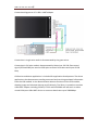
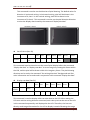
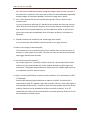
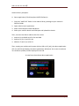
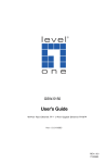
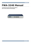
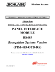
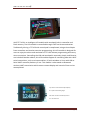
UART TFT LCD is an intelligent LCD module with touchpad, built‐in controller and flash memory. The LCD module is controlled through UART serial communication. Traditionally, driving a TFT LCD with a touchpad is complicated, using at least 24pins from controllers and involve extensive programming, this LCD module is designed for users to enjoy the colour and resolution of TFT LCD without programming and messy wires connection. Controlling the LCD and touchpad is extremely simple, and libraries are included. Besides arduino, this LCD module support all controlling host with UART serial transmission, such as microcontrollers, PC with windows or linux with USB to Serial UART controller, Rasberry Pi etc. This module is also tested on Bluetooth wireless UART transmission which means remote display and control of host can be accomplished. Top: UART TFT LCD controlled by Raspberry Pi as system information gadget Left: UART TFT LCD controlled by arduino as a color LCD clock
Page 1
UART TFT LCD user manual
Features: On board 2.8inch 320x240 TFT LCD module supporting 65k color On board 32MBit serial flash for storing fonts, images and icons. USB 1.1 connection with software for Windows to import images to serial flash for display Built in fonts with 10 different sizes with extended ASCII characters, extra user’s fonts can be downloaded to flash memory via USB On screen touchpad and on board 12bit touchpad controller, touch coordinates can be retrieved and sent to host via UART for input processing. Support single wire mode(only one wire data connection is required) or full wire mode (two wire data connection is required). Auxiliary pin for full LCD control (LCD busy, Touchpad Interrupt, LCD reset) Wireless booth module upgrade reserved on the PCB, remote display and control of host can be achieved using Bluetooth wireless UART transmission and one wire data mode. Only send simple command to display text, image or to control the LCD. No low level LCD control and data transfer are required Support advanced function like drawing image and bitmap character directly via UART data transmission. LCD brightness, orientation, writing direction can be fully controlled UART baud rate can be set through software, up to 500000bps. UART data which is not sent to the LCD will be bypassed to other device, so that you can still use arduino’s only UART to communicate with other device. On board input buffer, all inputs are tested 5V/3V tolerant, no 5V>3V conversion is required. Multiple LCDs can be displayed simultaneously by the same host by joining the host UART Transmit signal Page 2
UART TFT LCD user manual
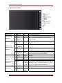
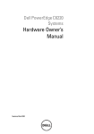
Hardware information . Interface set Pins Signals UART Bypass (optional) Full wire LCD control interface (optional) Functional Description 1 GND Power Ground 2 UART Bypass Output UART data output bypassed when LCD Select signal is LOW 3 Reset Input 4 Touchpad Interrupt Output LOW when touchpad is pressed, otherwise HIGH 5 LCD Busy Output LOW when LCD is busy, otherwise HIGH. Instructions should not be sent to LCD when LOW
6 LCD Select Input 7 GND Power Ground UART LCD control 8 LCD Tx interface/ 9 LCD Rx external wireless 10 3.3V interface Power input I/O Reset the device, active low, internally pull up to 3.3V Enable the LCD start receiving data from Rx, active HIGH (required for full wire interface) Output UART data transmitted by LCD Input UART data received by LCD Power 3.3V input, or 3v3 output when 5V is connected Input/O Warning: never try to connect 5V source to this utput input, even though there is protection. 11 Gnd Power Ground 12 5V Power 5V input Input Page 3
UART TFT LCD user manual
Hardware specifications:
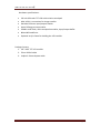
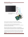
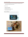
2.8 inch 65k color TFT LCD with resistive touchpad Mini USB 1.1 connection for image transfer Standard 2.54mm input/output header Atmel ATmega microcontroller 32Mbit serial flash, 12bit touchpad controller, input/output buffer 80mmX65mmX5mm Optional acrylic frame for holding the LCD module Package Content 1. 2.8” UART TFT LCD module 2. 70cm USB2.0 cable 3. 1x8pin 2.54mm dupont cable Page 4
UART TFT LCD user manual
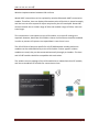
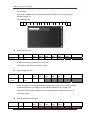
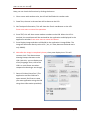
Getting started Connect the LCD to a USB port, windows will automatically detected new hardware “UART TFT LCD”. Select the location of the “driver” folder and continue with window’s instruction. Control software requires Microsoft .NET framework 3.5 or above. .NET framework is already included in Windows Vista and 7. For Windows XP, if you don’t have .NET framework installed, it can be downloaded here: http://www.microsoft.com/download/en/details.aspx?id=17718 Device settings Communcation buad rate: This sets the baud rate for UART communication. The default is 38400bps. (Please make sure your host device supports the specific baud rate) LCD Startup brightness: This sets the LCD brightness when the LCD is powered on, after all the LCD module initialize process, the brightness can be set through UART command. LCD Startup orientation: This sets the orientation for the LCD module (Details see orientation section) Enable LED: Flash the onboard LED during data transfer and display in progress Enable single wire mode: Check to enable single wire mode, uncheck to enable full wire mode (Details please see transmission mode) Enable single wire CKSUM: Enable LCD module to check UART command’s checksum before processing the command. (Details please see transmission mode) Test LCD Text Area: Text to be displayed to LCD Font no: 1 to 10 for default fonts, 11‐15 for custom fonts (Please refer to font section) Clear screen : Clear the LCD screen Display text: Display text to the LCD screen Find color code: This is used to find the 16bit color code (0‐65535) if default color palette is not used Transferring images/icons to the serial flash The serial flash of the LCD module is a 32Mbit(4Mbyte) flash. It consist of 1024 sectors of 4096 bytes. The sector number is used to identify which image is displayed to the LCD during the UART command. Sector number 0 to 256 is used for storing fonts, therefore sector number 257 to 1023 is for user to store their image. Page 5
UART TFT LCD user manual
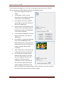
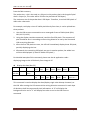
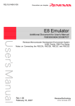
To download the image/icon to the flash, the image should be less than 320x240 pixels in dimension. JPEG, BMP, ICO, PNG are acceptable format. 1. Press Load Image and select the image 2. If the image is valid, it can be previewed in the software. Relevant information can be displayed 3. For example, this icon is a 36x36 pixel image. It size to be written to the flash is 2600 bytes. 4. Enter the sector start address to be written. This is the address used to identify this image to be displayed in the UART command. 5. As this image is 2600bytes, this will take up one sector ( one sector is 4096 bytes) 6. For example, a image with 160x120 pixel will be 38408 bytes which takes up 10 sectors, the sector start address will be used to identify this image for display during UART command. 7. After confirmation, Press Write, the image will be written to the flash. 8. The image will be automatically added to the Image List. Pressing the save image list will save the images list and their sector information to the serial flash, so that next time when you want to import images to the device, you will know how many images and their sector location is, then you can find free consecutive sectors to write further images. Page 6
UART TFT LCD user manual
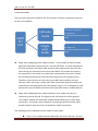
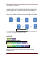
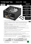
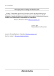
Connection Mode: There are two connection mode for the LCD moduel, and their connection mode can be set in the software. UART TFT LCD
Full wire mode
Single wire mode
LCD Select: Required
Rx: Required
Tx: Required when touchpad is used
Rx: Required
Tx: Required when touchpad is used
Single wire mode(single wire mode uncheck) – In this mode, at least two data signal are required to control the LCD – Rx and LCD select. To write command to the LCD, first assert LCD select LOW, and then write command to the LCD, after finish writing the command, assert LCD select HIGH. LCD module will process the command. In this mode, any UART data received when LCD select is HIGH will not be processed by the LCD and will be bypassed to the bypass out pin. Therefore, other devices can share the same UART data issued by the host. Similarly, when LCD select is LOW, UART data received will be processed by the LCD and won’t be bypassed to the UART bypass out pin. This is designed as most arduino has only one UART interface and to send UART data to multiple devices. Single wire mode(single wire mode checked): In this mode, only Rx pin is required to control the LCD. The signal on the LCD select pin will be ignored. This mode is suitable for USB>UART module without GPIO pins or other flow control pins. This mode is also suitable for connecting external wireless UART module of which only Rx and Tx is available for UART transmission. The following pins are optional and are usable in both mode: Tx pin: This is used to transmit data from the LCD to the host. This pin Page 7
UART TFT LCD user manual
is used to send touchpad coordinates to the host for processing after receiving the Get touchpad command. If touchpad input is not used, this Tx pin can be left unconnected. LCD busy pin: This pin is used to signal the host whether the LCD is busy and is not accepting command. Active LOW. If the host send command to the LCD when it is HIGH, command may not be processed. If this pin is left unconnected, appropriate delay is needed between commands sent by host. Touchpad Interrupt pin: This pin is used to signal the host whether the touchpad is touched or not. Active LOW. If this pin is not connected and host want the touchpad information, host can send request touchpad information periodically to poll touchpad information. LCD reset pin: Reset the LCD. Active LOW. Normally not used. UART Bypass pin: UART bypass output. Used to connect other UART device to receive bypassed UART data. 3.3V/0V logic output Page 8
UART TFT LCD user manual
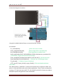
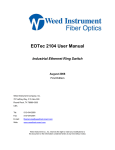
Connection diagram to arduino Using the included arduino library to control the LCD is simple. For example: Clr_screen(BLACK); //Clear the screen in black Draw_image(243,160,160); //draw Image 243 at cord (160,160) Set_LCDbrightness(180); //set brightness to medium level Draw_progressbar(LIGHT_GREY,GREEN,0,0,239,9,(char)percent_completed,15); // Generate a progress bar based on percentage Draw_text(BLACK,YELLOW,”Hello World!”,0,10,239,138,7); // Draw some text Draw_box(CYAN,150,150,230,230,5); // Draw a box, simulating a button TP_pressed(); // Check of screen is touched If (TP_press()) { x=get_XCord(); y=get_YCord(); } //Get touchpad coordinate information The arduino library “UARTLCD” is used to control the LCD in single wire mode. Just place it in libraries folder and run the demo application. There is also an example of creating a TFT LCD clock with UART TFT LCD, DS1307 and DHT11. Please see arduino example or quick start guide for more information. Page 9
UART TFT LCD user manual
Connection diagram to PC’s USB > UART adapter Connection in single wire mode is demonstrated by the green wires. Connection In full wire mode is demonstrated by blue wires. RS‐232 flow control signal (DTR and DSR) are used as GPIO pins to control LCD select and input of LCD Busy. C# libraries and demo application is included for application development. The demo applications also demonstrate sending command and receiving touchpad information from the LCD module. It also demonstrates advance functions of the LCD module, drawing image and character bitmap to LCD directly. The library is tested on common USB>UART adapter including CP2102, FT232 and PL2303HX and will work on other virtual COM port USB>UART device on common baud rates up to 500000bps. Page 10
UART TFT LCD user manual
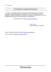
Connection diagram to Raspberry Pi UART TFT LCD can be connected to the onboard UART on Raspberry Pi (\dev\ttyAMA0) on the GPIO headers, or USB to Serial device (\dev\ttyUSB0). Connection in single wire mode is demonstrated by the green wires. Connection In full wire mode optionally is demonstrated by blue wires. GPIO pins to control LCD select and input of LCD Busy. With the LCD module, information of the Raspberry Pi can be displayed and therefore you can leave your main monitor shut off or unconnected, especially useful in server environments. The touchpad can also serve as a simple input system to R‐Pi. A simple python script (Linux) using Pyserial and psutil is included in the download package to demonstrate turning the LCD into a colored system information gadget displaying R‐Pi hardware status, such as CPU usage, network utilization, memory usage etc. Page 11
UART TFT LCD user manual
Wireless Implementation between LCD and host Wired UART transmission can be replaced by wireless Bluetooth UART transmission module. Therefore, host can display information to the LCD which is placed remotely and the host can also respond to inputs acquired by the LCD touchpad. General BT wireless module has an indoor range of 10m and outdoor range of 100m, some are even longer. This transmission is transparent to the LCD module, so no specific settings are required. However, baud rate of 115200 or slower and checksum should be enabled in order to prevent LCD process corrupted data in case there is one. The LCD PCB has a footprint specific for HC‐07/06 Bluetooth module and these modules can be soldered directly to the LCD module. If other type BT wireless modules are used, they can be connected externally through pin headers. The host and LCD BT module should be compatible with each other. The wireless version package of the LCD module has a onboard wireless BT module, and also a standalone BT module for connection to host. Page 12
UART TFT LCD user manual
LCD command and packet format In the full wire mode, LCD will receive and parse UART data once LCD select is LOW. It will store the data received in a 720byte buffer. After the packet is transferred, host will assert LCD select HIGH. After this pin is asserted HIGH, the LCD will assert LCD busy LOW within 10us and scan for a packet in the data buffer. If a valid packet is received the LCD will process the command. After the command or display is finished, the LCD module will assert LCD busy HIGH, indicating LCD is ready to receive another command. Assert LCD_select LOW
Send UART command
Assert LCD_select HIGH
LCD_busy becomes HIGH
LCD ready to accept another command
After completed, LCD_busy becomes LOW
LCD process command and display to LCD
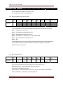
Flow control for fullwire mode In the single wire mode, the signal on the LCD select pin will be ignored and LCD will continuously receive UART data and scan for a packet. Packet Format: Full wire mode – Start byte (Decimal 36)
Command and data bytes
Single wire mode (without checksum) Start byte (Decimal 36)
Command and data bytes
First End byte (Decimal 160)
Second End byte(Decimal 157)
Single wire mode (with checksum) – Start byte (Decimal 36)
Command and data bytes
checksum byte
First End byte (Decimal 160)
Second End byte(Decimal 157)
If the checksum is enabled, the host should send the packet checksum value just before the two end bytes. The LCD module will process the packet only if the checksum is correct. Page 13
UART TFT LCD user manual
Basic Command List Enquire LCD Status Clear Screen Draw Rectangle Draw Box Draw Circle Draw Triangle Draw progress bar
Draw Line
Draw Image from flash
Draw Text
Set LCD brightness
Get Touch pad value (7 bit)
Byte1 Byte2 and 3 Byte4 and 5 15 Byte6 and 7
Byte8 and 9
Byte10 and 11
Byte12 and13
Byte14 and 15 Byte16 and 17 16 17 Color
Color X0 Y0 X1 Y1 18 19 Color
Color X0 X0 Y0
Y0 Color
Background Color
Color
Image Start sector Background Color
Brightness value
X0 Bar Color X0 X0 Y0
X0 Y1
Fill Circle?
Y1
X1 Box Width 20 22 X1
Circle radius
X1
Y0 X2
Y1 Y0
Y0 X1
Y1
Y2 Percenta
ge Line Width Gradient Value
Font Color X0 Y0 X1 Y1 Font Text Start number 23 32 33 48 54 Common Value definitions Color format: Color used is a 16bit double byte RAW format (0‐65535) (RRRRRGGGGGGGBBBBB). Please refer to color palette for color representation. Less commonly used color can be converted to 16 bit value using Image loader software. Coordinates format: (X,Y) X is the horizontal axis from corner (0,0) while Y is the vertical axis from corner (0,0). For the corner representation, see orientation section. For example: Clear the screen in White Full wire: 1. Wait for LCD Busy to be HIGH 2. Assert LCD Select LOW 3. Send byte 36 (Start byte) Page 14
UART TFT LCD user manual
4. Send byte 16 (command Clear Screen) 5. Send byte 255 (Higher byte of 65535, 65535 is the 16bit color value of White) 6. Send byte 255 (Lower byte of 65535, 65535 is the 16bit color value of White) 7. Assert LCD Select HIGH Single Wire 1. Send byte 36 (Start byte) 2. Send byte 16 (command Clear Screen) 3. Send byte 255 (Higher byte of 65535, 65535 is the 16bit color value of White) 4. Send byte 255 (Lower byte of 65535, 65535 is the 16bit color value of White) 5. Send byte 50 ( Only if checksum is enabled) I. Calculation of byte checksum: (Sum of all the bytes in the packet before this checksum byte, If the result is greater than 255, the checksum will be the remainder divided by 256) = remainder of (36+16+255+255)/256 = 50 6. Send byte 160 (First end byte) 7. Send byte 157 (Second end byte) Page 15
UART TFT LCD user manual
Enquire LCD Status Command definitions Enquire LCD status (Decimal 15) Byte1 Byte2 and 3 Byte4 and 5 15 Byte6 and 7
Byte8 and 9
Byte10 and 11
Byte12 and13
Byte14 and Byte16 and 17
15 Byte10 and 11
Byte12 and13
Byte14 and Byte16 and 17
15 Byte10 and 11
Y1 Byte12 and13
Byte14 and Byte16 and 17
15 If LCD is ready and idle, it will return 9 bytes. Byte1 – 120, Byte2 – 79 (ASCII char “O”), Byte3 – 75(ASCII char “K”), Byte4 – 13, Byte5 – 10, (ASCII line break+CR) Byte6 – LCD orientation setting, Byte7‐ One wire mode enabled Byte 8‐ checksum enabled, Byte 9 ‐ 136. ASCII will read “OK”
Clear Screen
Draw Rectangle
Clear Screen (Dec 16) Byte1 Byte2 and 3 Byte4 and 5 16 Color
Byte8 and 9
Clear the whole screen with to the color sent Draw Rectangle (Dec 17) Byte1 Byte2 and 3 Byte4 and 5 17 Color X0 Byte6 and 7
Y0 Byte8 and 9
X1 Draw a solid rectangle, can be simulated as a button for touchpad (X0,Y0) will be the coordinate of the upper left corner of the rectangle (X1,Y1) will be the coordinate of the lower right corner of the rectangle Draw Box (Dec 18) Byte1 Byte2 and 3 Byte4 and 5 Byte6 and 7
Byte6 and 7
Byte8 and 9
Byte10 and 11
Byte12 and13
Byte14 and Byte16 and 17
15 Page 16
UART TFT LCD user manual
Draw Box
Draw Circle
18 Color X0 Y0 X1 Y1 Box Width
Draw a rectangle without fill, can be simulated as a button for touchpad (X0,Y0) will be the coordinate of the upper left corner of the rectangle (X1,Y1) will be the coordinate of the lower right corner of the rectangle Box Width will be the width of the box in pixel Draw Circle (Dec 19) Byte1 Byte2 and 3 Byte4 and 5 19 Color X0 Byte6 and 7
Y0 Byte8 and 9
Circle radius
Byte10 and 11
Fill Circle?
Byte12 and13
Byte14 and Byte16 and 17
15 Draw a Circle, can be simulated as a button for touchpad (X0,Y0) is the coordinate of the center of the circle Radius is radius of circle in pixel. If the Fill Circle byte is 1, Circle will be filled with solid color, otherwise circle will be a outline circle. Draw Triangle (Dec 20) Byte1 Byte2 and 3 Byte4 and 5 Draw Triangle 20 Color
X0 Byte6 and 7
Y0
Byte8 and 9
X1
Byte10 and 11
Y1
Byte12 and13
X2
Byte14 and Byte16 and 17
15 Y2 Draw a outlined triangle according to the three coordinates sent
Draw progress bar
Draw progress bar (Dec 22) Byte1 Byte2 and 3 Byte4 and 5 22 Background Bar Color
Color Byte6 and 7
X0 Byte8 and 9
Y0 Byte10 and 11
X1 Byte12 and13
Y1 Byte14 and Byte16 and 17
15 Percentage Gradient Value
Draw a progress bar. Bar color – the color of the bar Background color – the color of the background of the bar X0,Y0 – upper left corner of the bar X1,Y1 – lower right corner of the bar Percentage – the percentage of the progress as indicated by the bar color Gradient value – Create a gradient effect of the bar color. Values can be ranged from 0 to 60000. Different values will create a different gradient effect Page 17
UART TFT LCD user manual
Draw Line
Draw Image from flash
For example: Back color: 33808 Font Color: 65535 X0:0 Y0:0 X1:239 Y1:30 Percentage: 50 Gradient value: 33 Command packet: 22 132 16 255 255 0
0
0
0 0
239 0
30 0 50 0 33 Draw Line (Dec 23) Byte1 Byte2 and 3 Byte4 and 5 23 Color
X0 Byte6 and 7
Y0
Byte8 and 9
X1
Byte10 and 11
Y1
Byte12 Byte14 and13
and 15 Line Width Byte10 and 11
Byte12 and13
Byte16 and 17
Draw a line starting from (X0,Y0) to (X1,Y1). Line width is the width of the line in pixel. Draw image (Dec 32) Byte1 Byte2 and 3 Byte4 and 5 32 Image Start X0 sector
Byte6 and 7
Y0 Byte8 and 9
Byte14 and Byte16 and 17
15 Draw an image on the LCD according to image start sector,.If the sector is invalid
Set LCD or does not contain an image or is not the start address of the image, the command will be ignored. (X0,Y0) is the coordinate of the upper left corner of the image drawn. Set LCD brightness (Dec 48) Byte1 Byte2 and 3 Byte4 and 5 48 Brightness Byte6 and 7
Byte8 and 9
Byte10 and 11
Byte12 and13
Byte14 and Byte16 and 17
15 Page 18
UART TFT LCD user manual
brightness
Get Touch pad value (7 bit)
Draw Text
value
Set the brightness value of the LCD, 0‐255. 0 is the dimmest, 255 is the brightness Get touchpad value 7bit (Dec 54) Byte1 Byte2 and 3 Byte4 and 5 54 Byte6 and 7
Byte8 and 9
Byte10 and 11
Byte12 and13
Byte14 and Byte16 and 17
15 This command will return 6 bytes within 5ms after the command is processed Byte1 – Firmware version 0.78, Byte2 – Touchpad coordinate (X) (0‐127) Byte3 –Touchpad coordinate (Y) (0‐127) Byte4 – Touched? (0 – untouched, 1 – touch detected) Byte5 – Byte Checksum of Byte2,3 and 4 Byte6 – 88. If Touchpad interrupt is unconnected, host can poll this command periodically to check whether the touchpad is touched, touched coordinates can also be obtained at the same time. Draw Text (Dec 33) Byte1 Byte2 and 3 Byte4 and 5 33 Background Font Color
Color Byte6 and 7
X0 Byte8 and 9
Y0 Byte10 and 11
X1 Byte12 and13
Y1 Byte14 and Byte16 and 17 15 so on..
Font Text Start number This command will draw text according to the information sent Background color – the background colour of the text Font color – the color of the text Font number – the Font number of the text, There are 10 fonts in the default flash, numbered 1 to 10, with increasing font size. Page 19
UART TFT LCD user manual
The first character of the text will start from byte 16. It should be a single byte ASCII or ASCII extended character. The text string should end with a byte 0. The total characters of the text should not be greater than 680. Line break (Byte 10) can be inserted in the text string for a link break The text will be drawn within the rectangular frame from (X0,Y0) to (X1,Y1) For example: Back color: 65524 Font Color: 63488 X0:0 Y0:0 X1:319 Y1:50 Fontno:6 Text = “123456” Command packet: 33 Cmd 255 244 248
Back color 0 0 FontColor 0 0 X0 0
1
Y0 63
0
X1 50
Y1 0
6
49
50
51 52 53 54 0 Fontno.
1 2
3 4 5 6 end
Back color: 65524 Font Color: 65304 X0:0 Y0:0 X1:319 Y1:50 Fontno:6 Text = “123456” + newline + “7890ab” Command packet: 33 255 244 248 16 0 Cmd Back color FontColor 0 X0 0 0 Y0 1 63 0 X1 50
Y1 0
6
49
50
51
52
53
54
10
Fontno. 1 2 3 4 5 6 Linebk. 55 56 57 48 97
7 8 9 0 a 98
0
b end
Page 20
UART TFT LCD user manual
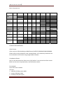
Advanced Command list: These commands can be used to extend the display capabilities of the LCD Module Byte1 Byte2 and 3 Byte4 Byte6 and 5 and 7 Byte10 Byte12 Byte14 and 11 and13 and 15 Byte16 and 17 Y0 Draw Pixel 21 Color Fill Text buffer1
34 Background Font Color Color X0 Y0 X1 Y1 Font number Text Start Fill Text buffer2
35 Background Font Color Color X0 Y0 X1 Y1 Font number Text Start Fill Text buffer3
36 Background Font Color Color X0 Y0 X1 Y1 Font number Text Start Fill Text buffer4
Display Text in buffer
37 Background Font Color Color X0 Y0 X1 Y1 Font number Text Start 38 0 0 Display Display Display Display Buffer 1 Buffer 2 Buffer 3 Buffer 4
Set Writing direction
49 Direction 50 Background X0 Color Y0 X1 Y1 Font Color Display raw data
51 Packet Size (bytes) Pixel data Display dots data
52 Packet Size (bytes) Dots data Get Touch pad value (12 bit)
56 Set Area
X0 Byte8 and 9 Page 21
UART TFT LCD user manual
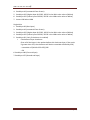
Draw Pixel (Dec 21) Byte1 Byte2 and Byte4 3 and 5 Draw Pixel
X0 Byte1 Byte2 and 3 Byte4 and 5 Fill Text buffer
Byte10 Byte12 Byte14 and 11 and13 and 15 Byte16 and 17 Y0 34,35,36 Background Font or 37 Color Color Byte6 and 7 Byte8 and 9 Byte10 Byte12 Byte14 and 11 and13 and 15 Byte16 and 17 X0 Y0 X1 Text Start
Y1 Font number There are four text buffers which can store the text and its relevant information on the LCD module. They can be filled with command 34,35,36 and 37 for buffer 1,2,3 and 4 respectively. The character of the text to be filled in the buffer should not be greater than 40 characters. This command only store text and their display information in the buffer, but will not display to the LCD. Display text from text buffer (Dec 38) Byte1 Byte2 and 3 Byte4 and 5 Display Text in buffer
Color Byte8 and 9 This command will draw one single pixel at the coordinate (X0,Y0) on the LCD with the color specified To make sure pixels are drawn, use the LCD Set area command to set the area of the display to include the coordinate of the single pixel before issuing this draw pixel command. Fill Text buffer (Dec 34‐37)
21 Byte6 and 7 38 0 0 Byte6 and 7 Byte8 and 9 Byte10 Byte12 Byte14 and 11 and13 and 15 Display Display Display Display Buffer Buffer Buffer 3 Buffer 4
1
2
Byte16 and 17 This command can be used to draw the text in the 4 text buffers. Each text buffers can be drawn individually to the LCD. 0 will not draw the text. 1 will draw the text to the LCD. Set writing direction (Dec 49) Byte1 Byte2 and 3 Byte4 and 5 Set Writing direction
49 Direction value Byte6 and 7 Byte8 and 9 Byte10 Byte12 Byte14 and 11 and13 and 15 Byte16 and 17 Page 22
UART TFT LCD user manual
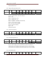
This command is used to set the direction of pixel drawing. The default value for direction is horizontal writing. In horizontal writing, pixel will be drawn in the increment of X, then Y. In the vertical writing, pixel will be drawn in the increment of Y, then X. This command is used to set the pixel direction direction to suite the display data issued by the command “display dot data”
Set LCD Area (Dec 50) Set Area
Byte1 Byte2 and 3 Byte4 and 5 50 Background X0 Color Byte6 and 7 Byte8 and 9 Byte10 Byte12 Byte14 and 11 and13 and 15 Byte16 and 17 Y0 X1 Y1 Font Color This command must be issued to set the area of pixel display before the command “display dot data” or “display raw data”. It set an imaginary rectangular frame within the LCD, and the pixel will be drawn within this imaginary frame. The pixel drawing direction can be set by the command “Set writing direction”. Background and font color information are set and used in conjunction with command “display dot data”. Display raw data (Dec 51) Display raw data
Byte1 Byte2 and 3 Byte4 and 5 51 Byte8 and 9 Byte10 and 11 Byte12 Byte14 and13 and 15 Byte16 and 17 Pixel 2 Pixel 3 Pixel 4 Pixel 5 Pixel 6 Pixel 7 and so on……. Packet Size Pixel data…. (bytes) Pixel 1 Byte6 and 7 This command is used to display 16bit raw color data to the LCD. After setting the LCD area and the writing direction command, each color pixel can be sent to the LCD in this command sequentially and displayed to the LCD. Therefore, the host can directly send image information for the LCD to display instead of drawing the image Page 23
UART TFT LCD user manual
from the flash memory. The packet size – this is the total no. of bytes in this packet, that is the length of pixel data + 4 bytes (ie, This value will be 704 for the pixel data of 700 bytes). The maximum size of the packet data is 700 bytes. Therefore, it can hold 350 pixels of 16bit color value each. For example, to display a icon of 24x24 pixel directly from host, it can be splited into three packets: 1. Use the LCD set area command to set a rectangular frame of 24x24 pixel (X0:0, Y0:0, X1:23,Y1:23) 2. Using the display raw data command, send the first 350 pixels. The sequence of pixel should be sent in according to the writing direction as set by the command LCD set writing direction. 3. After the first 350 pixels are sent, the LCD will immediately display these 350 pixel, partially displaying the icon 4. Afterwards, the remaining 226 pixels are sent in another packet, the whole icon will then be displayed. (a total of 24x24=576 pixels.) For detailed example of this command, please see the c# application code – displaying image to the LCD directly from image in PC Display dot data (Dec 52) Display dots data
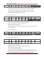
Byte1 Byte2 and 3 Byte4 and 5 52 Byte8 and 9 Byte10 and 11 Byte12 Byte14 and13 and 15 Byte16 and 17 Pixel 65‐80
Pixel 97‐112 and so on…….
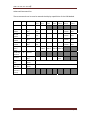
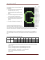
Packet Size dot data (bytes) Pixel 1‐16 Byte6 and 7 Pixel Pixel Pixel 17‐32 33‐48 49‐64 Pixel 81‐96 This command is used to display dot data (display single color bitmap character) to the LCD. After setting the LCD area and the writing direction command. In each byte of dot data, the 8 bits represent 8 pixel information. A “0” will display the background color and a “1” will display font color as set in the LCD Set area command. Page 24
UART TFT LCD user manual
For example to draw a bitmap character “G” of 8x16pixel: 1. Use the LCD set area command to set area (X0:0 Y0:0, X1:7, Y1:15), background color black and font color green. 2. Use the set writing direction command to set horizontal writing direction. 3. Use display dot data command to send 16bytes of dot data as showed in the picture. 4. The LCD will display the character ”G” Using this method, bitmap characters or single color image can be drawn to the LCD in a much faster rate. The drawing direction can also be customize to suite the character render direction. Characters of any language can be displayed to the LCD. The C# application has an example and library to convert text of any languages in Arial Unicode MS or other font type to packets of “dot data” and displayed to the LCD. Get Touch pad value (12 bit) (Dec 56) Byte1 Byte2 and 3 Byte4 and 5 Get Touch pad value (12 bit)
56 Byte6 and 7 Byte8 and 9 Byte10 Byte12 Byte14 and 11 and13 and 15 Byte16 and 17 This command will return 8 bytes within 5ms after the command is processed Byte1 – 78, Byte2,3– Touchpad coordinate (X) (0‐4096) Higher byte first Byte4,5 –Touchpad coordinate (Y) (0‐4096) Higher byte first Byte6 – Touched? (0 – untouched, 1 – touch detected) Byte7 – Byte Checksum of Byte2,3,4,5 and 6 Byte8 – 88. Page 25
UART TFT LCD user manual
If Touchpad interrupt is unconnected, host can poll this command periodically to check whether the touchpad is touched, touched coordinates can also be obtained at the same time. Page 26
UART TFT LCD user manual
FAQ: 1. What is the font included? The font included in the module is Bit Stream Vera Sans. It is a free to use font 2. What is the recommended baud rate setting? The default baud rate is 38400bps and is already fast enough for command and text transfer. If display raw data or display dots data are used, high baud rate can be set to achieve faster data transfer and display speed, baud rate at 500000bps can be achieved using a CP2102 and PL2303HX USB to serial converter module. 3. What is the delay required before another command is sent? The recommend delay time is different for each command and baud speed. As long as LCD busy become HIGH, the LCD can accept the next command. If single wire mode is used, estimation of delay time is required. For command without any display function to the LCD, a delay of 10ms will be sufficient. For command which display to LCD, longer delay will be required. A typical delay for drawing text/image of size about a quarter of the LCD screen will be at least 100ms. Delay time can be tested until the command functions. Delay time should be set longer when using wireless UART modules. 4. Can the “display raw data” and “display dots data” work in single wire mode? Yes. They are tested to function using single wire mode and single wire wireless transmission mode at 700 bytes of data each packet. Nevertheless, if bytes 160 and 157 exist consecutively in the pixel/dots data, it will cause premature packet termination. However, the chance occurrence is very low. Host can implement the filtering of these consecutive bytes in the pixel data if necessary. 5. How often do the polling of touchpad information is needed? It depends on the response time of the touch action required. A typical touchpad data acquire and transmission to host require 10ms. A polling frequency on 2 times per second would be sufficient for button pressed sensing purpose. 6. How many images can I store on the flash? 3Mbyte of space is provided for image storage. It is enough to store 384 60x60pixel images, or 96 120x120pixel images. The size of image files in computer cannot be used for calculation as they are compressed file. 7. Can the LCD display animation? Page 27
UART TFT LCD user manual
Yes. The LCD can load the animation image by image. Frame rate can increase if the resolution is lowered. The frame rate of 10fps can be achieved by repeatedly loading images of resolution 96x96px. ie load one image every 100ms. 8. Can I send command to the LCD module during LCD is busy in order to save transfer time? It is not recommend, although it is feasible as the module use interrupt to store UART data received. However, assertion of LCD select HIGH or sending the end byte should only be performed when LCD busy becomes HIGH, as the LCD will process the command immediately when LCD select is HIGH or end bytes are detected. 9. Should checksum be enabled in the wired single wire mode? It is not necessary. Wired UART transmission has a very high accuracy. 10. What is the usage of the touchpad? The touchpad is a very useful function of the module and it can be served as an buttons or input system to the host. The host can scan the touched coordinates, and trigger downstream activities. 11. Are all the inputs 5V tolerant? Yes. All the inputs are 3.3V and 5V tolerant as there is an on board input buffer. Arduino can be connected directly to the module without any 3.3V logic level conversion. The bypass output and other output pins are 3.3V/0V logic level and is compatible with a 5V arduino system. 12. Why I cannot upload sketch to arduino when arduino’s Rx is connected to UART TFT Module? Arduino IDE software upload sketches to arduino via UART. If arduino’s Rx is connected to UART TFT Module, there will be traffic collision ( Two UART signal is transmitted to arduino’s Rx). Therefore, after disconnecting Rx connection to the module, sketches can be uploaded to arduino normally. Arduino’s Tx to TFT module do not need to be disconnected for successful upload as arduino’s Tx can be connected to multiple inputs. Page 28
UART TFT LCD user manual
LCD Module Orientation The LCD module can be set in different orientation to suite user’s display orientation. It can be set in the Image loader application. The default orientation is 0°. For each orientation, the coordinate maximum X and Y value may be different and shown below: Page 29
UART TFT LCD user manual
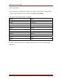
Colour information: The LCD module is a 16bit colour module. The colour of each pixel is represented by a 16bit( 2 byte) information in the format of RRRRRGGGGGGBBBBB. The colour of some basic colour is as follow: 0x0000 Black 0xFFFF White 0xBDF7 Light Gray 0x7BEF Dark Gray 0xF800 Red 0xFFE0 Yellow 0xFBE0 Orange 0x79E0 Brown 0x07E0 Green 0x07FF Cyan 0x001F Blue 0xF81F Pink For other color values, there is a simple conversion tool in the main Image loader application.
Page 30
UART TFT LCD user manual
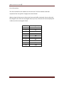
Font Information: The font included in the module has 10 font sizes. The font number and their respective font size (pixel in height) are shown below: When using the Draw text or Draw test from text buffer command, be sure the total font height is less than the rectangular frame (Y1‐Y0). The text will not be displayed if it falls out of the rectangular frame. font no
Font Height in pixel
1 13 2 15 3 19 4 22 5 28 6 34 7 43 8 56 9 74 10 112 Page 31
UART TFT LCD user manual
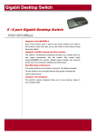
Arduino library examples: A. Demo application (File>Examples>UARTLCD>Demo) 1. Copy the “UARTLCD” folder in the arduino library package to your arduino’s libraries folder. 2. Open arduino main application. 3. Select File>Examples>UARTLCD>Demo 4. Select your arduino board and COM port and upload the sketch. Then, connect the LCD to arduino with four wires. 1. Arduino 5V and GND to LCD’s 5V and GND 2. Arduino Tx (Pin 1) to LCD’s Rx. 3. ARduino Tx (Pin 2) to LCD’s Tx Then, supply your arduino with power (either USB or DC jack), the demo application will run and LCD will display the demo application. Whenever the screen is touched, its coordinate (in 8bit) will be displayed in the LCD. A snap from the arduino demo application: Page 32
UART TFT LCD user manual
B. Fully customizable digital LCD clock with temperature and humidity function. (File>Examples>UARTLCD>arduinoclock) Hardware used: 1. UART TFT LCD module 2. DS1302 Real time clock 3. DHT11 Temp and humidity sensor 4. Arudino (based on UNO) Sketch size: 9826 bytes Connection: DHT data to Pin2, DS1302 I/O, SLK, CS to Pin 6,7,8 Page 33
UART TFT LCD user manual
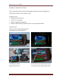
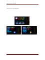
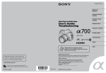
Raspberry Pi Application example: Fully customizable system information gadget showing a variety of Raspberry Pi information based on simple python script Hardware used: 1. Raspberry Pi mainboard 2. UART TFT LCD module 3. Wireless upgrade kit(optional) 4. USB to UART converter (optional, when not using onboard UART) Software used: Python script using Pyserial and psutil Code please see rpi‐uarttftlcd.py Left: Wireless version Right: Wired version Touch detected and coordinates shown in the lower right corder (white word) Page 34
UART TFT LCD user manual
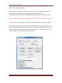
Windows C# demo application. The next step of the guide is to control the LCD using PC running in windows. This application can demonstrate some advanced functions of the LCD. To connect the LCD to PC, you need a USB to serial adapter, or a serial port in a PC. Note: A USB to serial adapter with 5V or 3V TTL level, but not ‐12,+12 RS232 level! Connect 4 wires ‐ Tx Rx Power+ and GND. This demo operate in single wire mode. After connection, launch the UART TFT LCD demo application in the “UART TFT LCD demo” folder. After that, select your COM port, baudrate to 38400, check “one wire mode” and uncheck “enable checksum” and press Open. If everything is OK, it will show LCD OK and all the buttons will be enabled. Page 35
UART TFT LCD user manual
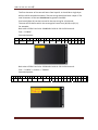
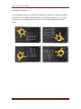
Now, you can check the functions by clicking the button. 1. Clear screen with random color, the LCD will be filled with random color 2. Draw Text, the text in the text box will be drawn to the LCD 3. Get Touchpad information, This will show the Touch coordinates on the LCD. Press once more to cancel the operation 4. Press TEST, this will show some random numbers to the LCD. When the LCD is touched, the coordinates will be retrieved be the application and displayed in the application window. Press once more to cancel this demo. 5. Press Display image and select a 320x240 in the application’s image folder. The image will be drawn directly to the LCD. ( Yes, it is slow, because the baud rate is only 38400). 6. Wait after the image is completely shown, then press display time. This will create a clock. This demonstrate drawing bitmap character to the LCD. (with this, you can display text of any language, fonts, size to the LCD in a much faster rate when compared to drawing a text image). 7. Demo is finished, have Fun! ( The application and the C# driver is open sourced, feel free to create your own application using the LCD using these information provided). Page 36
UART TFT LCD user manual
Snaps from PC demo application: Page 37
UART TFT LCD user manual
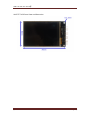
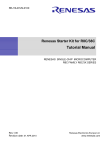
UART TFT LCD Front View and dimension Page 38
UART TFT LCD user manual
Disclaimer: Fonts used in LCD sys info is Bitstream Vera Sans. It is a free‐to‐use font Information in this manual may contain technical inaccuracies or other kind of error, and also subjected to changes. Avoid contact with PCB of any kinds as such may damage the device. Coldtears electronics is not responsible for any consequence or damage arised from using this device. About us: Coldtears electronics specialized in providing TFT LCD modules for embedded systems . We create TFT LCD products which is unique and innovative. We also design applications using TFT LCD for customers to suite their specific needs. For interesting products, please visit our ebay store at and our webpage: http://stores.ebay.com/coldtearselectronicsstore http://www.coldtears.com/electronics/ UART TFT LCD Manual rev.A Copyright © coldtears electronics, 2012 Page 39