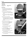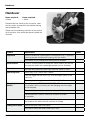
1
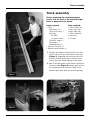
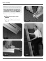
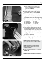
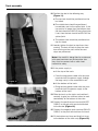
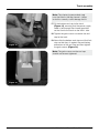
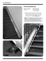
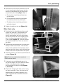
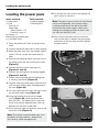
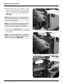
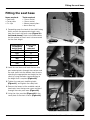
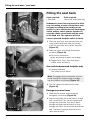
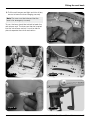
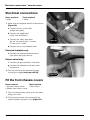
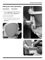
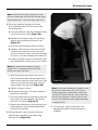
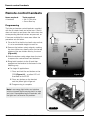
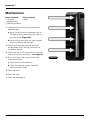
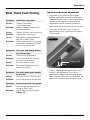
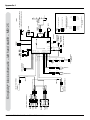
INSTALLATION MANUAL
+
Simplicity
MANISS950
Minivator Simplicity+
installation manual
Smart Seat
Pre-installation check list
1Check that all of the required components
are available. You should have 7 boxes.
These are colour coded so that identification
of any handed components is simple. The
table below shows the colour of the boxes
that you require.
COMPONENT
Left hand
Right hand
Smart Seat base
PURPLE
GREEN
Smart Seat back
Power pack
Fitting kit
Smart Seat Upholstery
BLACK
Bottom Track Section
Top Track Section
e.g. a left hand lift comprises 1 purple and
6 black boxes; a right hand lift comprises
1 green and 6 black boxes.
2 Installation tools required
• Loading toggle
• 2.5mm Allen key
• Shorting links
• 3mm Allen key
• 10mm spanner
• 4mm Allen key
• 10mm socket
• 5mm Allen key
• Narrow nosed pliers • 6mm Allen key
• 13mm socket
(ball ended)
• 17mm socket
• 8mm Allen key
• Side cutters
• Spirit level
• 8mm spanner
• Handlamp
• 13mm spanner
• Hacksaw
• 17mm spanner
• Tin snips
• No. 2 Pozi-drive
Note: The installation engineer must check
with Minivator for the latest installation manual
issue number.
Issue No of this manual is 2011-1
ORIGINAL LANGUAGE ENGLISH
2 MINIVATOR SIMPLICITY+ INSTALLATION MANUAL
Track assembly
Track assembly
Before beginning the installation please
ensure that the track is the required length.
Refer to Appendix 5 for details.
Items required:Tools required:
• Fit kit
• 2.5mm Allen key
Splice bars x 3
• 3mm Allen key
Track ends cap x 1
• 6mm Allen key
Red bag
• 13mm Spanner
8 x bolts
• Hacksaw
4 x grub screws
• Tin snips
Final limit stops x 1
End stops x 1
Mounting feet x 3
• Top track section x 1
• Bottom track section x 1
1Position the bottom section of the track (2m)
on the stairs with the splice holes at the top
(Figure 1). Regardless of the hand of the lift
the rack should always be on the left hand
side of the track when looking up the stairs.
2Bolt in the splice bars to the bottom section of
track extrusion (Figure 2) using 2 grub screws
for the top splice bar and the 4 bolts in the
bottom splice bars (from the red fittings bag).
Figure 1
Figure 2
Figure 3
MINIVATOR SIMPLICITY+ INSTALLATION MANUAL 3
Track assembly
Note: Ensure that the splice bars are positioned
in the track in the correct orientation. The splice
bar has three flat faces and one sloping face.
The sloping face MUST be positioned against
the sloping face on the extrusion (Figure 3).
3If the track is less than 2000mm and cutting
to length on site:
aRemove the charge spring contact
(Figure 4).
bUsing the loading tool, push the plastic
carrier strip up the top section of track
(Figure 5).
Figure 6
Figure 4
Figure 5
4 MINIVATOR SIMPLICITY+ INSTALLATION MANUAL
Figure 7
Track assembly
cAt the top end of the top section use a
hacksaw to remove the excess plastic
carrier strip (Figure 6).
dCarefully replace the charge spring contact.
4Position the top section of track adjacent
to the bottom section of track (Figure 7).
5Offer up the adjacent track section in the
normal way. Run the two core top safety
edge/end cap cable to the top of the track.
Bolt together the two track sections as normal.
Figure 8
6Bolt both sections of track together (Figure 8).
The bolts should be tightened in sequence:
a left bottom
b centre bottom
c right bottom
d left top
e centre top
f right top
Repeat this process until the bolts are all secure
(torque setting 8-9Nm).
7Push the plastic carrier strip down from the
top track section to meet the plastic carrier
strip in the bottom section. The plastic carrier
strip will finish 10mm short of the end of the
track. Carefully feed down the copper charge
strip (Figure 9) and trim to the same length
as the plastic carrier strip.
Figure 9
8Check that the charge strip has made proper
contact with the spring contact at the bottom
of the track (Figure 4).
Note: Ensure that the track is connected
with all faces level so that no step is present
in the joint.
Note: Excessive force can damage and
prevent the spring contact from making
a proper connection.
9Slide the three mounting feet on to the track
(Figure 10).
Note: See page 8 for Slide Track positioning.
Figure 10
MINIVATOR SIMPLICITY+ INSTALLATION MANUAL 5
Track assembly
10Position the feet in the following way
(Figure 11):
aThe top foot should be positioned on the
last tread.
bThe middle foot should be positioned
immediately next to the spliced joint. If the
top section is longer than the bottom then
the foot should be ABOVE the spliced joint,
if not, then the foot should be BELOW the
spliced joint.
cThe bottom foot should be positioned on
the first tread.
11Loosely tighten the feet to stop them from
moving. The feet will help to stop the track
from moving on the stairs while the next
steps are performed.
Note: If the stairlift is being fitted to a staircase
with open bannisters on the bannister side
they must be covered with a solid sheet
material for safety.
12If the power supply is:
a At the top of the track:
Figure 11
•Feed the long power cable with the push
terminals from the power supply through
the large cavity in the assembled track.
bAt the bottom of the track:
•Bring the long power cable with the push
terminals from the power supply to the
bottom of the track.
13Slide the track up the stairs and position it
centrally to give you sufficient room to work
comfortably at the bottom of the stairs.
14Connect the positive push terminal (WHITE
CABLE) to the red push terminal attached
to the busbar (Figure 12).
15Connect the negative push terminal (BLACK
CABLE) to the push terminal from the track.
Figure 12
6 MINIVATOR SIMPLICITY+ INSTALLATION MANUAL
16Fit the bottom end stop and final limit stop
to the bottom of the track only (Figure 13).
Track assembly
Note: The shorter (square ended stop)
must be fitted in the top channel – failure
to do this correctly could damage the lift.
17Fit the bottom end cap to the track
(Figure 14), ensuring that the power supply
cable is fed through the channel provided
so that it exits the track on the WALL side.
18Tighten the grub screws to secure the end
cap to the track.
Figure 13
19Now slide the bottom end stop and final limit
stop so that they sit against the positioning
extensions of the end cap and then tighten
the grub screws (Figure 14).
Note: The grub screws on the end cap
should not be over tightened.
Figure 14
MINIVATOR SIMPLICITY+ INSTALLATION MANUAL 7
Feet positioning
Feet positioning
Items required:Tools required:
• None
• 13mm Spanner
• 13mm Socket
1Slide the track to the side of the stairs that
it will be finally located to position the feet.
The feet should be positioned so that they
are touching the stringer (Figure 15).
Note: If the stringer does not extend to the
tread, i.e. it overhangs the staircase, use a
plumb line to mark a position on the stairs.
The feet should all be positioned in this way.
Third/
last foot
Splice
Figure 15
Second foot
Figure 16
8 MINIVATOR SIMPLICITY+ INSTALLATION MANUAL
Figure 17
Feet positioning
2With the end of the track positioned so that
it is just touching the floor ensure that the
feet are still positioned on the stair treads
as previously described (Figure 11), i.e:
aThe top foot should be positioned on
the last tread.
bThe middle foot should be positioned
immediately above the spliced joint.
cThe bottom foot should be positioned
on the first tread.
3 Tighten the bolts on the feet (Figure 16).
Slide Track only
Figure 18
4Position the first (fixed) foot on the second
step of the staircase. Then position and
loosely fix the second foot to the stairs,
two full steps below the track splice point
(or the end of the track for a single section
track), to allow clearance when the Slide
Track moves (Figure 17). The track should
be approximately 25mm from the nose of
the stairs.
5Position the remaining feet on the steps and
loosely fix them to the stairs. The last foot
needs to be positioned two full steps down
from the top of the stairs, whilst the third foot
should be as close as possible to the splice.
6The feet should sit as close as possible to the
stringer (Figure 18).
Figure 19
Note: Track may need to be moved out
to ensure seat clears.
7If the track was not delivered pre-cut to
the correct length, trim the communications
busbar to the appropriate length to
accommodate the top end cap (Figures
4, 5 and 19).
8Clip on the stringer-side roller covers using
the tacks provided. Then, with the track in
approximately the correct position, put a
screw into each foot to stabilise the track
(Figure 20).
Figure 20
MINIVATOR SIMPLICITY+ INSTALLATION MANUAL 9
Loading the power pack
Loading the power pack
12Fit the top end cap to track and tighten the
grub screws to secure it.
Items required:Tools required:
• Power pack
• Loading toggle
• Fit Kit
• Shorting links
End cap x 1
Green bag
Wood screws x 12
Final limit stops x 1
End stops x 1
Busbar pickup loading tool
(x 2 for Slide Track)
Note: The grub screws on the end cap should
not be over tightened. If the power supply
is being connected at the top of the stairs,
ensure that the power supply cable is fed
through the channel provided so that it exits
the track on the WALL side.
13Now slide the top end stop and final limit
stop so that they sit against the positioning
extensions of the end cap and then tighten
the grub screws.
1Carry the power pack box to the top of the
stairs.
2 Unpack the power pack from its box carefully.
3Move the track away from the stringer slightly,
around 150mm, to give you more room to
work.
4Remove the blanking plates from the side of
the power pack that will be facing the stairs
(Figure 21).
5Connect the limit switch shorting links
(Figures 21 and 22).
6Connect the driving links (or loading toggle)
(Figures 21 and 22).
7Ensure that the busbar pickup loading tool
is correctly positioned (Figure 23).
Figure 21
8Carefully slide the power pack onto the track
until the drive pinion meets the beginning of
the rack (Figure 24).
9Turn the power pack on from the main switch
on the lower safety edge (Figure 25).
10Using the loading driving links or toggle
switch (Figure 26), drive the power pack
onto the track. The power pack should be
driven to a position approximately half way
between the top and middle foot.
11Fit the top end stop and final limit stop to the
top of the track (Figure 27).
Note: The shorter (square ended stop) must
be fitted in the top channel – failure to do
this correctly could damage the lift.
Figure 22
10 MINIVATOR SIMPLICITY+ INSTALLATION MANUAL
Loading the power pack
Figure 23
Figure 26
Figure 24
Figure 27
Figure 25
Figure 28
MINIVATOR SIMPLICITY+ INSTALLATION MANUAL 11
Loading the power pack
Note: The final limit stop jacking screw
should only be used if the final limit is not
being recognised when the pack is run on the
track. Tighten one full turn max after contact
(Figure 28).
Slide Track installations
14When loading the pack take care to correctly
position the two busbar pickup loading tools
(Figure 29).
15In order to load the pack dipswitch 2 on the
main PCB must be set to the OFF position.
Once loaded this dipswitch should be
returned to the ON position to enable the
Slide Track (see wiring diagrams).
Figure 29
Note: Do not drive the power pack in the UP
direction until the top end cap has been fitted.
The busbar may move and lose contact with
the spring at the bottom of the track.
16Connect the power supply to the ring main or
fused spur. A 400mm long “lazy loop” must
be left by the stringer near the point under
the centre of the track where the power cable
enters the track. This is to allow slack for the
Slide Track’s travel (Figure 30).
17Connect the top track safety edge assembly
(active end cap) remembering to attach the
additional wires (Figure 31).
Figure 30
Figure 31
12 MINIVATOR SIMPLICITY+ INSTALLATION MANUAL
Fitting the front chassis
Fitting the front chassis
to the power pack
Items required:Tools required:
• Front chassis
• Side cutters
• 6mm Allen key
• 8mm Allen key
• Spirit level
Two cover plates and various front chassis bolts
and fixings should be packed with the front
chassis assembly including the safety bolt and
four seat back bolts (Figure 32).
Before fitting the front chassis feed the loom
through the tear shaped cover plate and then
attach it to the power pack (Figure 33).
Figure 33
1Depending upon the hand of the stairlift
being fitted, remove the appropriate pair of
knock-outs (Figure 34 – left hand shown).
2Gently pull down the footplate to get access
to the panel.
3Ensure that the loom from the pack is
correctly positioned and does not interfere
with the underpan safety edge (Figure 35).
4Fit the fixing block, bolts and spacers to the
front chassis.
Figure 34
Figure 32
Figure 35
MINIVATOR SIMPLICITY+ INSTALLATION MANUAL 13
Fitting the front chassis
5Offer the seat chassis to the power unit, and
using the bolts and spacers secure the seat
chassis to the power unit, ensuring that the
chassis is in the correct vertical alignment
(Figure 36).
Note: The power unit has an arched slot on
the seat chassis interface, to set the angle
of the seat and footplate.
Note: Use a spirit level positioned on the top
of the front chassis, or on the footplate, to
ensure that correct alignment is achieved.
6Fit the safety bolt (Figure 37). This needs to
be left loose enough to allow the rear cover to
pass behind it.
Figure 36
Note: On left hand installations on staircases
steeper than 38° the alternative safety bolt
position must be used (Figure 38).
Figure 37
Figure 38
14 MINIVATOR SIMPLICITY+ INSTALLATION MANUAL
Fitting the seat base
Fitting the seat base
Items required:Tools required:
• Seat base
• 10mm socket
• Cover plate
• 13mm socket
• 2 x clips
• Narrow nosed pliers
• 6mm Allen key 1Depending upon the hand of the stairlift being
fitted, remove the appropriate knock-outs
from the chassis top rear cover (Figure 39 –
Left hand shown). Refer to the table below
for the number of knock-outs to be removed
for the client height.
Required seat
to footplate
height (mm)
540
515
490
465
440
430
Figure 39
Knock-outs
to be
removed
1
2
3
4
5
5
2Load the seat base and feed the two seat
post retaining bolts through the washers and
the seat stems into the bottom front chassis;
selecting the appropriate seat height for the
client by using the holes corresponding to
the height that is required (Figure 40).
Figure 40
3Tighten the seat post stabilising bolts
(Figure 41), and tighten the safety bolt.
4Remove the lowest of the available central
knockouts from the top rear cover and feed
through the main pack loom (Figure 42).
5Using the clips provided (Figure 43) fit the
cover plate to the front chassis (Figure 44).
Figure 41
MINIVATOR SIMPLICITY+ INSTALLATION MANUAL 15
Fitting the seat base / seat back
Fitting the seat back
Items required:Tools required:
• Seat back
• 6mm ball ended Allen key
edundant connections are present to allow
R
easy re-handing of seats. Connections must
be made according to the handing of the
stairlift; i.e. for a stairlift with left-hand toggle
switch and key switch (always together on
one side), those connections must be made
to left hand arm. The right arm will then
house a powered footplate switch (if fitted).
Figure 42
1Place the seat back onto the seat base and
using a ball ended 6mm Allen key secure
it with the four bolts and washers provided
(Figure 45).
2Make the upper seat wiring connections
as follows (Figure 46);
aKey switch connection:
green and orange to green and orange.
bToggle switch: blue, white and brown
to blue, white and brown
Arm switched powered footplate only
cPowered footplate:
Twin Yellow to twin Yellow
Figure 43
Note: The toggle switch connection must be
made through the interlock loom to enable
the arm interlock functionality (Figure 47).
3Tidy the cables to the back of the seat
(Figure 48).
Emergency swivel lever
1Feed the anti-tamper seal through the
emergency swivel lever (Figure 49).
Figure 44
16 MINIVATOR SIMPLICITY+ INSTALLATION MANUAL
2Near the front flap of the seat there is a large
and a small hole. Pass the anti-tamper seal
through the small hole, then feed it back
through the larger hole and back on itself
through the hole in the end of the anti-tamper
seal. The lever should be attached on the
down side of the lift.
Fitting the seat back
3Pull the anti-tamper seal tight and trim off any
excess to leave the lever hanging securely.
Note: The user must be informed that the
lever is for emergency use only.
To use, the lever should be twisted to break the
anti-tamper seal. The lever can then be inserted
into the swivel lever socket. It must be held in
place to operate the swivel mechanism.
Figure 47
Figure 45
Figure 48
Figure 46
Figure 49
MINIVATOR SIMPLICITY+ INSTALLATION MANUAL 17
Electrical connections / chassis covers
Electrical connections
Items required:Tools required:
• None
• None
1Make seat and footplate electrical connections
(Figure 50).
aConnect the key switch loom
(orange and green).
bConnect the toggle loom
(white, blue and brown).
cConnect the safety edge loom
(flat six way connection: 2 x brown,
2 x red and 2 x violet).
Figure 50
dConnect the six way footplate loom.
Powered footplate only
eConnect the powered footplate looms
(twin yellow and grey comms).
Power swivel only
f Connect the grey powered swivel loom.
gConnect the shielded swivel loom earth
ring terminal.
2Test the function of the powered features,
including the toggle (see pages 24/25).
Fit the front chassis covers
Items required:Tools required:
• Top front chassis cover
• Side cutters
• Bottom front chassis cover
1Clip in the bottom front cover and fit the panel
fixing push studs.
2Fit the top front cover and secure with the
supplied panel fixing push studs (Figure 51).
18 MINIVATOR SIMPLICITY+ INSTALLATION MANUAL
Figure 51
Fitting the seat upholstery
Fitting the seat upholstery
Items required:Tools required:
• Seat upholstery
• Screw driver
1Clip in the seat back, starting with the top
two clips (Figure 52) and then screw in the
seat belt cover mouldings (Figure 53).
2 Fit the main seat cushion.
3 Fit the seat flap cushion.
4Fit the arm upholstery. Starting at the front,
press the upholstery into the arm recess.
(Figure 54).
Figure 52
Figure 53
Figure 54
MINIVATOR SIMPLICITY+ INSTALLATION MANUAL 19
Securing the track
Securing the track
Items required:Tools required:
• Fit kit
• Spirit level
Green bag
• Tape measure
Woodscrews
• No. 2 Pozi-drive
1 Drive the power pack up and down the
stairs to ensure that it will not encounter any
unforeseen obstacles (Figure 55).
Note: Look for any other potential obstacles
such as window ledges or exposed pipework
that could obstruct the movement of the lift
at this stage.
Figure 56
Figure 57
Figure 55
20 MINIVATOR SIMPLICITY+ INSTALLATION MANUAL
Figure 58
Securing the track
Note: If there are any other obstacles move
the track away from the wall until the rear edge
of the power pack can travel freely past them.
2Drive the stairlift to the top of the track.
If the footplate does NOT finish level with
the landing then:
aDrive the stairlift so that the footplate is level
with the top of the stairs (Figure 56).
bMeasure the distance from the top safety
edge to the inside face of the end cap
(Figure 57).
c Drive the stairlift halfway down the stairs.
dCarefully slide the top of the track into the
middle of the staircase so that you have
access to the end stops (you may not need
to do this if you are installing a left hand lift).
eLoosen the grub screws on the bottom stop
(the ramped one) so that you can just slide it.
Note: Be careful not to loosen the grub
screws fully – the bottom stop may slide
all the way down the track.
fSlide the bottom stop down the track so
that the distance from the top edge of the
stop to the inside face of the end cap is the
same as the distance measured from the
safety edge to the end cap (Figure 58).
gTighten the grub screws.
hRe-position the track in its final location as
previously described.
iDrive the stairlift back to the top of the stairs
and check that the footplate now finishes
level with the landing (Figure 57).
jMake minor adjustments as necessary and
repeat process until the footplate finishes
level with the landing.
3Secure the feet to the staircase using the
woodscrews provided in the Green bag
from the fit kit (Figure 59).
Figure 59
Note: If you are installing the Simplicity track
on onto a carpet that is very thick and is
liable to compress significantly under load
you MUST space the track 10mm from the
nose of the staircase. Failure to do so may
result in the footplate safety edge operating,
stopping the lift.
4Fit the power supply to the wall in an
appropriate position using the bracket
supplied.
MINIVATOR SIMPLICITY+ INSTALLATION MANUAL 21
Remote control handsets
Remote control handsets
Items required:Tools required:
• Handsets
• No. 2 Pozi-drive
• 5mm Allen key
Programming
The infra-red remote control handsets supplied
with the lift should work out of the box. If the lift
does not travel up and down the stairs when the
corresponding handset buttons are pressed, or
if there are multiple lifts in one area, follow the
procedure set out below.
1Drive the lift to the third or fourth step so that
it is at a comfortable height to work on.
2Remove the bottom safety edge by undoing
the two visible cross head screws on the top
edge and the one hidden Allen by the track
(Figure 60).
3Slide the bottom safety edge down the track
to expose the control board and batteries.
4Bring both handsets to the lift and then
programme the handset to the board in the
following way.
a For single lift applications:
i Press and hold the red button on the
PCB (Figure 61) – a yellow LED will
illuminate on the PCB.
Figure 60
ii Press any button on the handset
and the yellow light will go out.
iii Programming is complete.
Note: Low energy light bulbs can interfere
with the infrared signal causing the lift to stop
and start. Reprogramming the handsets with
the lights on can resolve this problem.
Figure 61
22 MINIVATOR SIMPLICITY+ INSTALLATION MANUAL
Remote control handsets
bFor multiple lift applications:
i Remove the red dipswitch protection cap
with a small screwdriver (Figure 62).
ii Set the dipswitches on the PCB on both
handsets to the same settings – note
that the next pair of handsets will require
the dipswitches to be set to a different
combination (see Figure 63).
iii Press and hold the red button on the
PCB (Figure 61) – a yellow LED will
illuminate on the PCB.
iv Press any button on one handset and
the yellow light will go out.
Figure 63
v Programming is complete.
5Test that the handsets have programmed
correctly by pressing the up and down button
on each and check that the lift moves in the
corresponding direction.
Fitting the handset holder
Note: The handset MUST be fixed into the
holder by screwing through the holder into
the handset (Figure 64).
1Fit the hand control holder to the wall in the
required position using the fixings supplied
(Figures 65 and 66).
Figure 62
Figure 64
Figure 65
Figure 66
MINIVATOR SIMPLICITY+ INSTALLATION MANUAL 23
Testing
Testing
Items required:
• Handsets
Items required:
• None
All variants
1Sit on the lift and drive up and down the
track to ensure that the footplate clears
the nose of the risers along the complete
length of the track.
2 Check that the lift charges correctly:
aDrive the lift to the top charge contacts
and ensure that ‘-’ shows in the diagnostic
display.
bDrive the lift to the bottom charge contacts
and ensure that ‘-’ shows in the diagnostic
display.
3 Check the key switch operation
aTurn the key to the off position and ensure
that the lift will not drive – ‘0’ should show
in the diagnostic display when you try and
drive the lift with the key switch in the off
position.
Figure 67
bTurn the key switch back on.
4Ensure that all of the safety edges on the
power pack are functioning (Figure 67).
a Drive the lift in the up direction.
bPress the top safety edge
– the lift should stop.
c Drive the lift in the down direction.
dPress the bottom safety edge
– the lift should stop.
5Check the safety edges on the footplate
and front chassis (Figure 68).
a Drive the lift in the up direction.
bPress the upstairs edge of the footplate
– the lift should stop.
c Drive the lift in the down direction.
dPress the downstairs edge of the footplate
– the lift should stop.
24 MINIVATOR SIMPLICITY+ INSTALLATION MANUAL
Figure 68
Testing
e Drive the unit in the down direction.
fPress the underside of the footplate
– the lift should stop.
dDepress the down button and keep it
depressed.
gDrive the lift in the down direction.
eObserve the function of the lift.
The lift should:
hPress the underside of the front chassis
– the lift should stop.
iBeep whilst swivelling the seat to the
drive position.
Power footplate only
1 For arm operated versions:
a Operate the switch under the arm.
ii Drive down the stairs.
2 Sit on the stairlift:
a Drive the lift down from the top of the stairs.
bThe footplate should lift.
bPush the toggle switch in the up direction
and hold it in that position.
cOperate the switch in the opposite
direction.
cObserve the function of the lift.
The lift should:
dThe footplate should lower.
i Drive up the stairs.
2 For seat operated versions:
ii Stop at the top of the track.
a Lift the front seat squab.
iiiBeep whilst swivelling the seat to the
exit position.
bThe footplate should lift.
c Lower the front seat squab.
dThe footplate should lower.
Manual swivel only
1 Check the swivel interlock:
a Drive the lift in the up direction.
bSwivel the seat – the lift should stop.
c Drive the lift in the down direction.
dSwivel the seat – the lift should stop.
Power swivel only
dUse the manual over-ride lever to swivel
back to the drive position.
eUse the manual over-ride lever to swivel
back to the exit position.
fPush the toggle switch in the down
direction and hold it in that position.
gObserve the function of the lift.
The lift should:
iBeep whilst swivelling the seat to the
drive position.
ii Drive down the stairs.
1 Using the handset:
a Drive the lift down from the top of the stairs.
bDepress the up button and keep it
depressed.
cObserve the function of the lift.
The lift should:
i Drive up the stairs.
ii Stop at the top of the track.
iiiBeep whilst swivelling the seat to the exit
position.
MINIVATOR SIMPLICITY+ INSTALLATION MANUAL 25
Testing
Slide Track installations only
2 Sit on the stairlift:
1 Using the handset:
a Drive the lift to the top of the stairs.
a Drive the lift to the top of the stairs.
bPush the toggle switch in the down
direction and hold it in that position.
bDepress the down button and keep
it depressed.
cObserve the function of the lift.
The lift should:
i Drive down the stairs at half speed
moving with the Slide Track.
ii Depending upon the length of the track:
•If the lift does not reach the end of the
track before the Slide Track has completed
its travel then the Slide Track will stop whilst
the lift will continue to the end of the track
and ramp up to normal speed.
•If the lift does reach the end of the track
before the Slide Track has completed its
travel then the stairlift will stop and the
Slide Track lift will continue to the end
of its travel.
cObserve the function of the lift.
The lift should:
i Drive down the stairs.
ii Depending upon the length of the track:
•If the lift does not reach the end of the
track before the Slide Track has completed
its travel then the Slide Track will stop whilst
the lift will continue to the end of the track
and ramp up to normal speed.
•If the lift does reach the end of the track
before the Slide Track has completed
its travel then the stairlift will stop and
the Slide Track will continue to the end
of its travel.
dPush the toggle switch in the up direction
and hold it in that position.
dDepress the up button and keep
it depressed.
eObserve the function of the lift.
The lift should:
eObserve the function of the lift.
The lift should:
i Drive up the stairs.
i Drive up the stairs.
•If the lift does not reach the end of the
track before the Slide Track has completed
its travel then the Slide Track will stop whilst
the lift will continue to the end of the track
and ramp up to normal speed.
ii Depending upon the length of the track:
•If the lift does not reach the end of the
track before the Slide Track has completed
its travel then the Slide Track will stop
whilst the lift will continue to the end of
the track and ramp up to normal speed.
•If the lift does reach the end of the track
before the Slide Track has completed its
travel then the stairlift will stop and the
Slide Track will continue to the end of
its travel.
ii Depending upon the length of the track:
•If the lift does reach the end of the track
before the Slide Track has completed
its travel then the stairlift will stop and
the Slide Track will continue to the end
of its travel.
3Turn off the power supply to the charge
contacts.
4 Repeat steps 1 and 2 above.
5 Turn the power supply back on.
26 MINIVATOR SIMPLICITY+ INSTALLATION MANUAL
Handover
Handover
Items required:
• None
Items required:
• None
Demonstrate the stairlift to the customer, carer
and any users or potential users before leaving
the installation site.
Please use the following checklist to ensure that
all of the items that should be demonstrated are
covered:
Feature
Explanation
Keyswitch
Used to disable the stairlift against unauthorised use – especially
useful to prevent children from playing with the stairlift.
The stairlift will still charge with the keyswitch disabled.
On/off switch
DO NOT turn the stairlift off using this switch unless you will not
be using the stairlift for a prolonged period such as a holiday.
Seat-belt
The seat-belt should be used every time the stairlift is used.
Operating lever
Which way is up / which way is down.
How the toggle can be used, e.g. with the fingers, palm of the
hand, etc.
The delay in pressing the lever before the stairlift will move.
Operating the
stairlift
Always keep your FEET ON THE FOOTPLATE whilst the stairlift
is in motion, and try to avoid your feet hanging over the edges
of the footplate.
Always sit fully back in the chair when the stairlift is in motion.
Demonstrate the ‘normal’ noise that a stairlift will make
in operation.
Remote control
How to call and send the stairlift. The Simplicity can be parked
anywhere on the stairs and will continue to charge.
Folding the stairlift
How to fold and unfold the stairlift.
The stairlift should be folded when not in use.
28 MINIVATOR SIMPLICITY+ INSTALLATION MANUAL
Done?
Handover
Feature
Explanation
Done?
Operating
the swivel
How to operate the swivel.
Never swivel the seat whilst the stairlift is in motion.
Never remove the seat belt until the chair is swivelled.
Never dismount the chair unless the seat is in a locked position.
Never dismount the chair whilst the stairlift is in motion.
Diagnostic codes
Show the section in the user manual about self help, using the
fault codes and the location of the display on the lift.
Reporting a fault
What number should the customer call and what information
do they need to have available when they call.
Emergency hand
winding
When should this be done (overrun, with keyswitch off and
power on).
How to report a stairlift that has overrun repeatedly.
Trapped articles
Reverse the stairlift away from the trapped article and remove
the item before use.
Other warnings
Never allow more than one person to use the stairlift at any one
time. The maximum carrying capacity is 140kg (22 stone/308lb).
The stairlift is designed for carrying people only.
NEVER allow children to play on or with the stairlift.
NEVER allow water to come into contact with the components in
the stairlift. If you have to transport liquids DO SO WITH CARE.
NEVER place objects in or on the track, or leave objects on the
stairs, where they could come into contact with the stairlift in
operation. Your stairlift is fitted with sensitive side edges and
undertray on the footplate, which will automatically stop the
stairlift if it detects any obstructions.
NEVER use the stairlift in a standing position.
Maintenance and repairs should only be undertaken by a
qualified engineer to maintain the validity of the warranty.
Under no circumstances attempt to repair or re-site the stairlift
yourself.
Servicing
Recommend that the stairlift is serviced by a qualified engineer
after 12 months and every 12 months after that.
Cleaning
Turn the lift off using the key switch and clean with a damp, not
wet, lint free cloth and a small quantity of washing up liquid.
Do not use abrasive cleaners, bleach or solvent based cleaners
as they can damage the stairlift.
MINIVATOR SIMPLICITY+ INSTALLATION MANUAL 29
Appendix 1
Maintenance
Items required:Tools required:
• Lubricant – • None
petroleum jelly
• Cleaning materials
1Lubricate the rack with a small quantity of
petroleum jelly:
aApply a small amount of petroleum jelly at
4 equally spaced points along the track in
the rack recess (Figure 69).
bRun the lift up and down the track several
times to distribute the lubricant.
2Check all of the safety features on the lift
as described in the ‘Testing’ section of the
installation manual.
3Check that the lift still stops flush with the top
step and adjust as necessary – see page 20.
4Sit on the lift and ride it up and down the
stairs several times:
a Listen for any unusual noises.
bCheck for poor ride quality, especially
across the spliced joint.
5 Clean the track.
6 Clean the seat.
7 Clean the power pack.
30 MINIVATOR SIMPLICITY+ INSTALLATION MANUAL
Figure 69
Appendix 2
Slide Track fault finding
Symptom: Intermittent operation
Cause:Copper strip not flat
– brush ‘bouncing’.
Solution:Flatten or replace copper strip
on comms busbar.
Cause:
Comms line dirty/non-conductive.
Solution: Clean/polish comms strip.
Cause: Bad earth connection between
MS125 & 126EL PCBs.
Solution: Check power pack earth copper
connection is good for full travel
of lift (visual down track).
Symptom:Lift stops and display blanks.
Lift will not drive.
Cause: Thermal fuse overheated.
Solution: Turn the lift off for 30 seconds
and then turn it back on.
Cause: Short on comms circuit.
Solution: Find short between track and
comms and rectify.
Symptom:Lift shuts down when loaded
on to track.
Cause:
Short on comms brush to track.
Solution: Use insulated brush loading tool.
Top limit reed switch adjustment
•The power swivel needs to get a signal
from the reed switch inside the rail to work.
Therefore the reed switch may need moving
upward to the magnet housed inside the
hollow rolled section (captive by M6 hex
head screw facing downward on the fix foot).
•The centre of the reed switch should be
approximately 20mm away from the centre
of the magnet.
Figure 70
Dogging hole
20mm
•There is a dogging hole that the reed switch
locates in for a reference. This can be
overridden by depressing the inside of this
hole to depress the catch, and then slide the
reed switch up the channel to get a signal.
Symptom:Power swivel will not operate.
Cause: Incorrect top limit reed switch
set up on Slide Track.
Solution: Adjust the limit switch position
(Figure 71).
MINIVATOR SIMPLICITY+ INSTALLATION MANUAL 31
Appendix 3
Diagnostic codes
Code:Meaning:
None
No display.
Description:
Telephone fault finding action:
Ask client to press toggle and see if display comes
on. Ask if main power switch on the lift is turned on.
If does not correct fault – send engineer.
On site fault finding action:
Check batteries. Check display board is working
correctly. Check comms circuit for short circuit.
Code:Meaning:
Okay
Charging.
Code:Meaning:
0
Final limit activated.
Description:
Description:
Keyswitch, seat swivel, OSG or overrun activated.
Telephone fault finding action:
If no other code is displayed and lift does not drive
– are the arms fully down? Ask client if 8 or 9 show in
the display when the toggle switch is activated – if no
send an engineer.
0
Telephone fault finding action:
Ask client to ensure keyswitch is on and seat is fully
swivelled to drive position. If this does not correct
the fault – send engineer.
On site fault finding action:
Send engineer to check toggle and arm circuit.
On site fault finding action:
Test each item in turn to determine fault.
Code:Meaning:
1
Requires charge.
Code:Meaning:
2
Off charge.
Description:
Description:
Telephone fault finding action:
Ask client to drive lift to charge contacts – if ‘Okay’
code does not show send engineer.
Telephone fault finding action:
Ask client to drive lift to charge contacts – if ‘Okay’
code does not show send engineer.
On site fault finding action:
Drive lift to charge contacts. Check charging circuit if
‘Okay’ code not displayed.
On site fault finding action:
Drive lift to charge contacts. Check charging circuit
if ‘Okay’ code not displayed.
Code:Meaning:
3Top stop – Right hand
Bottom stop – Left hand.
Code:Meaning:
4Top pressure – Right hand
Bottom pressure – Left hand.
Description:
End limits activated.
Description:
Safety edge (up/down direction) activated – footplate.
Telephone fault finding action:
Ask client to tap trunnion guards in case they are stuck.
If this does not correct the fault – send engineer.
Telephone fault finding action:
Ask client to tap footplate edges. If this does not
correct the fault – send engineer.
On site fault finding action:
Check end limit circuit and trunnion guards.
On site fault finding action:
Check footplate leading edge.
1
3
32 MINIVATOR SIMPLICITY+ INSTALLATION MANUAL
2
4
Appendix 3
Code:Meaning:
5Bottom stop – Right hand.
Top stop – Left hand.
Code:Meaning:
6Bottom pressure – Right hand.
Top pressure – Left hand.
Description:
End limits activated.
Description:
Safety edge (down/up direction) activated
– footplate, underpan.
5
Telephone fault finding action:
Ask client to tap trunnion guards in case they are stuck.
If this does not correct the fault – send engineer.
On site fault finding action:
Check end limit circuit and trunnion guards.
Code:Meaning:
7
Low voltage.
7
Description:
Batteries approaching critical level.
Telephone fault finding action:
Ask client to drive lift to charge contacts – if ‘Okay’
code does not show send engineer. If the lift will not
drive – send engineer.
6
Telephone fault finding action:
Ask client to tap footplate edges. If this does not
correct the fault – send engineer.
On site fault finding action:
Check footplate bottom and downside and chassis
underpan.
Code:Meaning:
8Up direction – Right hand
Down direction – Left hand.
8
Description:
Shows when toggle switch is activated in up/down
direction.
Telephone fault finding action:
None.
On site fault finding action:
Drive lift to charge contacts. Check charging circuit if
‘Okay’ code not displayed. If lift will not drive replace
batteries and check charging circuit.
On site fault finding action:
None.
Code:Meaning:
9Up direction – Left hand.
Down direction – Right hand.
Code:Meaning:
A
Hinge open.
Description:
Shows when toggle switch is activated in down/up
direction.
Telephone fault finding action:
None.
A
Description:
Telephone fault finding action:
None.
On site fault finding action:
None.
On site fault finding action:
None.
Code:Meaning:
b
Switch active.
Code:Meaning:
C
IR Address fail.
Description:
A switch is active at power on i.e. Toggle up,
Toggle down, IR up IR down or Learn.
Description:
The IR Address (Dip switch) does not match.
Telephone fault finding action:
Send engineer.
On site fault finding action:
A short circuit has occurred on toggle circuit
– check circuit.
C
Telephone fault finding action:
Send engineer.
On site fault finding action:
Re-program handsets.
MINIVATOR SIMPLICITY+ INSTALLATION MANUAL 33
Appendix 3
Code:Meaning:
dRelay not open (stopped).
Code:Meaning:
ERelay not closed.
Description:
The main power relay is welded closed.
Description:
The main power relay did not close.
Telephone fault finding action:
Send engineer.
Telephone fault finding action:
Send engineer.
On site fault finding action:
Replace main board.
On site fault finding action:
Check battery voltage and replace if necessary,
otherwise replace main board.
Code:Meaning:
F
Brake semi-conductor failed.
Code:Meaning:
g
Brake not connected.
Description:
Description:
Telephone fault finding action:
Send engineer.
Telephone fault finding action:
Send engineer.
On site fault finding action:
Replace main board.
On site fault finding action:
Check brake.
Code:Meaning:
HRelay not open (Pre delay).
Code:Meaning:
JHinge interlock switch error.
Description:
The main power relay is closed early.
Description:
F
H
Telephone fault finding action:
Send engineer.
On site fault finding action:
Replace main board.
E
L
Telephone fault finding action:
Send engineer.
On site fault finding action:
Replace hinge interlock roller switch.
Code:Meaning:
L
Current limit exceeded.
Code:Meaning:
n
Half speed.
Description:
Description:
Telephone fault finding action:
Check client understands loading limits.
Send engineer if persistent fault.
Telephone fault finding action:
Send engineer if permanently showing.
L
On site fault finding action:
Check motor and track for obstructions.
34 MINIVATOR SIMPLICITY+ INSTALLATION MANUAL
On site fault finding action:
Check reed switches and dipswitch settings.
Check battery voltage.
Appendix 3
Code:Meaning:
o
Default Eeprom.
Code:Meaning:
P
PS no reply.
Description:
The Eeprom has been reset to its default value
(Flash Failure).
Description:
Powered swivel did not respond.
Telephone fault finding action:
Send engineer.
On site fault finding action:
Replace main board.
Code:Meaning:
r
No charge current.
Description:
Activated.
Telephone fault finding action:
Check that power supply is switched on from mains
supply. If yes send engineer.
P
Telephone fault finding action:
NOT YET ACTIVE.
On site fault finding action:
NOT YET ACTIVE.
Code:Meaning:
UNo float indication V1.19
software and later only.
U
Description:
Faulty power supply.
Telephone fault finding action:
Send engineer.
On site fault finding action:
Check power supply.
On site fault finding action:
Replace power supply.
Code:Meaning:
ySoftware error.
Code:Meaning:
N/AOver current.
Description:
The main control board has a software fault.
Description:
N/A.
Telephone fault finding action:
Send engineer.
Telephone fault finding action:
Send engineer with a service exchange power pack.
On site fault finding action:
Replace main board.
On site fault finding action:
Replace power pack.
Code:Meaning:
N/ALift is in “sleep mode” to
conserve battery power.
.8.
Description:
Telephone fault finding action:
None.
On site fault finding action:
Press toggle or handset button to wake lift.
Note: If the display is showing
anything but the diagnostic codes
listed it requires resetting.
Drive the lift off the charge contacts.
Turn the main switch on the unit off
for 10 seconds and then back on.
MINIVATOR SIMPLICITY+ INSTALLATION MANUAL 35
1
2
1
2
1
2
UNDERPAN
SW6
FOOTREST
TOP EDGE
SW7
SW5
FOOTPLATE
SW4
SW3
SW2
FOOTREST
BOTT EDGE
TOP
EDGE
UNDERPAN
BOTT
EDGE
1
2
1
2
1
2
RED
BROWN
RED
VIOLET
GREY
BROWN
BROWN
VIOLET
VIOLET
ORANGE
ORANGE
6
5
4
3
2
1
1
2
3
4
5
6
SW8
VIOLET
BROWN
GREY
VIOLET LOOP
1
2
SEE R/H
CIRCUIT
VIOLET
2
1
CABLE
SPLICE
BROWN
CHASSIS BOTTOM SAFETY EDGE
VIOLET
VIOLET
6 LOOP
5
4
3
2
1
1
2
3
4
5
6
VIOLET
SW9
FRONT CHASSIS SAFETY EDGES
RED
TAG
RED
TAG
1
2
3
BROWN
BROWN
CABLE
SPLICE
VIOLET
SW10
BLUE
TAG
BLUE
TAG
BLUE
TOP-END LIMIT
SEAT TO POWERPACK
CONNECTOR
M
F
SW11
OSG
YELL TAG
M
F
YELL TAG
WHITE
WHITE
BLUE
TOP-END LIMIT
FINAL LIMIT
5
BLACK
CON-3
CON-3
CON-3
CON-3
CON-3
CON-3
CON-3
CON-2
CON-2
CON-2
CON-1
CON-1
CON-1
IR SENSOR 2
1A
BLACK
HINGE FUSED
E-STOP DETECT
9
8
7
6
4
BLACK
3
2
1
BOTT-END LIMIT
VIOLET
CHASSIS BOTT SAFE-EDGE
8
7
BOTT-END LIMIT
GREY
SW12
5
4
YEL/BLK STRIPE 6
SAFE-EDGE COMMON
E-STOP & KEY DETECT
CHASSIS TOP SAFE-EDGE
ORANGE
BROWN
2
BLUE
UP DIRECTION
3
1
GREEN
TOGGLE COMMON
SHIELDED CABLE
1
2
3
DOWN DIRECTION
F
M
TRACK
OVERRUN
SEAT TO POWERPACK
CONNECTOR
BLACK
IR SENSOR 1
DIAG
5A
1
BULLET
F
RING TERMINAL
CONNECTOR
+
M1
MOTOR
MOTOR
BLACK
BLACK
RED
WHITE
BLACK
-
-
-
-
+
+
+
-
+
FOOTPLATE
M2
BATT
BATT
BATT
BATT
BATT
BATT
BATT
BK
BK
POWER SWIVEL
CONNECTION
HINGE/PLATFORM
COMMS DATA
CONTACT
1
2
3
3 WAY
CONN
RED
(POWERED OPTIONS ONLY)
HINGE DATA
BROWN
2
1
1
2
BOTTOM LIMIT
SEE R/H
CIRCUIT
VIOLET
VIOLET
GREY
2
1
BLUE
2
1
1
2
TOP LIMIT
1
1
1
1
1
1
WHITE
1
2
WHITE
1
2
3
8 WAY CONNECTOR
9 WAY CONNECTOR
AV OUTPUT SWITCHED 0V
BLK/WHT STRIPE
IR 1
2
IR 2
1
24VDC
AV OUTPUT +
RED
4
3
2
1
AUTO FOOTPLATE
YELLOW
CHRG
DIAGNOSTIC
DISPLAY
BK1
1
2
1
M F
KEY
1
1
2
MULTI-PIN CONNECTOR
PUSH-ON CONNECTOR
MOTOR
SW13
BATTERY
ISOLATION
20A
1
ON
4
3
DIP 2
2
FUNCTION OF DIP SWITCHES
ON SMT PCB
ON
1
4
DIP 1
2
3
ALL SAFETY CIRCUITS SHOULD
BE NORMALLY CLOSED
M-
M+
BATTERY
PACK
DISCONNECT
BRAKE
CHARGE NEGATIVE THROUGH CHASSIS
33V CHARGE POSITIVE INPUT VOLTAGE
CHARGE
PING ENABLE
SW1
DEFAULT OFF
BROWN
PLATFORM ENABLE
PLATFORM DISABLE
CHASSIS TOP SAFETY EDGE
DEFAULT OFF
PING DISABLE
2
1
1
2
3
4
5
6
1
2
3
4
5
6
SLIDE ENABLE
SLIDE DISABLE
UNUSED
FAST RAMP
SPADE
UNUSED
BULLET
SLOW RAMP
36 MINIVATOR SIMPLICITY+ INSTALLATION MANUAL
SPADE
DEFAULT OFF
BK2
Simplicity+ block schematic – left hand stairlift – MS125
Appendix 4
UNDERPAN
SW7
SW6
FOOTREST
BOTT EDGE
1
2
1
2
SW5
SW4
SW3
1
2
FOOTREST
TOP EDGE
BOTT
EDGE
UNDERPAN
SW2
1
2
1
2
1
2
RED
BROWN
RED
VIOLET
GREY
BROWN
BROWN
VIOLET
VIOLET
ORANGE
ORANGE
VIOLET
BROWN
VIOLET
SW8
BROWN LOOP
6
5
4
3
2
1
BROWN
LOOP
1
2
3
4
5
6
1
2
SEE L/H
CIRCUIT
2
1
CABLE
SPLICE
VIOLET
GREY
BROWN
CHASSIS BOTTOM SAFETY EDGE
6
5
4
3
2
1
1
2
3
4
5
6
BROWN
CABLE
SPLICE
BROWN
VIOLET
SW9
TOP
EDGE
SEE L/H
CIRCUIT
RED
TAG
RED
TAG
1
2
3
VIOLET
BLUE
TAG
BLUE
TAG
3
SW12
BLUE
BLUE
TOP-END LIMIT
TOP-END LIMIT
SEAT TO POWERPACK
CONNECTOR
M
F
SW11
OSG
YELL TAG
M
F
YELL TAG
WHITE
WHITE
BLACK
BOTT-END LIMIT
FINAL LIMIT
BLACK
BOTT-END LIMIT
VIOLET
CHASSIS BOTT SAFE-EDGE
6
CON-3
CON-3
CON-3
CON-3
CON-3
CON-3
CON-3
CON-2
CON-2
CON-2
CON-1
CON-1
CON-1
IR SENSOR 2
1A
BLACK
HINGE FUSED
E-STOP DETECT
9
8
7
6
5
4
3
2
1
8
7
5
BROWN
GREY
YEL/BLK STRIPE
SAFE-EDGE COMMON
E-STOP & KEY DETECT
CHASSIS TOP SAFE-EDGE
2
ORANGE
4
1
GREEN
BLUE
UP DIRECTION
SHIELDED CABLE
TOGGLE COMMON
IR SENSOR 1
1
2
3
DOWN DIRECTION
F
M
TRACK
OVERRUN
SEAT TO POWERPACK
CONNECTOR
SW10
BROWN
IR 1
FRONT CHASSIS SAFETY EDGES
2
1
BLACK
1
2
BROWN
VIOLET
2
1
1
2
BOTTOM LIMIT
SW1
BLUE
2
1
1
2
TOP LIMIT
SWITCHED 0V
BLK/WHT STRIPE
1
1
1
1
1
2
3
8 WAY CONNECTOR
9 WAY CONNECTOR
AV OUTPUT -
2
IR 2
1
24VDC
AV OUTPUT +
RED
4
3
2
1
HINGE DATA
5A
DIAG
1
3 WAY
CONN
MOTOR
MOTOR
BLACK
BLACK
RED
WHITE
BLACK
-
-
-
-
+
+
+
-
+
FOOTPLATE
M2
M1
BATT
BATT
BATT
BATT
BATT
BATT
BATT
BK
BK
POWER SWIVEL
CONNECTION
HINGE/PLATFORM
COMMS DATA
CONTACT
1
2
3
RED
+
CHRG
(POWERED OPTIONS ONLY)
BULLET
F
RING TERMINAL
CONNECTOR
GREY
AUTO FOOTPLATE
YELLOW
BROWN
WHITE
1
1
1 WHITE
2
1
M F
KEY
1
1
2
MULTI-PIN CONNECTOR
PUSH-ON CONNECTOR
MOTOR
20A
1
ON
1
4
3
DIP 1
2
ON
4
3
DIP 2
2
ALL SAFETY CIRCUITS SHOULD
BE NORMALLY CLOSED
M-
M+
BATTERY
ISOLATION
SW13
CHARGE NEGATIVE THROUGH CHASSIS
BATTERY
PACK
DISCONNECT
BK1
2
1
CHARGE
33V CHARGE POSITIVE INPUT VOLTAGE
BRAKE
1
2
3
4
5
6
1
2
3
4
5
6
DEFAULT OFF
CHASSIS TOP SAFETY EDGE
PING DISABLE
PING ENABLE
PLATFORM DISABLE
PLATFORM ENABLE
DEFAULT OFF
SLIDE ENABLE
FUNCTION OF DIP SWITCHES
ON SMT PCB
SLIDE DISABLE
UNUSED
FAST RAMP
SPADE
UNUSED
BULLET
SLOW RAMP
SPADE
DEFAULT OFF
DIAGNOSTIC
DISPLAY
BK2
Simplicity+ block schematic – right hand stairlift – MS125
Appendix 4
MINIVATOR SIMPLICITY+ INSTALLATION MANUAL 37
38 MINIVATOR SIMPLICITY+ INSTALLATION MANUAL
BATTERY NEGATIVE
MOTOR 2
(BLACK)
MOTOR 1
(WHITE)
+24V FUSED
HINGE DATA
(GREY CABLE)
INFRARED/RADIO
NO CONNECTION
REQUIRED
EXTERNAL DIAGNOSTIC
DIAGNOSTIC DISPLAY
1 2 3 4
DIP SWITCH 2
BATTERY POSITIVE
CHARGE +
BRAKE CONNECTOR
INFRARED/RADIO
LEARN BUTTON
FOR A RIGHT HAND SEAT, THE TOGGLE DIRECTION
MUST BE CHANGED OTHERWISE THE LIFT WILL
TRAVEL IN THE WRONG DIRECTION. THIS IS DONE
BY CHANGING OVER THE WHITE AND BROWN
WIRES ON THE MAIN SEAT LOOM.
IF ANY DIP SWITCHES ARE CHANGED,
PLEASE TURN OFF LIFT, WAIT 10 SECONDS,
THEN POWER THE LIFT BACK ON.
DIP SWITCH 1
1 2 3 4
ON
ON
8 WAY CONNECTOR
1
ON
1
4
3
DIP 1
2
ON
4
3
DIP 2
2
1
ON
2
3
4
POWER SWIVEL DIP
SWITCH SETTING CSE126
THIS SETTING WILL ENABLE POWER SWIVEL MODE
DEFAULT OFF
9 WAY CONNECTOR
PING ENABLE
POWER FOOTPLATE
PLATFORM ENABLE
PLATFORM DISABLE
WHITE
N/C
WHITE
BLUE
BLUE
BLACK
BLACK
N/C
N/C
VIOLET
GREY+GREY
N/C
BROWN
N/C
ORANGE
BLUE
GREEN
5A
QUICKBLOW
DIP SWITCH SETTING MS125
DEFAULT OFF
PING DISABLE
FAST RAMP
SLOW RAMP
NO CONNECTION
REQUIRED
DEFAULT OFF
SLIDE ENABLE
SLIDE DISABLE
NOT USED
NOT USED
Simplicity+ DIP settings MS125 LH & RH standard & auto swivel
Appendix 4
TOGGLE ARM
1
2
3
2
1
SW3
1
2
DIRECTION
SW2
DIRECTION
SW1
KEYSWITCH
1
2
3
2
1
1
2
1
2
3
2
1
1
2
YELLOW
YELLOW
3
2
1
1
2
DIRECTION
KEY
POWER FOOTPLATE
1
1
2
2
FEMALE FLAG
CONNECTOR
(SEE SEPARATE DOCUMENT FOR
CORRECT CONNECTION TO PCB)
DIRECTION
KEY
1
2
POWER FOOTPLATE
1
2
3
2
1
1
2
WHITE
3
BLUE
BROWN 2
1
ORANGE
GREEN
YELLOW
YELLOW
WHITE
BLUE
BROWN
GREEN
ORANGE
TO CSE126
POWER SWIVEL PCB
OPTIONAL
POWER FOOTPLATE
SEAT SWITCH
SW4
POWER FOOTPLATE
ARM SWITCH
BLANK ARM
F
SPADE
F
SPADE
1
1
GREEN
1
2
3
YEL/BLK STRIPE
ALTERNATIVE
DIRECTION
ALTERNATIVE
KEYSWITCH
ALTERNATIVE
POWER
FOOTPLATE
1
2
3
NOTE: ALL SWITCHES IN STATE WHERE
CHAIR IS READY TO DRIVE
1
2
ORANGE
E-STOP
SW6
1
2
GREY
BLACK
ARM INTERLOCK 2
SW8
SW7
1
2
ARM INTERLOCK 1
GREEN
ORANGE
1
2
1
2
SW5
1
2
1
2
1
1
1
1
3
2
1
BLACK/WHITE STRIPE
SWITCHED 0V
24VDC
SHIELDED CABLE
POWER SWIVEL LOOM
3
2
1
YELLOW/BLACK STRIPE
BULLET
F
F
SPADE
SPADE
M F
I-SAFETY
POWER
BLUE
SEAT
SWIVEL
BLUE
RED
BLACK
Minivator smart seat schematic
1
1
SPADE
M F
SPADE
M F
1
1
2
1
GREY
BLACK
YELLOW
YELLOW
1
1
2
WHITE
BLUE
3
BROWN 2
1
GREEN
ORANGE
1
2
3
4
M
BULLET
COMMS
POWER
FOOTPLATE
DIRECTION
FINAL LIMIT
0V
24VDC
SWITCHED 0V
ESTOP/KEY DETECT
ESTOP
DETECT
Appendix 4
MINIVATOR SIMPLICITY+ INSTALLATION MANUAL 39
Appendix 4
Smart seat
swivel
PCB connections
SMARTpower
SEAT POWER SWIVEL
PCB CONNECTIONS
(950 LIFTS ONLY)
SWIVEL MOTOR
PLEASE SEE ACROSS
FOR MOTOR CONNECTIONS
M1
MOTOR LEAD CONNECTIONS:
SEAT CONNECTIONS:
RH SEAT
RH SEAT
BLUE = M1
BROWN TO WHITE
BLACK = M2
WHITE TO BROWN
LH SEAT
LH SEAT
BLUE = M2
BROWN TO BROWN
BLACK = M1
WHITE TO WHITE
M2
ENSURE JUMPER IS
PRESENT ON CONNECTOR
COMMS
GREY
(USE ANY CONNECTION)
NOTE: THERE ARE NO END
LIMITS ON THE POWER
SWIVEL.
MOTOR STOPS USING
CURRENT LIMIT.
ON
1 2
3
4
DIP-SWITCH
BLACK
(USE ANY CONNECTION)
NEGATIVE
Smart seat power footplate PCB connections
FOOTPLATE MOTOR
MOTOR LEAD CONNECTIONS:
LH or RH ASSEMBLY
M1
BROWN = M2
BROWN
PLEASE SEE ACROSS
FOR MOTOR CONNECTIONS
BLUE
BLUE = M1
M2
ENSURE JUMPER IS
PRESENT ON CONNECTOR
COMMS
GREY
(USE ANY CONNECTION)
NOTE: THERE ARE NO END
LIMITS ON THE POWER
FOOTPLATE.
MOTOR STOPS USING
CURRENT LIMIT AND
TIMEOUT.
ON
1 2
3
4
DIP-SWITCH
BLACK
(USE ANY CONNECTION)
NEGATIVE
40 MINIVATOR SIMPLICITY+ INSTALLATION MANUAL
BATTERY NEGATIVE
MOTOR 1 (WHITE)
MOTOR 2 (BLACK)
+24V FUSED
HINGE DATA (GREY CABLE)
INFRARED/RADIO
NO CONNECTION REQUIRED
EXTERNAL DIAGNOSTIC
DIAGNOSTIC DISPLAY
DIP SWITCH 2
1 2 3 4
ON
CHARGE +
BRAKE CONNECTOR
INFRARED/RADIO
LEARN BUTTON
BATTERY POSITIVE
8 WAY CONNECTOR
IF ANY DIP SWITCHES ARE CHANGED,
PLEASE TURN OFF LIFT, WAIT 10 SECONDS,
THEN POWER THE LIFT BACK ON.
DIP SWITCH 1
1 2 3 4
ON
9 WAY CONNECTOR
5A
QUICK BLOW
POWER FOOTPLATE
DIP 2
2
3
4
THESE DIP SWITCHES ARE UNUSED
1
ON
DIP SWITCH SETTING CSE126EL (ON SLIDETRACK)
4
3
2
1
4
3
2
ON
1
ON
DIP 1
DIP SWITCH SETTING MS125
DEFAULT OFF
PING ENABLE
PING DISABLE
SLIDE DISABLE
NO CONNECTION
REQUIRED
SLIDE ENABLE
PLATFORM DISABLE
PLATFORM ENABLE
DEFAULT OFF
FAST RAMP
DEFAULT OFF
UNUSED
UNUSED
SLOW RAMP
WHITE
N/C
WHITE
BLUE
BLUE
BLACK
BLACK
N/C
N/C
VIOLET
GREY+GREY
N/C
BROWN
N/C
ORANGE
BLUE
GREEN
Simplicity+ DIP settings MS125 LH & RH slidetrack
Simplicity+ DIP settings MS125 board for Left and Right Hand Slidetrack
Appendix 4
MINIVATOR SIMPLICITY+ INSTALLATION MANUAL 41
42 MINIVATOR SIMPLICITY+ INSTALLATION MANUAL
B
81
37°
81
38°
80
39°
79
40°
78
41°
77
42°
76
43°
75
44°
C
74
45°
72
46°
A
Example:Dimension A = 3250mm, Angle = 45° (3250 - 74 = 3176)
Final cut track length = 3176mm
A (top nose to floor mm) minus B (track reduction from nose) equals C (cut track length)
Track reduction from nose
values for a standard finish
Angle
Simplicity Slide Track length
71
47°
70
48°
68
49°
B
66
50°
Appendix 5
D
E
F
First Riser Max Height (mm)
for zero bottom intrusion
Top Overhang (mm)
at given staircase angle
Bottom Intrusion (mm)
at given angle assuming
200mm 1st riser
Angle
38°
39°
40°
D
41°
42°
43°
44°
45°
First Riser Height
46°
47°
E
48°
49°
50°
51
46
42
38
35
32
30
28
27
26
25
24
24
24
213 211 209 207 205 202 200 198 195 193 190 187 185 182
162 164 166 168 169 171 172 173 173 174 174 173 173 172
37°
F
Simplicity Slide Track overhang
Appendix 5
MINIVATOR SIMPLICITY+ INSTALLATION MANUAL 43
44 MINIVATOR SIMPLICITY+ INSTALLATION MANUAL
B
C
D
E
F
Ground Lift Parking Space
Ground Track Intrusion
Top Nose to Ground
Track Extension from Nose*
Track Cut Length (D+E)
178
352
752
141
37°
*Minimum figures – when top intrusion is critical.
A
Horizontal Track Overhang*
Angle
B
180
349
750
141
38°
C
182
346
749
140
39°
Simplicity – track details
184
343
748
139
40°
D
186
340
746
138
41°
189
336
745
138
42°
191
333
744
137
43°
193
330
742
136
44°
195
327
741
135
45°
Stair Angle
198
324
740
135
46°
200
321
738
134
47°
48°
202
318
737
133
A
204
315
736
132
49°
E
206
312
734
132
50°
F
E
D
C
B
A
Angle
3445
195
3250
327
706
135
45°
Example
Appendix 5
Notes
MINIVATOR SIMPLICITY+ INSTALLATION MANUAL 45
Notes
46 MINIVATOR SIMPLICITY+ INSTALLATION MANUAL
Notes
MINIVATOR SIMPLICITY+ INSTALLATION MANUAL 47
Handicare, 82 First Avenue, Pensnett Estate
Kingswinford, West Midlands DY6 7FJ, England
Customer Services: +44 (0) 8700 118282
Textphone: (180015) 020 7490 8913 ext 05
Voicephone: (18002) 020 7490 8913 ext 05
Email: [email protected]
www.handicare.co.uk
Handicare Treppenlifte GmbH, Gesellenweg 7
32427 Minden, Deutschland
Tel: +49 (0) 571 97 33 980
Fax: +49 (0) 571 97 33 9833
Email: [email protected]
www.handicare.de
North America
2201 Hangar Place, Suite 200
Allentown, PA 18109, United States
Tel: 610-266-5260
Toll Free: 866 276 LIFT/5438
Fax: 610-266-5266
Email: [email protected]
www.handicareusa.com
International websites
www.handicareusa.com