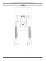
1
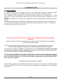
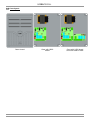
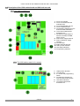
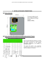
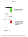
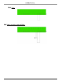
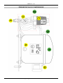
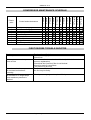
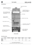
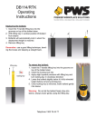
INSTALLATION AND MAINTENANCE GUIDE
FOR STANDARD
MICRO TECHNICAL CENTRES
Article Code: CCE0011PU
THIS MANUAL IS INTENDED FOR FOREMEN AND TECHNICAL STAFF IN CHARGE OF THE
INSTALLATION, OPERATION AND MAINTENANCE OF THIS PRODUCT.
ELECTRIC SHOCK
HAZARD
Do not spill oil! The technical centre should be kept upward because it contains an oil
compressor. Read notice carefully before activation.
Pictures are not contractual
NT-CCE0011PU(V1-EN) – V1 – 12/06
THIS DOCUMENT CONTAINS INFORMATION PROPRIETARY TO URBACO S.A. - FRANCE AND MAY NOT BE REPRODUCED OR USED
IN WHOLE OR PART WITHOUT THE EXPRESS WRITTEN PERMISSION OF URBACO S.A. - FRANCE
URBACO S.A.
CONTENT
Installation and Maintenance Guide for the Standard Micro Technical Centre
1. GENERAL FEATURES....................................................................................................................... 3
1.1. Introduction ................................................................................................................................ 3
1.2. Mechanical specifications (cabinet)............................................................................................. 4
1.3. Electrical specifications............................................................................................................... 4
1.4. Contraindications ........................................................................................................................ 4
2. HOW TO INSTALL THE TECHNICAL CENTRE................................................................................. 5
3. CONNECTION AND ACTIVATION OF THE MICRO TECHNICAL CENTRE...................................... 6
3.1. Programming and tuning............................................................................................................. 6
3.2. 1st Energization ......................................................................................................................... 6
User’s manual for the URBACO U200 and U201 control boards
User’s manual for basic horizontal oil-lubricated compressor
URBACO
-2-
Installation and Maintenance Guide for Standard Micro Technical Centres
1. GENERAL FEATURES
The U200 micro-technical centre with oil compressor is intended for the operation of URBACO
pneumatic retractable bollards.
Remote controls, to be ordered separately, will actuate the bollards down.
The number of bollards is limited on the one side hand by the maximal power released by the U200
control board (4 solenoids max.) and on the other side by the compressor capacity to supply air to the
bollards (see table chart in compressor notice).
As an option, the technical centre can run a 2nd access.
The cabinet containing the technical centre is made of metal; its base has been bored in advance (cable
gland).
It is designed for wall mount with anchor clips (supplied).
1.1. Introduction:
The cabinet is naturally ventilated.
As a standard, it integrates a perforated grid on which the U200 case is fixed (1) ; the compressor is
positioned in the lower part of the cabinet (2) and as an option, the add-on card for the 2nd access, the
heater, control actuators built-in and operation logic apparels.
A
1
A
2
URBACO
-3-
URBACO S.A.
1.2. Mechanical specifications (cabinet):
Dimensions: Height 600 x Width 400 x Depth 250
Working depth: 230mm
Material: Steel
Thickness: 1.5mm
Weight: ~28 kg
Surfacing process: Phosphatation, neutralisation, passivation, neutralisation and polyester coating of
60µm by electro-static powdering.
Protection degree: IP 44
Shock index: IK 10 (1kg at 50cm)
Insulation: Class I
Ventilation: natural
Door: 1 plain steel door
Closing: handle with 2-point lock and key (Ref. N°2 433A (2 keys are supplied)
Maximal load with anchor clips supplied: 100kg
Behaviour of cabinets depending on their surroundings
Dry
Humid
Excellent Excellent
Environment
Outside
Inside
Very
Humid
Rural
Urban
Industrial
Tropical
Marine
Cold
Very
cold
Temperate
Hot and
dry
Equatorial
Good
Excellent
Very
good
Very
good
---
---
Very
good
---
Excellent
Excellent
---
1.3. Electrical specifications:
Voltage: 230V 1-phased 16A + Earth
Power: about 500W
Operation intermittence: 50%
Ambient temperature outside: -10°C (with heating sy stem, available on option) to +40°C
Caution! It is of paramount importance that the micro technical centre is earthed before
being activated.
1.4. Contraindications:
The U200 micro technical centre and its basic compressor are designed for non-intensive use. The
maximum duration of non-stop operation is 15 minutes, followed by a pause of 15 minutes.
This system is suited for the management of control actuators by dry contact, of URBACO limit switches,
of induction loops and of compressor surveillance.
URBACO
-4-
Installation and Maintenance Guide for Standard Micro Technical Centres
2. HOW TO INSTALL THE TECHNICAL CENTRE
Use the set of 4 x wall-mount pegs supplied.
Place the cabinet indoor or outdoor against a wall (garage, technical
shed/room…) as close as possible to the access site.
Even if the level of noise is low (< 50 dB), the installation of the technical
centre is not to be envisaged inside an office where people are meant to be
working.
Some cabinets have thermal insulation.
Leave enough room around the cabinet to ensure proper cooling.
The door must be locked with a key and kept out of the reach of children.
Wall-mounting
is ensured with 4 x pegs screwed on the cabinet, either
horizontally or vertically, but in any case the cabinet must
be positioned vertically. The pegs are fixed to the wall with
concrete anchors (or similar), not supplied.
Cabinets
Height
Width
(mm)
(mm)
500
400
600
400
600
600
Vertical pegs
R(mm)
550
650
650
S(mm)
350
350
550
Horizontal pegs
T(mm)
450
550
550
URBACO
U(mm)
450
450
650
Cabinet + Pegs
V(mm)
602
702
702
Y(mm)
502
502
702
-5-
URBACO S.A.
3. CONNECTION AND ACTIVATION OF THE MICRO TECHNICAL CENTRE
Before operating, make sure the compressor filter is duly positioned.
The compressor is not delivered ready for use (see compressor manual).
Once all the wiring is done and all flexible tubing is connected, to/from the bollard to/from the cabinet,
proceed as follows for activation (see technical data sheet for Micro Technical Centre for connections).
For reasons of safety, the cable for power supply cable will be connected at the last moment
by a professional electrician. A 30 mAmp ground fault circuit interrupter must be installed.
It is imperative that the City3 controller be earthed.
All connections must be done with power TURNED OFF.
For the first activation, it is strongly recommended to close the access location with
appropriate means to prevent vehicle driving through. This is to avoid any hazard or accident
in case something is not properly connected.
3.1. Programming and tuning:
Programme the U200 control board as per requirements (see §4 in the U200 manual).
3.2. 1st Energization:
Turn compressor ON.
If loops have been laid around the bollard for safety reasons, remove any metallic object if placed over
the loops so as not to disturb the detector.
Energize the micro technical centre and look around to check the bollard perimeter (nobody
and no vehicle around).
Program radio transmitters*.
Reset detector to initialize it* (no metallic object should be placed over the loops during the process.
*: depending on equipment within the technical centre.
See §5 in the U200 manual to proceed with operation tests.
All safety functions must be controlled with all due attention.
Once the operation has been validated in real conditions (with vehicles driving through), access site may
be opened for traffic.
URBACO
-6-
USER’S MANUAL – URBACO U200 &
U201 CONTROL BOARDS
Article Code: 002ZU200
Version V4
THIS MANUAL IS INTENDED FOR FOREMEN AND TECHNICAL STAFF IN CHARGE OF THE
INSTALLATION, OPERATION AND MAINTENANCE OF THIS PRODUCT.
ELECTRIC SHOCK
HAZARD
Pictures are not contractual
NT-U200V4(V3-EN) – V3 – 09/06
THIS DOCUMENT CONTAINS INFORMATION PROPRIETARY TO URBACO S.A. - FRANCE AND MAY NOT BE REPRODUCED OR USED
IN WHOLE OR PART WITHOUT THE EXPRESS WRITTEN PERMISSION OF URBACO S.A. - FRANCE
URBACO S.A.
CONTENT
1. PRESENTATION ................................................................................................................. 3
1.1. General features......................................................................................................... 3
1.2. Case layout ................................................................................................................ 4
1.3. Description of the U200 board and U201 add-on-card ................................................ 5
1.3.1. The U200 motherboard................................................................................... 5
1.3.2. The U201 add-on-card for 2nd access ............................................................ 5
2. TECHNICAL SPECIFICATIONS ........................................................................................... 6
3. INSTALLATION AND CONNECTIONS ................................................................................ 7
3.1. How to fix the case ................................................................................................... 7
3.2. How to connect the U200 motherboard and U201 add-on-card for 2nd access........... 7
3.2.1. Connecting the bollard and its accessories..................................................... 7
3.2.2. Connecting the compressor ............................................................................ 8
3.2.3. Connecting mains supply................................................................................ 8
3.3. How to connect the operation logic system................................................................ 9
3.3.1. Controlled entrance and free exit .................................................................... 9
a) Installation of loops...................................................................................... 9
b) Connecting the detector contacts ................................................................ 9
c) Connecting the loops................................................................................... 9
3.3.2. Controlled entrance and exit ......................................................................... 10
a) Installation of loops.................................................................................... 10
b) Connecting the detector contacts .............................................................. 10
c) Connecting the loops................................................................................. 10
3.3.3. Free exit ....................................................................................................... 11
a) Installation of loops.................................................................................... 11
b) Connecting the detector contacts .............................................................. 11
c) Connecting the loops................................................................................. 11
3.3.4. None ........................................................................................................... 12
3.4. How to connect an external timer ............................................................................. 12
4. PROGRAMMING AND TUNING ........................................................................................ 13
5. OPERATION ..................................................................................................................... 14
5.1. Power on ................................................................................................................ 14
5.2. Power outage ........................................................................................................... 14
5.3. Operation on a descent request (normal passage) .................................................. 14
5.4. Operation in manual mode (rise and descent by controller) ..................................... 14
5.5. Operation of emergency stop .................................................................................. 14
5.6. Operation on a free exit ............................................................................................ 14
5.7. Safety during rise...................................................................................................... 14
5.8. Locking in the upward position.................................................................................. 15
5.9. Operation of compressor surveillance....................................................................... 15
5.10. Compressor management ...................................................................................... 15
5.11. Loss of upper limit switch while bollard locked upward ........................................... 15
5.12. LED status indicators.............................................................................................. 15
5.13. Negative security / Failsafe..................................................................................... 15
5.14. Maximum number of bollards.................................................................................. 15
5.15. Traffic lights indicating bollard status ...................................................................... 15
5.16. Access default ........................................................................................................ 15
6. MAINTENANCE .................................................................................................................. 16
7. TROUBLE SHOOTING ...................................................................................................... 17
URBACO
-2-
User’s manual for the URBACO U200 and U201 control boards
1. PRESENTATION
1.1. General features:
This manual describes the setup and operation of the CAME U200 Version V4 automation board
intended for the management of URBACO’s pneumatic-driven automatic retractable bollards.
As a standard the case consists of the U200 motherboard which runs I access and of a mains
transformer. Using the optional U201 add-on-card connected to the U200 makes it possible to run a 2nd
access.
The detectors/sensors for the safety loops may be built in the case depending on operating logic mode
chosen.
The U200 board has a socket designed for CAME plug-in boards. Programming the board depending
on operating mode selected is done with switches and with a potentiometer. Finally, 4 x LEDs give
indications on the status of some functions.
Directions for the good use of an access site controlled by automatic retractable
bollard(s)
SAFETY RULES FOR THE GOOD USE OF AN ACCESS SITE CONTROLLED BY AUTOMATIC
RETRACTABLE BOLLARD(S)
So as to ensure the good operationality of the access, for safety reasons URBACO recommends:
• To set up vertical signposts warning of an obstacle («retractable bollard») ahead.
For access control systems, URBACO recommends that vehicle be obliged to stop before the bollard
and wait for its complete retraction underground (and for the light to turn from red to flashing amber
if the access site has position lights) prior to driving on.
For access sites programmed with bollards automatically rising once a vehicle has passed, following
vehicles must not try and drive through the access site one after the other without each stopping
before the bollard, making sure it is retracted and respect signal given by position light (if such a
device has been installed).
INFORMATION AND TRAINING OF USERS
The person(s) in charge of the access site is (are) bound to inform users on how to operate and utilise
the access. URBACO will not be held responsible for any damage due to mishandling or to disrespecting
safety rules.
URBACO
-3-
URBACO S.A.
1.2. Case layout:
Case closed
Case with U200
board
URBACO
Case with U200 board
and U201 add-on-card
-4-
User’s manual for the URBACO U200 and U201 control boards
1.3. Description of the U200 motherboard and U201 add-on-card:
1.3.1. The U200 motherboard:
1. Fuse: Line 630 Ma
2. Fuse: Accessories 5A and
solenoid valve
3. Fuse: Motherboard 315 mA
4. Fuse: Compressor 5A T
5. Programming switches for CH1
and CH2 radio transmitters
6. Time control setter before
automatic rise
7. Sockets for CAME plug-ins:
AF43S, AF43SM, AF43SR,
AF30, AF150
8. 230V mains supply terminal
9. 230V compressor supply
terminal
10. Terminal strip
11. Radio antenna terminal
12. U201 junction terminal
13. LED status indicators
14. Programming switches
1.3.2. The U201 add-on-card for 2nd access
1. U200 junction terminal
2. Terminal strip
nd
3. 2 access site programming
switch
4. Programming switches for
CH1 and CH2 radio beepers
5. LED status indicators
6. Time lapse relay before
automatic rise
URBACO
-5-
URBACO S.A.
2. TECHNICAL SPECIFICATIONS
General specifications:
Case:
IP:
IK:
Cable input:
Weight:
Dimensions (H x L x D):
:
:
:
:
:
:
ABS plastic
IP 54
IK 8
4 inputs for PE Ø10 (not supplied)
3.5 kg // 7.7 lbs
320 mm x 240 mm x 150 mm // 12.6 x 9.44 x 5.9 in.
Electrical specifications:
Supply tension:
Consumption:
Frequency:
Electrical insulation:
:
:
:
:
230 V, 1-phase
<1A (U200 only)
50 Hz
Class II
Class I (open case)
Specifications:
URBACO U200 and U201 control boards permit:
•
•
•
•
•
•
From 1 to 4 automatic retractable bollards for the pneumatic version
Management of upper and lower limit switches by URBACO
Management of induction loops via 1- or 2-way detectors (depending on
operating logic mode)
Compressor surveillance
Management of external controllers by dry contact
Operation of 4 solenoid valves (as supplied by URBACO)
A maximum power of 20W is available on Solenoid Valve output.
The U200 and U201 control boards do not have any diagnose for operation faults except for compressor
surveillance.
Limit switches are compatible but no default may be detected or diagnosed.
URBACO
-6-
User’s manual for the URBACO U200 and U201 control boards
3. INSTALLATION AND CONNECTIONS
3.1. How to fix the case:
This case is suitable for wallmount inside any premises or
built in a cabinet or CITY-type
controller
215 mm = 8.46 in
295 mm = 11.61 in
3.2. How to connect the U200 motherboard and U201 add-on-card for 2nd access:
3.2.1. How to connect the bollard and its accessories:
When several bollards are present on 1 access,
apply parallel connections for solenoid valves
and series connections for limit switches.
Compressor surveillance is not available on
U201 add-on-cards.
The upper limit switch is not compulsory
(programming) but highly recommended for the
optimal management of bollards
Compressor surveillance
Upper limit switch(es)
Lower limit switch(es)
Safety contact
Descent or Rise/Descent
actuation
Rise actuation
Input commons
E-stop (emergency stop)
Solenoid valves
Amber light 24 VAC
Red light 24 VAC
Flashing output (24 VAC 25W
max)
Accessories mains supply (24
VAC 20W max)
Output commons
URBACO
-7-
URBACO S.A.
3.2.2. Connecting the compressor:
This supply terminal permits to
disconnect the compressor in case of
extensive use if the compressor
surveillance contact is connected.
Motor Compressor
230 V 1-phased
3.2.3. Connecting mains supply:
Obligatory use differential protection
30mA for 230V 16A power supply.
Earth/ground wire of power supply
must be connected to all components
with earth/ground connectors.
The controller metal body must be
earthed/grounded when the U200 not
protected with cover.
Mains supply 230V
1-phased 16A
URBACO
-8-
User’s manual for the URBACO U200 and U201 control boards
3.3. How to connect the operation logic system:
3.3.1. Controlled entrance and free exit:
a) Installation of loops:
Bollard
Presence
/ safety
loop N°1
Safety
loop N°2
Controlled Entrance CE
Free exit
loop
Free Exit FE
b) Connecting the detector contacts (sensors):
c) Connecting the loops:
Loop B3
Loop B1
Loop B2
D1: 2-way safety loop detector (B1
and B2)
D2: 1-way free exit loop detector
URBACO
-9-
URBACO S.A.
3.3.2. Controlled entrance and exit:
a) Installation of loops:
Presence
/
safety
loop N°1
Bollard
Presence
/ safety
loop N°2
Controlled Entrance CE
Controlled Exit CEx
b) Connecting the detector contacts:
c) Connecting the loops:
Loop B1
Loop B2
D1: 2-way safety loop detector (B1
and B2)
URBACO
- 10 -
User’s manual for the URBACO U200 and U201 control boards
3.3.3. Free exit:
a) Installation of loops:
Bollard
Presence
/ Safety
loop N°2
Safety
loop N°1
Free exit
loop
Free Exit FEx
b) Connecting the detector contacts:
c) Connecting the loops:
Loop B3
Loop B1
Loop B2
D1: 2-way safety loop detector (B1
and B2)
D2: 1-way free exit loop detector
URBACO
- 11 -
URBACO S.A.
3.3.4. None:
3.4. How to connect an external timer:
URBACO
- 12 -
User’s manual for the URBACO U200 and U201 control boards
4. PROGRAMMING AND TUNING
Programming can be done using 5 switches:
SW1
Automatic or manual operated (ON – or – OFF)
ON: Bollard automatically rises once the safety loops (SM1/SM2) are cleared and after
time range set by potentiometer.
OFF: The bollard does not rise even when the safety loops (SM1/SM2) are cleared;
waiting for actuation by control (See SW2)
SW2 Control actuator (descent –or– rise/descent)
ON: Actuation of rise on input N°4 and descent on input N°7
OFF: Actuation of rise / descent on input N°7
SW3
Warning before rise (YES –or– NO)
ON: 3 seconds’ notice before bollard rises
OFF: Warning deactivated
SW4
Type of solenoid valve
ON: Bi-stable solenoid valve
OFF: URBACO mono-stable solenoid valve
SW5
Descent actuator (with –or– without presence)
ON: Descent actuation with presence (SM1/SM2 open)
OFF: Descent actuation without vehicle presence.
Potentiometer 6 is intended to adjust time frame (warning) before the bollard rises. Time frame
can be set on up to 1 minute.
URBACO
- 13 -
URBACO S.A.
5. OPERATION
5.1. Power on: (when all connections are made))
The bollard rises if the board is programmed on automatic and if safety loops are cleared.
5.2. Power outage:
The bollard retracts underground and rises back when power is back on if the board is programmed on
automatic and if safety loops are cleared.
5.3. Operation on a descent request (normal passage):
SW1 = ON and adjustment of warning time frame before bollard rises.
- Descent actuation with presence (SW5=ON)
The descent actuation will only be taken into account if a vehicle is present on presence / safety loop
N°1 (SM1/SM2 open)
In this case, the bollard rises once the safety loops have been cleared (SM1/SM2 closed) and after the
warning time (if SW3 = ON)
- Descent actuation without presence (SW5=OFF)
The bollard retracts immediately each time it is actuated down and rises once the safety loops have
been cleared (SM1/SM2 closed) and after the warning time (if SW3 = ON)
5.4. Operation in manual mode (rise and descent by controller):
SW1= OFF and SW2 = OFF
Input N°7 is where the bollard up and down receives impulses to do so.
An impulse on 7 immediately triggers the bollard down (conditioned by SW5), a second impulse will
trigger the bollard back up if no vehicle is present on the safety loops (SM1/SM2 closed) and after the
warning time (if SW3 = ON).
SW1 = OFF and SW2 = ON
Input N°7 triggers the bollard down and input N°4 t riggers the bollard up.
An impulse on 7 immediately triggers the bollard down (conditioned by SW5), an impulse on N°4 will
trigger the bollard upward if no vehicle is present on the safety loops (SM1/SM2 closed) and after the
warning time (if SW3 = ON).
5.5. Operation of emergency stop mode:
The emergency stop button added to the system will trigger the bollard down. As long as it is pushed
in, the bollard cannot rise. If the button is released, the bollard remains retracted (down). The bollard
needs to be actuated up by remote control to be able to rise again. This operation mode is in
compliance with the ‘machine directive’
5.6. Operation on a free exit:
Wiring a free exit detector to the system is another way to trigger the bollard down. Bollard will rise
again like for a normal drive-through situation.
5.7. Safety during rise:
– Without upper limit switch: securities are active for the 18 seconds’ time lapse relay after
activation of solenoid valve.
– With upper limit switch: securities are active as long as the upper limit switch is not activated.
As a standard, URBACO bollards are equipped with upper and lower limit switches. It is
recommended to have them connected.
URBACO
- 14 -
User’s manual for the URBACO U200 and U201 control boards
5.8. Locking in the upward position:
– Without upper limit switch: after the 18 seconds’ time lapse relay from the moment the solenoid valve
is activated.
– With upper limit switch: securities are active as long as the upper limit switch is not activated.
As a standard, URBACO bollards are equipped with upper and lower limit switches. It is
recommended to have them connected.
5.9. Operation of compressor surveillance:
A dry contact on pressure gauge is used to control time during which compressor is in service. When
motor is on, the contact is closed. When the motor stops, the contact opens. As soon as the solenoid
valve is actuated, time lapse relay starts. If the compressor turns for 5 minutes, operation is stopped.
5.10. Compressor management:
The compressor works on its own. The 230V mains supply is continuous in normal operation. The
pressure gauge built in runs the ‘on’ and ‘off’ status of the compressor to maintain air pressure in circuit.
5.11. Loss of upper limit switch while bollard locked upward:
Does not affect system
5.12. Visualisation LEDs:
ST = ON STOP during rise – OFF Normal
SM = ON SAFETY activated – OFF NORMAL
PROG = Programming of radio beeper
ON = board powered on
5.13. Negative security / Failsafe:
Negative security (failsafe) is meant to maintain the bollard upward in case of a power outage. This
function is not directly managed by the U200 board but this can be done by supplying a counter-valve
between 10 and SR; the counter-valve is placed on the normal solenoid valve exhaust.
5.14. Maximum number of bollards
4 x bollards maximum, whatever the size and diameter.
NB: the type of compressor used also determinates the number of bollards (see documentation on
compressors).
5.15. Traffic lights indicating bollard status
Red light = steady when the bollard is upward
Flashing when the bollard is in motion.
Amber light = flashing when the bollard is down (retracted)
NB: the lower limit switch is imperative for installations using traffic lights.
5.16. Access default
No default management, except for compressor surveillance.
URBACO
- 15 -
URBACO S.A.
6. MAINTENANCE
No special maintenance is prescribed for the U200 ; technical checkups are however advisable to control
the general state of material (absence of dust, humidity…), operationality of safety equipments (vehicle
detection), operationality of control devices (beeper, contactless cards…) and to tighten loose
connections inside the case.
These maintenance interventions are to be envisaged by operators depending where the case is located
and how often it is used (intensive or non-intensive use).
URBACO
- 16 -
User’s manual for the URBACO U200 and U201 control boards
7. TROUBLE SHOOTING
Nature of problem
Solutions
The power LED for is off
- Check power supply with a controller
- Check connections
- Check fuses
Radio beepers not active
- Beepers are not programmed or badly so.
- No vehicle on loop (according to SWS)
- Beeper is out of order
- Radio board
- Antenna
External control
device not active
- Check power and connections.
- Check vehicle presence (SW5)
- Check programming or/and configuration
The bollard does not rise
- SM1/SM2 open
- Time lapse relay for automatic rise is not over
- Board is programmed for manual operating (SW2)
The bollard does not rise
even when power is on
- Try impulse on N°7
- SM1/SM2 open
Traffic lights are not working
correctly
- Check connections of limits switches
(they may have been inverted)
Compressor does not start
- Check fuses
- Check connections
- Check compressor
URBACO
- 17 -
URBACO S.A.
Type: 002ZU200V4
This edition: September 2006
URBACO S.A. - Z.A. du Couquiou 84320 ENTRAIGUES - FRANCE
International calls: +33 490 480 800 Fax: +33 490 480 088
E-mail: [email protected]
URBACO
- 18 -
U SER ’S M A N U A L
B A SIC H O R IZ O N T A L O IL - L U B R IC A T ED
M IC R O C O M PR ESSO R
R e f e r e n c e : R C M PB H
THIS MANUAL IS INTENDED FOR TECHNICAL STAFF IN CHARGE OF
THE INSTALLATION, THE OPERATION AND THE MAINTENANCE OF THIS PRODUCT
CAUTION!
THIS COMPRESSOR IS NOT DELIVERED READY FOR USE.
THE COMPRESSOR COVER PLUG MUST BE REPLACED BY INLET FILTER
(SEE § INSTALLATION)
CAUTION!
ELECTRICAL SHOCK
HAZARD
BEWARE OF
HOT PARTS!
Do not remove
cover from box
when power is on
CAUTION!
KEEP UPRIGHT
OIL SPILLING
HAZARD
Pictures are not contractual
NT-RCMPBH(V2-EN) – V2 – 06/06
URBACO – S.A.
PRESENTATION OF COMPRESSOR
Engineering Division – URBACO
-2-
User’s Manual – Basic horizontal oil-lubricated micro-compressor
Keys to the basic horizontal oil-lubricated micro-compressor:
A
B
C
D
E
Oil level
Oil filler plug
Pressure switch
Pressure gauge
Pneumatic connection
SPARE PARTS
1
3
Complete micro-compressor with oil
Inlet (/suction) filter
1
1
RCMPBH
For spare parts not listed above, please consult Technical Sales Support
Engineering Division – URBACO
-3-
URBACO – S.A.
DESCRIPTION
GENERAL FEATURES
URBACO’s RCMPBH compressor is intended for the supply of compressed air to URBACO’s
automatic bollards with pneumatic cylinders. Its size and the lightweight materials used make it
easy to integrate inside any cabinet.
This compressor presents all control and air circuit elements (pressure gauge, manometer, safety
valve, air vent, air filter, etc).
CONDITIONS OF USE
This compressor is intended for non intensive use.
Maximum continuous operation for 15 minutes, followed by 15 minutes’ without operation.
SPECIFICATIONS
GENERAL SPECS:
• Micro-compressor, oil-lubricated,
• Horizontal model (do not turn upside down!),
• For non intensive use,
• No air reserve,
• No compressor surveillance contact.
• Protection index: IP 44
• Dimensions (L x D x H) : 360 x 250 x 180 mm //14 x 10 x 7 in.
• Weight: 13 kg
• Temperature range for use: 0°C to +50°C // +32°F to +122°F
• Compressor environment:
- Suitable supply voltage
- Well sealed ducts
- Always use in clean, dry and well ventilated area
- Compressor to be fixed by 4 cross-braces on smooth and
stable surface.
ELECTRICAL SPECS:
• Supply voltage: 230V~ 1-phased
• Frequency 50Hz
• Amps: 1.12A
• Motor power: 200W
PNEUMATIC SPECS:
• Flow at 0 bar: 30L/min
• Maximum pressure tolerance: 8 bars (pressure on duty: 5.5 bar)
• Oil type: Mobil RARUS 424
• Oil volume: 480cc
Engineering Division – URBACO
-4-
User’s Manual – Basic horizontal oil-lubricated micro-compressor
INSTALLATION AND OPERATION
•
•
•
•
•
•
•
•
•
All micro-compressors must absolutely be handled horizontally Do not lay on side to prevent
oil spilling and motor deterioration hazard.
All micro-compressors has been tested and inspected at the factory and supplied in perfect
condition. Modifications can be made by qualified technical personnel only.
Prior to commissioning, ensure that mains voltage and frequency as well as cable ends are
suitable for the compressor delivered.
Fix micro-compressor on the appropriate horizontal stand.
Attention! Always maintain
compressor upright.
Replace cover plug by inlet (/suction) filter (See diagram, N°3).
Check oil level (as shown on diagram in A), fill in through port opening (B) up to level mark if
necessary.
Pneumatic connection: (as shown in 3) with a flexible air tube (outer diameter: 10 mm).
Wiring: (as shown in E), with mandatory 30Ma ground fault circuit interrupter (GFCI) and 5 Amp
aM fuse protection (temporised motor drive).
Turn compressor on and check duty pressure on pressure gauge (D). It must be set on 5.5 bar. If
necessary, set pressure by turning pressure switch clockwise or anti-clockwise (as shown in C).
Engineering Division – URBACO
-5-
URBACO –S.A.
1
2
3
4
5
6
7
8
9
Check pressure gauge
Check motor fixings
Check compressor fixings
Check pressure switch
Check air filter
Replace air filter
Check oil level
Change oil
Check for potential air leaks
FIRST DEGREE TROUBLE SHOOTER
Fault
The compressor will not start
The compressor runs but pressure
does not rise
Power is on, but the compressor
will not start and makes a
humming.
Power is on but the compressor
will not start or no longer stops
when maximum pressure is
reached
Explanations / Solutions
Check 220V supply
Check fuse
Check that anti-return valve is not blocked (which is the most
common explanation)
Check that inlet (/suction) filter is not blocked.
Check for leak on connections
The piston may be worn.
Temperature is below 0°C
Air vent may be faulty.
Check pressure gauge and replace if faulty.
Engineering Division – URBACO
-6-
12th month
11th month
10th month
9th month
8th month
7th month
6th month
5th month
4th month
3rd month
Control and maintenance
2nd month
Checkpoint
1st month
COMPRESSOR MAINTENANCE SCHEDULE
User’s Manual – Basic horizontal oil-lubricated micro-compressor
WIRING
Mains Supply 230V
Compressor
Earth / Ground
Live
Neutral
Earth / Ground
Live
Neutral
Engineering Division – URBACO
-7-
INTERNATIONAL SALES DEPARTMENT:
Available Monday through Friday from 8:00 a.m. till 12:30 and from 2:00 p.m. till 6:00 p.m. (local time)
+33 490 480 800
Type: RCMPBH
This Edition: June 2006
URBACO S.A. - Z.A. du Couquiou 84320 ENTRAIGUES – FRANCE
International calls: +33 490 480 800 Fax: +33 490 480 088
E-mail: [email protected]
Installation and Maintenance Guide for Standard Micro Technical Centres
URBACO
7
URBACO S.A.
Type: CCE0011PU
---------------------------URBACO S.A. - Z.A. du Couquiou 84320 ENTRAIGUES - FRANCE
International calls: +33 490 480 800 Fax: +33 490 480 088
E-mail: [email protected]
URBACO
8