1
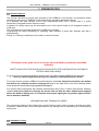
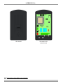
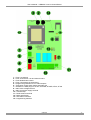
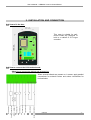
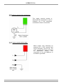
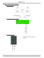
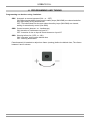
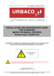
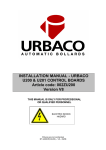
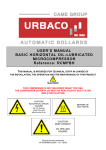
USER’S MANUAL – URBACO U100
CONTROL BOARD
Article Code: 002ZU100
Version V4
THIS MANUAL IS INTENDED FOR FOREMEN AND TECHNICAL STAFF IN CHARGE OF
THE INSTALLATION, OPERATION AND MAINTENANCE OF THIS PRODUCT.
CAUTION!
ELECTRIC
SHOCK HAZARD
Pictures are not contractual
NT-U100V4(V2-EN) – V2 – 06/06
THIS DOCUMENT CONTAINS INFORMATION PROPRIETARY TO URBACO S.A. - FRANCE AND MAY NOT BE REPRODUCED OR USED
IN WHOLE OR PART WITHOUT THE EXPRESS WRITTEN PERMISSION OF URBACO S.A. - FRANCE
URBACO S.A.
SOMMAIRE
1. PRESENTATION ................................................................................................................... 3
1.1. General features........................................................................................................... 3
1.2. Installation of U100 box ................................................................................................ 4
1.3. Description of the U100 control board .......................................................................... 5
2. TECHNICAL SPECIFICATIONS ............................................................................................ 6
3. INSTALLATION & CONNECTIONS ...................................................................................... 7
3.1. How to fix the box ....................................................................................................... 7
3.2. How to connect the U100 motherboard....................................................................... 7
3.2.1. How to connect the bollard and accessories.................................................... 7
3.2.2. How to connect compressor............................................................................. 8
3.2.3. How to connect mains supply........................................................................... 8
3.3. How to connect safety functions ................................................................................. 9
a) Installation of loops ....................................................................................... 9
b) How to connect detector contacts................................................................. 9
c) Connecting the loops .................................................................................... 9
d) No safety function ....................................................................................... 10
4. PROGRAMMING AND TUNING .......................................................................................... 11
5. OPERATION ........................................................................................................................ 12
5.1. Power on .................................................................................................................. 12
5.2. Power outage ............................................................................................................. 12
5.3. Operation on a descent actuation (normal passage)................................................. 12
5.4. Operation in manual mode (rise and descent actuated by remote control)............... 12
5.5. Operation of emergency stop ................................................................................... 12
5.6. Safety during rise ....................................................................................................... 12
5.7. Locking the bollard upward ........................................................................................ 12
5.8. Operation of compressor surveillance ........................................................................ 13
5.9. Compressor control .................................................................................................... 13
5.10. LED status indicators ............................................................................................... 13
5.11. Maximum number of bollards ................................................................................... 13
5.12. Access defaults ........................................................................................................ 13
6. MAINTENANCE ................................................................................................................... 14
7. TROUBLE SHOOTING ........................................................................................................ 15
URBACO
-2-
User’s Manual – URBACO U100 V4 Control Board
1. PRESENTATION
1.1. General features:
This manual describes the setup and operation of the URBACO U100 Version V4 automation board
intended for the control of URBACO’s pneumatic-driven automatic retractable bollards.
As a standard the case consists of the U100 motherboard which runs 1 access and of a mains
transformer (integrated into the electronic card).
A detector for safety loops may be associated to the U100 control board (to be integrated outside of
U100 box).
The U100 board has a socket designed for CAME plug-in boards.
Programming the board depending on operating mode selected is done with switches and with a
potentiometer.
Finally, 4 x LEDs give indications on the status of some functions.
Directions for the good use of an access site controlled by automatic retractable
bollard(s)
SAFETY RULES FOR THE GOOD USE OF AN ACCESS SITE CONTROLLED BY AUTOMATIC
RETRACTABLE BOLLARD(S)
So as to ensure the good operationality of the access, for safety reasons URBACO recommends:
• To set up vertical signposts warning of an obstacle («retractable bollard») ahead.
For access control systems, URBACO recommends that vehicle be obliged to stop before the bollard
and wait for its complete retraction underground (and for the light to turn from red to flashing amber
if the access site has position lights) prior to driving on.
For access sites programmed with bollards automatically rising once a vehicle has passed, following
vehicles must not try and drive through the access site one after the other without each stopping
before the bollard, making sure it is retracted and respect signal given by position light (if such a
device has been installed).
INFORMATION AND TRAINING OF USERS
The person(s) in charge of the access site is (are) bound to inform users on how to operate and utilise
the access. URBACO will not be held responsible for any damage due to mishandling or to disrespecting
safety rules.
1.2. Installation of box:
URBACO
-3-
URBACO S.A.
Box with U100
control board
Box closed
1.3. Description of the U100 control board:
URBACO
-4-
User’s Manual – URBACO U100 V4 Control Board
1 – Fuse: Line 630mA
2 – Fuse: Accessories 1.6A and solenoid valve
3 – Fuse: Motherboard 315mA
4 – Fuse: Compressor 5A temporised
5 – Programming switches for CH1 radio beepers
6 – Time lapse control switch before automatic rise
7 – Sockets for CAME plug-ins: AF43S, AF43SM, AF43SR, AF30, AF150
8 – 230V mains voltage terminal
9 – 230V compressor supply terminal
10 – Terminal strip
11 – Radio antenna terminal
12 – Mains transformer
13 – LED status indicators
14 – Programming switches
URBACO
-5-
URBACO S.A.
2. TECHNICAL SPECIFICATIONS
General specifications:
Box
IP
IK
Cable inputs
:
:
:
:
Weight
Dimensions (H x L x D)
:
:
ABS plastic
IP 54
IK 8
2 inputs for PE Ø10 (not supplied)
1 input for PE Ø6 (not supplied)
1.3 kg
320 x 240 x 150 mm
Electrical specification:
Mains voltage
Consumption
Frequency
Electrical insulation
:
:
:
:
230 V 1-phase
<1A (U100 only)
50 Hz
class II
Specifications:
The U100 control board permits:
• Up to 2 automatic retractable bollards for the pneumatic version
• Control of induction loops via 1- or 2-channel detectors (depending on operating logic
mode)
• Compressor surveillance
• Control of external actuators by dry contact
• Operation of 2 solenoid valves (as supplied by URBACO)
A maximum power of 20W is available on Solenoid Valve output.
The U100 control board is not compatible with either limit switches and/or bollard status indicators
(position lights).
URBACO
-6-
User’s Manual – URBACO U100 V4 Control Board
3. INSTALLATION AND CONNECTION
3.1. How to fix the box:
This case is suitable for wallmount inside any premises or
built in a cabinet or CITY-type
controller.
3.2. How to connect the U100 motherboard:
3.2.1. How to connect the bollard and accessories:
When several bollards are present on 1 access, apply parallel
connections for solenoid valves and series connections for
limit switches.
Compressor surveillance
Safety contact
Rise actuation
Input commons
Emergency stop
Solenoid valve(s)
Output ‘Bollard in motion’
Accessories (24VAC 20W mai)
Output commons
URBACO
-7-
URBACO S.A.
3.2.2. How to connect the compressor:
This supply terminal permits to
disconnect the compressor in case of
extensive use if the compressor
surveillance contact is connected.
Motor Compressor
230 V 1-phase
3.2.3. How to connect mains supply:
Mains supply must absolutely be
protected by a GFCI (ground fault
circuit interrupter) 16A 30 mA. The
earth / ground wire will be connected
to
compressor
supply.
The
compressor is the only appliance to
be earthed / grounded.
Mains supply
230V 1-phase
16A
URBACO
-8-
User’s Manual – URBACO U100 V4 Control Board
URBACO
-9-
URBACO S.A.
3.3. How to connect the safety functions:
a) Installation of loops:
Bollard
Safety
Loop N°2
Safety
Loop N°1
Controlled Entrance
Controlled Exit
b) Connecting the detector contacts:
c) Connecting the loops:
D1: Socket for B1 & B2 safety loop
detectors
Loop B1
Loop B2
D1
URBACO
- 10 -
User’s Manual – URBACO U100 V4 Control Board
d) No safety function:
URBACO
- 11 -
URBACO S.A.
4. PROGRAMMING AND TUNING
Programming can be done using 3 switches:
SW1 Automatic or manual operated (ON – or – OFF)
ON: Bollard automatically rises once the safety loops (SM1/SM2) are cleared and after
time lapse delay set by potentiometer.
OFF: The bollard does not rise even when the safety loops (SM1/SM2) are cleared;
waiting for actuation by control (See SW2)
SW2 Control actuator (descent –or– rise/descent)
ON: Actuation of rise/descent on input N°7
OFF: Actuation of rise on input N°4 and descent on input N°7
SW3 Warning before rise (YES –or– NO)
ON: 3 seconds’ notice before bollard rises
OFF: Warning deactivated
Potentiometer 6 is intended to adjust time frame (warning) before the bollard rises; Time frame
between 0 and 2 minutes.
URBACO
- 12 -
User’s Manual – URBACO U100 V4 Control Board
5. OPERATION
5.1. Power on: (when all connections are made)
The bollard rises if the board is programmed on automatic and if safety loops are cleared.
5.2. Power outage:
The bollard retracts underground and rises back when the power is back if the board is programmed
on automatic and if safety loops are cleared.
5.3. Operation on a descent actuation (normal passage):
SW1 = ON / SW2 = ON and setting of time lapse delay before bollard rises back:
- A descent actuation will immediately trigger the bollard down.
- The bollard will be considered ‘down’ (retracted) after 18 seconds’ time lapse delay.
- The bollard then rises back depending on:
- The 18 seconds’ time lapse is over.
- Loops (SM1/SM2 closed) are cleared.
- Trimming before bollard rises.
- Notification time (depending on SW3).
SW1 = ON / SW2=OFF and setting of time lapse delay before bollard rises back:
- A descent actuation will immediately trigger the bollard down.
- The bollard will be considered ‘down’ (retracted) after 18 seconds’ time lapse delay.
- The bollard then rises back depending on:
- A rise actuation (command) (on 7).
- The 18 seconds’ time lapse before descent is over.
- Loops (SM1/SM2 closed) are cleared.
- Trimming before bollard rises.
- Notification time (depending on SW3).
5.4. Operation in manual mode (rise and descent actuated by remote control):
SW1 = OFF and SW2 = OFF
Input N°7 is where the bollard receives impulses to go up and down.
An impulse on 7 immediately triggers the bollard down, a second impulse on 7 will trigger the bollard
back up if no vehicle is present on the safety loops (SM1/SM2 closed) and after time lapse delay and
pre-warning time.
5.5. Operation of emergency stop:
The emergency stop button added to the system will trigger the bollard down. As long as it is pushed
in, the bollard cannot rise. If the button is released, the bollard remains retracted (down). The bollard
needs to be actuated up by remote control to be able to rise again. This operation mode is in
compliance with the ‘machine directive’.
5.6. Safety during rise:
Safety devices are active during time lapse delay of 18 seconds once the solenoid valve is activated.
After that time lapse delay, the bollard is considered upward.
5.7. Locking the bollard upward:
After 18 seconds as from activation of solenoid valve
URBACO
- 13 -
URBACO S.A.
5.8. Operation of compressor surveillance:
A dry contact from pressure switch is used to control operation time of compressor.
When the motor is on, the contact is closed.
When the motor stops, the contact opens.
As soon as the solenoid valve is activated, time lapse delay starts.
If the compressor runs for 5 minutes, operation stops.
5.9. Compressor control:
Compressor works on its own.
230V voltage supply is permanent in normal operation.
The pressure switch on the compressor will control start/stop to maintain air pressure within circuit.
5.10. LED status indicators:
ST = Switched on ⇒ STOP during rise – Switched off ⇒ normal
SM = Switched on ⇒ SAFETY activated – Switched off ⇒ NORMAL
PROG = radio beeper programming
ALIM = Switched on ⇒ power is on (card)
5.11. Maximum number of bollards:
2 BOLLARDS, no matter the diameter and height.
Note: the type of compressor used also determinates the number of bollards (see table chart)
5.12. Access default:
No default control is done, except for compressor surveillance.
URBACO
- 14 -
User’s Manual – URBACO U100 V4 Control Board
6. MAINTENANCE
No special maintenance is prescribed for the U100. Technical checkups are however recommended
every now and then to control the overall state of equipment (dust, moisture…), safety elements (vehicle
detection, sensors), operationality of actuators (beepers, contactless cards…) as well as to tighten loose
bolts and nuts if necessary.
Periodicity of checkups is left to operator’s judgement depending on where the system is installed and
how often it is on duty (intensive use or not).
URBACO
- 15 -
URBACO S.A.
7. TROUBLE SHOOTING
Problem
Solutions
Power LED is off
- Check power is on
- Check connections
- Check fuses
Radio beepers
not active
- Beepers are not/ badly programmed
- No vehicle detected over loop (according to SWS)
- Beeper is out of order
- Radio card
- Antenna
External actuator
Not active
- Check power input and connections
- Check programme and/or configuration
Bollard remains down
- SM1/SM2 open
- Time lapse delay before automatic rise is not over
Bollard remains down
when power is turned on
- Operate command/actuation on 7
- SM1/SM2 open
Compressor will not start
- Check fuses
- Check connections
- Check compressor
URBACO
- 16 -
User’s Manual – URBACO U100 V4 Control Board
INTERNATIONAL SALES DEPARTMENT:
Available Monday through Friday from 8:00 a.m. till 12:30 and from 2:00 p.m. till 6:00 p.m. (local time)
+33 490 480 800
Type: 002ZU100V4
First released: 2006
URBACO S.A. - Z.A. du Couquiou 84320 ENTRAIGUES – FRANCE
International calls: +33 490 480 800 Fax: +33 490 480 088
E-mail: [email protected]
URBACO
- 17 -