1
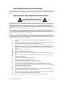
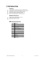
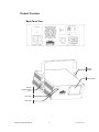
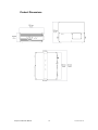
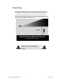
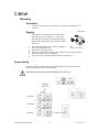
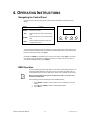
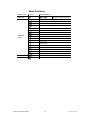
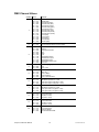
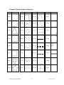
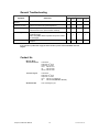
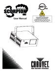
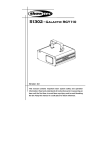
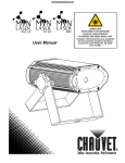
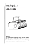
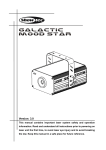
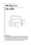
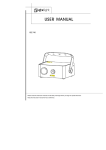
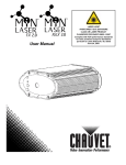
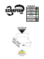
Snapshot Use on Dimmer Outdoor Use Sound Activated DMX Master/Slave Auto-ranging Power Supply Replaceable Fuse User Serviceable Duty Cycle User Manual 3000 N 29th Ct, Hollywood, FL 33020 U.S.A. (800) 762-1084 – (954) 929-1115 FAX (954) 929-5560 www.chauvetlighting.com TABLE OF CONTENTS 1. BEFORE YOU BEGIN ................................................................................................................................................... 3 WHAT IS INCLUDED ................................................................................................................................................................................ 3 UNPACKING INSTRUCTIONS .................................................................................................................................................................... 3 AC POWER........................................................................................................................................................................................... 3 SAFETY INSTRUCTIONS .......................................................................................................................................................................... 4 NON-INTERLOCKED HOUSING WARNING ..................................................................................................................................... 5 LASER SAFETY AND OPERATING INSTRUCTIONS ...................................................................................................................... 5 LASER EMISSION DATA ................................................................................................................................................................... 7 LASER EXPOSURE WARNING ............................................................................................................................... 7 2. INTRODUCTION ........................................................................................................................................................... 8 FEATURES ............................................................................................................................................................................................ 8 ADDITIONAL FEATURES .......................................................................................................................................................................... 8 DMX CHANNEL SUMMARY ..................................................................................................................................................................... 8 PRODUCT OVERVIEW............................................................................................................................................................................. 9 Back Panel View ....................................................................................................................................................... 9 PRODUCT DIMENSIONS ........................................................................................................................................................................ 10 PROPER USAGE .................................................................................................................................................................................. 11 3. SETUP ........................................................................................................................................................................ 12 MOUNTING.......................................................................................................................................................................................... 12 Orientation .............................................................................................................................................................. 12 Rigging ................................................................................................................................................................... 12 Power Linking ......................................................................................................................................................... 12 4. OPERATING INSTRUCTIONS .................................................................................................................................... 13 NAVIGATING THE CONTROL PANEL........................................................................................................................................................ 13 DMX OPERATION................................................................................................................................................................................ 13 STANDALONE OPERATION .................................................................................................................................................................... 14 Automatic ................................................................................................................................................................ 14 Sound-Active .......................................................................................................................................................... 14 Laser Sky ................................................................................................................................................................ 14 MASTER/SLAVE OPERATION................................................................................................................................................................. 14 MENU FUNCTIONS ............................................................................................................................................................................... 15 DMX CHANNEL VALUES ...................................................................................................................................................................... 16 Channel 2 Values (Pattern Selection)...................................................................................................................... 17 5. APPENDIX .................................................................................................................................................................. 18 RETURNS PROCEDURE ........................................................................................................................................................................ 18 CLAIMS .............................................................................................................................................................................................. 18 SETTING THE STARTING ADDRESS ........................................................................................................................................................ 18 GENERAL TROUBLESHOOTING .............................................................................................................................................................. 19 CONTACT US ...................................................................................................................................................................................... 19 TECHNICAL SPECIFICATIONS ................................................................................................................................................................ 20 CHAUVET®, 2009, All Rights Reserved Information and specifications in this User Manual are subject to change without notice. CHAUVET® assumes no responsibility or liability for any errors or inaccuracies that may appear in this manual. Scorpion™ GBC User Manual 2 12/17/2009 10:50 AM 1. BEFORE YOU BEGIN What is included 1 x Scorpion™ GBC 1 x Power cable 1 x Warranty Card 1 x User Manual Unpacking Instructions Immediately upon receiving a fixture, carefully unpack the carton, check the contents to ensure that all parts are present, and have been received in good condition. Notify the shipper immediately and retain packing material for inspection if any parts appear damaged from shipping or the carton itself shows signs of mishandling. Save the carton and all packing materials. In the event that a fixture must be returned to the factory, it is important that the fixture be returned in the original factory box and packing. AC Power This fixture has an auto-ranging power supply that can accommodate a wide range of input voltages. The only thing necessary to do before powering on the unit is to make sure the line voltage you are applying is within the range of accepted voltages. This fixture will accommodate between 100~240 VAC, 50/60 Hz. All fixtures must be powered directly off a switched circuit and cannot be run off a rheostat (variable resistor) or dimmer circuit, even if the rheostat or dimmer channel is used solely for a 0% to 100% switch. Scorpion™ GBC User Manual 3 12/17/2009 10:50 AM Safety Instructions Please read these instructions carefully, which includes important information about the installation, usage and maintenance of this product. Please keep this User Manual for future consultation. If you sell the unit to another user, be sure that they also receive this instruction booklet. Always make sure that you are connecting to the proper voltage, and that the line voltage you are connecting to is not higher than that stated on the decal or rear panel of the fixture. This product is intended for indoor use only! To prevent risk of fire or shock, do not expose fixture to rain or moisture. Make sure there are no flammable materials close to the unit while operating. The unit must be installed in a location with adequate ventilation, at least 20 in (50 cm) from adjacent surfaces. Be sure that no ventilation slots are blocked. Always disconnect from power source before servicing or replacing fuse and be sure to replace with same fuse size and rating. Secure fixture to fastening device using a safety chain. Maximum ambient temperature (Ta) is 104° F (40° C). Do not operate fixture at temperatures higher than this. In the event of a serious operating problem, stop using the unit immediately. Never try to repair the unit by yourself. Repairs carried out by unskilled people can lead to damage or malfunction. Please contact the nearest authorized technical assistance center. Never connect the device to a dimmer pack. Make sure the power cord is never crimped or damaged. Never disconnect the power cord by pulling or tugging on the cord. Avoid direct eye exposure to the light source while it is on. Lasers can be hazardous and have unique safety considerations. Permanent eye injury and blindness is possible if lasers are used incorrectly. Pay close attention to each safety REMARK and WARNING statement in the user manual. Read all instructions carefully BEFORE operating this device. Caution! Avoid direct eye contact with laser light. Never intentionally expose your eyes or others to direct laser light. Caution! This laser product can potentially cause instant eye injury or blindness if laser light directly strikes the eyes. Caution! It is illegal and dangerous to shine this laser into audience areas, where the audience or other personnel could get direct laser beams or bright reflections into their eyes. Caution! It is a US Federal offense to shine any laser at aircraft. Caution! Use of controls or adjustments or performance of procedures other than those specified herein may result in hazardous radiation exposure. Caution! There are no user serviceable parts inside the unit. Do not open the housing or attempt any repairs yourself. In the unlikely event your unit may require service, please contact the dealer nearest to you. Scorpion™ GBC User Manual 4 12/17/2009 10:50 AM NON-INTERLOCKED HOUSING WARNING This unit contains high power laser devices internally. Do not open the laser housing, due to potential exposure to unsafe levels of laser radiation. The laser power levels accessible, if the unit is opened, can cause instant blindness, skin burns and fires. LASER SAFETY AND OPERATING INSTRUCTIONS STOP AND READ ALL LASER SAFETY DATA Laser Light is different from any other light sources with which you may be familiar. The light from this product can potentially cause eye injury if not set up and used properly. Laser light is thousands of times more concentrated than light from any other kind of light source. This concentration of light can cause instant eye injuries, primarily by burning the retina (the light sensitive portion at the back of the eye). Even if you cannot feel “heat” from a laser beam, it can still potentially injure or blind you or your audience. Even very small amounts of laser light are potentially hazardous even at long distances. Laser eye injuries can happen quicker than you can blink. It is incorrect to think that because these laser entertainment products split the laser into hundreds of beams that the laser beam is scanned out in high speed, that an individual laser beam is safe for eye exposure. This laser product uses dozens of milliwatts of laser power (Class 3B levels internally) before it splits into multiple beams (Class 3R levels). Many of the individual beams are potentially hazardous to the eyes. It is also incorrect to assume that because the laser light is moving, it is safe. This is not true. Nor, do the laser beams always move. Since eye injuries can occur instantly, it is critical to prevent the possibility of any direct eye exposure. In the laser safety regulation, it is not legal to aim Class 3R lasers in areas which people can get exposed. This is true even if it is aimed below people’s faces, such as on a dance floor. Do not operate the laser without first reading and understanding all safety and technical data in this manual. Always set up and install all laser effects so that all laser light is at least 3 meters (9.8 feet) above the floor on which people can stand. See “Proper Usage” section later in this manual. After set up, and prior to public use, test laser to ensure proper function. Do not use if any defect is detected. Do not use if laser emits only one or two laser beams rather than dozens/hundreds, as this could indicate damage to the diffraction grating optic, and could allow emission of higher laser levels above Class 3R. Do not point lasers at people or animals. Never look into the laser aperture or laser beams. Do not point lasers in areas in which people can potentially get exposed, such as uncontrolled balconies, etc. Do not point lasers at highly reflective surfaces, such as windows, mirrors and shiny metal. Even laser reflections can be hazardous. Never point a laser at aircraft, this is a federal offense. Never point un-terminated laser beams into the sky. Do not expose the output optic (aperture) to cleaning chemicals. Do not use laser if the laser appears to be emitting only one or two beams. Do not use the laser if the housing is damaged, open, or if the optics appear damaged in any way. Never open the laser housing. The high laser power levels inside of the protective housing can start fires, burn skin and will cause instant eye injury. Never leave this device running unattended. The operation of a class 3R laser show is only allowed if the show is controlled by a skilled and welltrained operator, familiar with the data included in this manual. The legal requirements for using laser entertainment products vary from country to country. The user is responsible for the legal requirements at the location/country of use. Always use appropriate lighting safety cables when hanging lights and effects overhead. Scorpion™ GBC User Manual 5 12/17/2009 10:50 AM LASER SAFETY LABEL REPRODUCTION EXPLANATORY, MANUFACTURER’S ID & CERTIFICATION LABEL CAUTION – CLASS 3B LASER RADIATION WHEN OPEN. AVOID EXPOSURE TO BEAM NON INTERLOCKED HOUSING LABEL LASER HAZARD WARNING LABEL LASER APERTURE LABEL Scorpion™ GBC User Manual 6 12/17/2009 10:50 AM LASER EXPOSURE WARNING LASER LIGHT AVOID DIRECT EYE EXPOSURE Further guidelines and safety programs for safe use of lasers can be found in the ANSI Z136.1 Standard “For Safe Use of Lasers”, available from the Laser Institute of America: www.laserinstitute.org. Many local governments, corporations, agencies, military and others, require all lasers to be used under the guidelines of ANSI Z136.1. Laser Display guidance can be obtained via the International Laser Display Association: www.laserist.org. LASER EMISSION DATA LASER CLASSIFICATION CLASS 3R (EQUIV. TO US CLASS IIIA) Green Laser Medium DPSS Nd:YVO4, 532 nm Blue Laser Medium 473 nm, typical Beam Diameter <5 mm at aperture Pulse Data All pulses < 4 Hz (>0.25 sec) Divergence (each beam) <2 mrad Divergence (total light) <160 degrees Laser Power of Each Beam from Aperture* <5 mW *As measured under IEC measurement conditions for classification. LASER COMPLIANCE STATEMENT This laser product complies with EN/IEC 60825-1 Ed 2, 2007-03, and US FDA/CDRH FLPPS via the terms of Laser Notice No. 50 dated June 24, 2007. This laser device is Classified 3R. (Class 3R is the international equivalent of US Class IIIa). No maintenance is required to keep this product in compliance with laser performance standards. Scorpion™ GBC User Manual 7 12/17/2009 10:50 AM 2. INTRODUCTION Features 10-channel DMX-512 controlled green, blue & cyan aerial effect laser Programmable pan, tilt and zoom with separate X, Y, and Z rolling effects 32 built-in pattern selections each with adjustable parameters Color selection of green, blue and/or cyan with strobe control Built-in automatic programs via master/slave or DMX Built-in sound activated programs via master/slave or DMX Additional Features Complies with FDA / CDRH standards for Class 3R Multiple mounting locations for bracket Additional power output: max 20 units DMX Channel Summary CHANNEL FUNCTION 1 Control Mode 2 Pattern Selection 3 Color selection 4 Color Changing Speed 5 Zoom 6 X Axis Move (Pan) 7 Y Axis Move (Tilt) 8 Y Axis Roll 9 X Axis Roll 10 Z Axis Rotate Scorpion™ GBC User Manual 8 12/17/2009 10:50 AM Product Overview Back Panel View Hanging bracket Laser Aperture Bracket adjustment knob (1 of 2) Power LED Audio LED Scorpion™ GBC User Manual 9 12/17/2009 10:50 AM Product Dimensions Scorpion™ GBC User Manual 10 12/17/2009 10:50 AM Proper Usage This fixture has been designed to be hung. It is recommended for safety purposes, your lighting effects are properly mounted using a suitable hanging clamp and safety cable. Items appropriate for safe and effective mounting are easily sourced from your lighting vendor. International laser safety regulations require that lasers must be operated in the fashion illustrated below, with a minimum of 3 meters (9.8 ft) of vertical separation between the floor and the lowest laser light vertically. Additionally, 3 meters of horizontal separation is required between laser light and audience or other public spaces. 3 meters CAUTION: Use of controls, adjustments, or performance of procedures other than what is specified herein may result in hazardous radiation exposure CAUTION: Use of controls, adjustments, or performance of procedures other than what is specified herein may result in hazardous radiation exposure Scorpion™ GBC User Manual 11 12/17/2009 10:50 AM 3. SETUP Mounting Orientation This fixture may be mounted in any safe position, provided there is adequate room for ventilation. Hanging Clamp Rigging It is important never to obstruct the fan or vents pathway. Mount the fixture using, a suitable “C” or “O” type clamp. Adjust the angle of the fixture by loosening both knobs and tilting the fixture. After finding the desired position, retighten both knobs. Note! When selecting installation location, take into consideration Clamp is sold separately. access and routine maintenance. Safety cables must always be used. Never mount in places where the fixture will be exposed to rain, high humidity, extreme temperature changes or restricted ventilation. Do not use any tool on the bracket adjustment knob. Hand-tighten only! Power Linking This fixture contains power linking via the edison outlet located in front of the power input cable. Please see the diagram below for further explanation. The maximum number of fixtures that may be linked for this fixture is 20. Additional power link Fixture #3 Fixture #2 Fixture #1 Scorpion™ GBC User Manual 12 12/17/2009 10:50 AM 4. OPERATING INSTRUCTIONS Navigating the Control Panel Access control panel functions using the four panel buttons located directly underneath the LED Display. Button Function <MODE> Used to access the menu or to return to a previous menu option <UP> Scrolls through menu options in ascending order <DOWN> Scrolls through menu options in descending order <ENT> Used to select and store the current menu or option within a menu MODE UP DOWN ENT The Control Panel LED Display shows the menu items you select from the menu map. When a menu function is selected, the display will show immediately the first available option for the selected menu function. To select a menu item, press <ENT>. Use <UP> and <DOWN> to navigate the menu map and menu options. Press <ENT> to access the menu function currently displayed or to enable a menu option. To return to the previous option or menu without changing the value, press <MODE>. DMX Operation This is the operating mode which will allow for control with an external DMX controller. You must set the starting address for this mode. If this is your first time using DMX, then it is recommended that you refer to the “DMX Primer” section in the “Appendix” of this manual. When operating in DMX receiving mode, the display will blink at a constant rate in the absence of DMX signal. Use the following procedure for setting the fixture to DMX operation. 1. 2. 3. Scorpion™ GBC User Manual Press <MODE> repeatedly until a number from 001~512 appears on the LED display. Use <UP> and <DOWN> to select the DMX starting address. Press <ENT>. 13 12/17/2009 10:50 AM Standalone Operation Automatic This fixture has preprogrammed automatic programs. These are accessed via the LED display on the back panel of the product. Please see the instructions below for further explanation. 1. 2. 3. Press <MODE> until a standalone mode appears on the LED display. See the chart under menu functions to identify these. Use <UP> and <DOWN> to scroll through the standalone modes. Press <ENT> when the desired automatic standalone mode has been located. Sound-Active This fixture has preprogrammed sound-triggered programs. These are accessed via the LED display on the back panel of the product. The sound control adjustment knob may be used to adjust the microphone sensitivity. Please see the instructions below for further explanation. 1. 2. 3. Press <MODE> until a standalone mode appears on the LED display. See the chart under menu functions to identify these. Use <UP> and <DOWN> to scroll through the standalone modes. Press <ENT> when the desired sound standalone mode has been located. Laser Sky This fixture has preprogrammed laser sky programs. These are accessed via the LED display on the back panel of the product. Please see the instructions below for further explanation. 1. 2. 3. Press <MODE> until a standalone mode appears on the LED display. See the chart under menu functions to identify these. Use <UP> and <DOWN> to scroll through the standalone modes. Press <ENT> when the desired laser sky standalone mode has been located. Master/Slave Operation When operating more than one fixture in standalone mode, it is possible to link them in a master/slave configuration. This is when one or more slave fixtures will operate identically to the master fixture. Please see the instructions below for further explanation on how to set a fixture to slave mode. 1. 2. Press <MODE> until slave mode appears on the LED display. See the chart under menu functions to identify this. Press <ENT>. A fixture that is operating in one of the standalone mode will function as a master unit when the fixtures are linked using DMX cables in a daisy chain configuration. Scorpion™ GBC User Manual 14 12/17/2009 10:50 AM Menu Functions MAIN FUNCTION SELECTION DESCRIPTION/VALUES DMX mode DMX starting address assignment Automatic fast (blue) Automatic slow (blue) Automatic fast (green) Automatic slow (green) Automatic fast (cyan) Automatic slow (cyan) Automatic fast (mixed) Standalone modes Automatic slow (mixed) Sound (blue) Sound (green) Sound (cyan) Sound (mixed) Random Laser sky (blue) Laser sky (green) Laser sky (cyan) Laser sky (sound) Slave Mode Slave mode Test Mode Used for service purposes Scorpion™ GBC User Manual 15 12/17/2009 10:50 AM DMX Channel Values CHANNEL VALUE FUNCTION 1 000 017 018 035 036 053 054 071 072 089 090 107 108 125 126 143 144 161 162 179 180 197 198 215 216 233 234 255 Control Mode Manual Mode Automatic fast (blue) Automatic slow (blue) Automatic fast (green) Automatic slow (green) Automatic fast (cyan) Automatic slow (cyan) Automatic Fast (mixed) Automatic Slow (mixed) Sound (blue) Sound (green) Sound (cyan) Sound (mixed) Random (Auto) 2 000 255 Pattern selection (only when CH1 is between 000~017) See the following page for channel values. 000 024 025 049 050 074 075 099 100 124 125 149 150 174 175 199 200 224 225 255 Color selection Blackout Preprogrammed Color Blue Green Cyan Alternate Blue-Green Alternate Green-Cyan Alternate Blue-Cyan Alternate Blue-Green-Cyan Color Roll 4 000 004 005 255 Color Changing Speed Stop Slow fast 5 000 127 128 169 170 209 210 255 Zoom 100%~5% Zoom In Macro Zoom Out Macro Zoom In and Out Macro 6 000 127 128 191 192 255 X-Axis Move (Pan) 128 different positions on Y-Axis Move Left to right to Left (Slow fast) Move Left to right to Left (Fast slow) 7 000 127 128 191 192 255 Y-Axis Move (Tilt) 128 different positions on X-Axis Move Up to down to Up (Slow fast) Move Up to down to Up (Fast slow) 8 000 127 128 191 192 255 X-Axis Roll 0~359 Y-Axis Roll Roll (Slow fast) Roll (Fast slow) 9 000 127 128 191 192 255 Y-Axis Roll 0~359 Y-Axis Roll Roll (Slow fast) Roll (Fast slow) 10 000 127 128 191 192 255 Rotate 0~359 Z-Axis Roll Clockwise Rotate Counterclockwise Rotate 3 Scorpion™ GBC User Manual 16 12/17/2009 10:50 AM Channel 2 Values (Pattern Selection) Value Pattern Value Pattern Value Pattern Value 000~007 064~071 128~135 190~197 008~015 072~079 136~143 198~205 016~023 080~087 144~151 206~213 024~031 088~095 152~159 214~221 032~039 096~103 160~167 222~229 040~047 104~111 168~175 230~237 048~055 112~119 176~181 238~245 056~063 120~127 182~189 246~255 Scorpion™ GBC User Manual 17 Pattern 12/17/2009 10:50 AM 5. APPENDIX Returns Procedure Returned merchandise must be sent prepaid and in the original packing, call tags will not be issued. Package must be clearly labeled with a Return Merchandise Authorization Number (RMA #). Products returned without an RMA # will be refused. Call CHAUVET® and request RMA # prior to shipping the fixture. Be prepared to provide the model number, serial number and a brief description of the cause for the return. Be sure to properly pack fixture, any shipping damage resulting from inadequate packaging is the customer’s responsibility. CHAUVET® reserves the right to use its own discretion to repair or replace product(s). As a suggestion, proper UPS packing or double-boxing is always a safe method to use. Note: If you are given an RMA #, please include the following information on a piece of paper inside the box: 1) Your name 2) Your address 3) Your phone number 4) The RMA # 5) A brief description of the symptoms Claims Damage incurred in shipping is the responsibility of the shipper; therefore the damage must be reported to the carrier upon receipt of merchandise. It is the customer's responsibility to notify and submit claims with the shipper in the event that a fixture is damaged due to shipping. Any other claim for items such as missing component/part, damage not related to shipping, and concealed damage, must be made within seven (7) days of receiving merchandise. Setting the Starting Address This DMX mode enables the use of a universal DMX controller device. Each fixture requires a "start address" from 1 to 512. A fixture requiring one or more channels for control begins to read the data on the channel indicated by the start address. For example, a fixture that uses 6 DMX channels and was addressed to start on DMX channel 100, would read data from channels: 100, 101, 102, 103, 104, and 105. Choose start addresses so that the channels used do not overlap, and note the start address selected for future reference. If this is your first time addressing a fixture using the DMX-512 control protocol, we suggest jumping to the Appendix Section and reading the heading “DMX Primer”. It contains very useful information that will help you understand its use. Scorpion™ GBC User Manual 18 12/17/2009 10:50 AM General Troubleshooting Applies to Symptom Solution(s) Lights Foggers & Snow Controllers Dimmers & Chaser Breaker/Fuse keeps blowing Check total load placed on device Chase is too slow Check user manual for speed adjustment Device has no power Check for power on Mains. Check device’s fuse. (internal and/or external) Loss of signal Use only DMX cables Install terminator Note: Keep DMX cables separated from power cables or black lights. No laser output Bounce mirror motor may have shifted during shipping; readjust If you still have a problem after trying the above solutions, please contact CHAUVET® Technical Support. Contact Us World Wide General Information CHAUVET® 3000 North 29th Court Hollywood, FL 33020 voice: 954.929.1115 fax: 954.929.5560 toll free: 800.762.1084 Technical Support CHAUVET® 3000 North 29th Court Hollywood, FL 33020 voice: 954.929.1115 (Press 4) fax: 954.929.5560 (Attention: Service) World Wide Web www.chauvetlighting.com Scorpion™ GBC User Manual 19 12/17/2009 10:50 AM Technical Specifications WEIGHT & DIMENSIONS Length ........................................................................................................................ 11.3 in (287 mm) Width.......................................................................................................................... 13.4 in (340 mm) Height .......................................................................................................................... 9.1 in (230 mm) Weight........................................................................................................................... 7.8 lbs (3.5 kg) POWER Auto-ranging power supply ..............................................................................100~240 VAC, 50/60 Hz Fuse............................................................................................................ T 1.5 A, 250 V (slow-blow) Power Consumption@ 120 V .................................................................................... 23 W (0.3 A) max Inrush Current@ 120 V ................................................................................................................ 0.3 A Power Consumption@ 230 V .................................................................................... 20 W (0.2 A) max Inrush Current@ 230 V ................................................................................................................ 0.2 A Power Output .................................................................................................................... 20 units max LASER Green diode ................................................................................................................. 532 nm, 30 mW Blue diode .................................................................................................................... 473 nm, 40 mW Laser Type .................................................................................................................................. DPSS Cooling............................................................................................................................... Fan Cooled RANGE Coverage Angle .............................................................................................................................. 53° THERMAL Maximum ambient temperature ...................................................................................... 104° F (40° C) CONTROL & PROGRAMMING Data input ............................................................................................. locking 3-pin XLR male socket Data output ........................................................................................ locking 3-pin XLR female socket Data pin configuration ............................................................................ pin 1 shield, pin 2 (-), pin 3 (+) Protocols .....................................................................................................................DMX-512 USITT DMX Channels .................................................................................................................................. 10 ORDERING INFORMATION Scorpion™ GBC......................................................................................................... SCORPIONGBC WARRANTY INFORMATION Warranty ........................................................................................................... 2-year limited warranty Laser Diode Warranty ...................................................................................... 90-day limited warranty Scorpion™ GBC User Manual 20 12/17/2009 10:50 AM