1
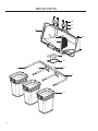
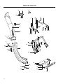
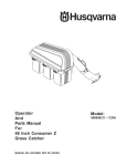
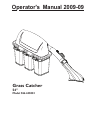
Operator's Manual 2009-09
Grass Catcher
54"
Model 966 445001
©2009 HTC. All Rights Reserved.
Beatrice, NE. Printed in U.S.A.
CONTENTS
Safety...................................................................... 5
GENERAL OPERATION................................. 5
SLOPE OPERATION...................................... 5
CHILDREN.................................................... 6
SERVICE........................................................ 6
Operation............................................................ 14
TIPS TO IMPROVE BAGGING.................... 14
Container Contents.......................................... 8
Customer Responsibilities............................ 15
GENERAL RECOMMENDATIONS............... 15
STORAGE................................................... 15
Assembly................................................................ 9
Parts...................................................................... 16
CONGRATULATIONS on your purchase of a new
Grass Catcher. It has been designed, engineered
and manufactured to give you the best possible
dependability and performance.
Should you experience any problem you cannot
easily remedy, contact the nearest authorized service
center/ department. They have competent, welltrained technicians and the proper tools for service
and repairs.
Read and retain this manual. The instructions will
enable you to assemble and maintain your collection
system properly. Always observe the SAFETY RULES.
WARNING!
Engine exhaust, some of its
constituents, and certain vehicle
components contain or emit
chemicals known to the State of
California to cause cancer and birth
defects or other reproductive harm.
KNOW YOUR GRASS CATCHER
READ THIS OPERATION MANUAL AND SAFETY
RULES BEFORE ASSEMBLING OR OPERATING
YOUR GRASS CATCHER. Compare the illustrations
with the carton contents to familiarize yourself
with the parts before starting the assembly. Study
the operating instructions and safety precautions
thoroughly to insure proper functioning of your Grass
Catcher and to prevent injury to yourself and others.
Save this manual for future reference.
The operation of any mower can result
in foreign objects thrown into the
eyes, which can result in severe eye
damage. ALWAYS wear safety glasses
or eye shields before starting your
mower and while mowing. Standard
safety glasses are recommended or
a wide vision safety mask for over
spectacles.
SAFETY
SAFE OPERATION PRACTICES FOR RIDE-ON MOWERS
DANGER !
THIS CUTTING MACHINE IS CAPABLE OF AMPUTATING HANDS AND FEET
AND THROWING OBJECTS. FAILURE TO OBSERVE THE FOLLOWING
SAFETY INSTRUCTIONS COULD RESULT IN SERIOUS INJURY OR DEATH.
GENERAL OPERATION
•
•
•
•
•
•
•
•
•
•
•
•
•
•
•
•
Read, understand and follow all instructions in the
manual and on the machine before starting.
Only allow responsible adults, who are familiar
with the instructions, to operate the machine.
Clear the area of objects such as rocks, stones,
toys, wire etc., which could be picked up and
thrown by the blades.
Be sure the area is clear of all people and pets
before mowing. Stop the machine if anyone enters
the area.
Never carry passengers or children even with
blades off.
Do not mow in reverse unless absolutely
necessary. Always look down and behind before
and while backing.
Be aware of the mower discharge direction and
do not direct it towards anyone. Do not operate
the mower without either the entire grass catcher
or the guard in place.
Slow down before turning.
Never leave the machine unattended when the
engine is running. Always turn off the blades, set
the parking brake, stop the engine and remove
the key before leaving the machine.
Turn off blades when not mowing.
Stop engine before removing grass catcher or
unclogging chute.
Mow only in daylight or good artificial light.
Do not operate the machine while under the
influence of alcohol or drugs.
Watch out for traffic when operating near or
crossing roadways.
Use extra care when loading and unloading the
machine onto a trailer or truck.
Data indicates that operators, age 60 years and
above, are involved in a large percentage of
riding mower-related injuries. These operators
should evaluate their ability to operate the riding
mower safely enough to protect themselves and
others from serious injury.
•
•
DO NOT operate mower with grass catcher,
unless the front weights are installed.
Keep machine free of grass, leaves or other
debris buildup which can touch hot exhaust/
engine parts and burn. Do not allow the mower
deck to plow leaves or other debris which can
cause buildup to occur. Clean any oil or fuel
spillage before operating or storing the machine.
Allow machine to cool before storage.
SLOPE OPERATION
Slopes are a major factor related to loss-of-control and
tipover accidents, which can result in severe injury or
death. All slopes require extra caution. If you cannot
back up the slope or if you feel uneasy on it, do not
mow it.
DO
•
•
•
•
•
•
•
Mow up and down slopes (10° Max.), not across.
Remove obstacles such as rocks, tree limbs, etc.
Watch for holes, ruts, or bumps. Uneven terrain
could overturn the machine. Tall grass can hide
obstacles.
Use slow speed. Choose a low speed so that you
will not have to stop while on the slope.
Use extra care with grass catchers or other
attachments. These can change the stability of
the machine.
Keep all movement on the slopes slow and
gradual. Do not make sudden changes in speed
or direction.
Avoid starting or stopping on a slope. If tires
lose traction, disengage the blades and proceed
slowly straight down the slope.
5
SAFETY
SAFE OPERATION PRACTICES FOR RIDE-ON MOWERS
DO NOT
•
•
•
•
Do not turn on slopes unless necessary, and then,
turn slowly and gradually downhill, if possible.
Do not mow near drop-off, ditches, or
embankments. The mower could suddenly turn
over if a wheel is over the edge of a cliff or ditch,
or if an edge caves in.
Do not mow on wet grass. Reduced traction
could cause sliding.
Do not try to stabilize the machine by putting your
foot on the ground.
CHILDREN
•
•
•
•
•
•
•
Tragic accidents can occur if the operator is not
alert to the presence of children. Children are
often attracted to the machine and the mowing
activity. Never assume that children will remain
where you last saw them.
NEVER allow children to operate the machine.
Keep children out of the mowing area and under
the watchful care of another responsible adult.
Be alert and turn off the machine if children enter
the area.
Before and when backing, look behind and down
for small children.
Never carry children. They may fall off and be
seriously injured or interfere with safe machine
operation.
Use extra care when approaching blind corners,
shrubs, trees, or other objects that may obscure
vision.
SERVICE
•
6
The operation of any mower can result in foreign
objects thrown into the eyes, which can result
in severe eye damage. Always wear safety
glasses or eye shields while operating your
mower or performing any adjustments or repairs.
We recommend a wide vision safety mask over
spectacles or standard safety glasses.
•
•
•
•
•
•
•
•
•
•
Use extra care in handling gasoline and other
fuels. They are flammable and vapors are
explosive.
-Use only an approved container.
-Never remove gas cap or add fuel with the
engine running.
-Allow engine to cool before refueling.
-Do not smoke.
-Never refuel the machine indoors.
-Never store the machine or fuel container
inside where there is an open flame, such as
a water heater.
Never run a machine inside a closed area.
Keep nuts and bolts, especially blade attachment
bolts, tight and keep equipment in good
condition.
Never tamper with safety devices. Check for
proper operation regularly.
Keep machine free of grass, leaves, or other
debris buildup. Clean oil or fuel spillage. Allow
machine to cool before storing.
Stop and inspect the equipment if you strike an
object. Repair, if necessary, before restarting.
Never make adjustments or repairs with the
engine running.
Grass catcher components are subject to wear,
damage, and deterioration, which could expose
moving parts or allow objects to be thrown.
Frequently check components and replace
with manufacturer’s recommended parts, when
necessary.
Mower blades are sharp and can cut. Wrap the
blade(s) or wear gloves, and use extra caution
when servicing them.
Check brake operation frequently. Adjust and
service as shown in the Operator’s Manual.
SAFETY
SAFE OPERATION PRACTICES FOR RIDE-ON MOWERS
•
•
•
•
•
•
•
•
•
•
•
•
•
•
NEVER allow children to operate the machine.
Be sure the area is clear of other people before
mowing. Stop machine if anyone enters the area.
Never carry passengers or children even with the
blades off.
Do not drive in reverse unless absolutely
necessary. Always look down and behind before
and while backing.
Never carry children. They may fall off and be
seriously injured or interfere with safe machine
operation.
Keep children out of the mowing area and under
the watchful care of another responsible adult.
Be alert and turn machine off if children enter the
area.
Before and when backing, look behind and down
for small children.
Mow up and down slopes (10° Max), not across.
Remove obstacles such as rocks, tree limbs, etc.
Watch for holes, ruts, or bumps. Uneven terrain
could overturn the machine. Tall grass can hide
obstacles.
Use a slow speed while on slope or hill.
Avoid starting or stopping on a slope. If tires
lose traction, disengage the blades and proceed
slowly straight down the slope.
If machine stops while going uphill, disengage
blades, shift into reverse and back down slowly.
Do not turn on slopes unless necessary, and then,
turn slowly and gradually downhill, if possible.
CAUTION
In order to prevent accidental starting
when setting up, transporting,
adjusting or making repairs, always
disconnect spark plug wire and place
wire where it cannot contact spark
plug.
WARNING
Engine exhaust, some of its
constituents, and certain vehicle
components contain or emit
chemicals known to the State of
California to cause cancer and birth
defects or other reproductive harm.
CAUTION
WARNING
Look for this symbol to point out
important safety precautions. It
means CAUTION! BECOME ALERT!
YOUR SAFETY IS INVOLVED.
Battery posts, terminals and related
accessories contain lead and lead
compounds, chemicals know to
the State of California to cause
cancer and birth defects or other
reproductive harm. Wash hands after
handling.
7
UNPACKING INSTRUCTIONS
•
•
Remove all parts and packing materials from
carton.
Check carton contents against list. Be sure all
parts are there.
CONTAINER CONTENTS
3 - Soft Bag Containers
1 - Lower Chute
1 - Cover Assembly
1 - Catcher Mount
1 - Upper Chute
1 - Catcher Hitch
1 - Cast Weight
Hardware
TOOLS REQUIRED
•
½" Wrench (2)
•
•
•
9
/16" Wrench
/16" Socket wrench
Drill and 5/16" bit
9
PARTS IDENTIFICATION
COVER ASSEMBLY
UPPER CHUTE
DUMP BAG
INDICATOR
CHUTE LATCH
LOWER CHUTE
BAG
CONTAINERS
NOTE: When right hand (RH) and left hand (LH.) are mentioned in this manual, it means when seated
on the mower in the operator’s position.
CAUTION
BEFORE ASSEMBLING GRASS CATCHER TO MOWER:
• Place motion control levers in “NEUTRAL” position.
• Set parking brake.
• Turn ignition key “OFF” and remove key.
• Make sure the blades and all moving parts have completely stopped.
• Disconnect spark plug and place wire where it cannot come in contact with plug.
8
ASSEMBLY
1
BAGGER MOUNT - 2009 Models
BAGGER SUPPORT -2008 and Prior Models
1. Install the bagger mount tube to the rear guard
with 5/16-18 x 3¼ bolts and flange nuts from kit.
NOTE: Depending on model, rear guard hole may
need to be drilled out to 5/16" if kit hardware is too
large.
2. Install kit support straps on the outside of the
mount tube as shown in the illustration. Using
a 5/16-18 x 1¼ bolt, attach the front side of the
strap to the fender support. Do not add flange
nut at this time. Place the reinforcement plate to
the outside of the fender support. Secure with
additional 1¼ bolt and fasten both bolts with
flange nuts. Repeat steps on opposite side.
NOTE: The front side of the kit support straps
should be on the inside of the mower frame.
3. Tighten all hardware.
Drill rear guard hole
to 5/16" if needed
Engine
Guard
Bolts
Engine
Guard
Bolts
Rear Engine
Guard
8063-045
Support Strap
8063-044
Mount Tube
Remove rear engine guard (if installed) by removing
the six bolts that attach the guard to the frame.
1. Place hitch on the rear of the mower.
3. Install two of the previously removed bolts through
rear of the hitch weldment.
4. Secure the sides of the hitch to the frame with
5
/16-18 x ¾ bolts and washers from the new
hardware, (two per each side).
Reinforcement
Plate
8063-046
Previously
Removed
Hardware
Hitch
9
ASSEMBLY
2
INSTALLING CHUTE SUPPORT
1. Position upper chute support against bagger inlet,
flush at outer edges. See Illustration.
2. Using support as a template, drill two 3/8 holes into
bagger hood.
Upper Chute Support
3
CONTAINER MOUNTING
Remove plastic end caps from the center two bag
support arms. Fully insert spacer plugs into the ends
of the support tubes. It may be necessary to tap the
spacers into place with a hammer or mallet. Replace
the plastic end cap back over the spacer. The
additional extension will hold the hood more securely
when latched.
Insert spacers and
replace caps
8063-047
Bagger Inlet
8063-049
3. Secure upper chute support to hood with hex
bolts, washers and nyloc nuts.
Flex Trim
Remove center
end caps
4
MOUNTING COVER ASSEMBLY
NOTE: Assistance from another person may
ease mounting the cover assembly to mower.
1. Lift and rotate cover to align the cover brackets
with support assembly tubes.
2. Slide the cover down over the support tubes until
secure.
8063-048
8063-050
10
ASSEMBLY
5
CONTAINER MOUNTING
1. Install containers on supports, overlapping at
center supports.
2. Close cover and lock latch handles over center
support tubes.
6
LOWER CHUTE INSTALLATION
1. Raise and hold deflector shield in upright position.
2. Fit lower chute as shown and hook rear latch to
mower deck.
3. Align the bracket slot on lower chute with the
deflector bracket tab on the mower deck. Slide
chute down over tab.
4. With the lower chute in proper position, hold the
chute securely while hooking the front latch to the
mower deck.
NOTE: While hooking the latches, the deflector
shield may try to push the chute away from the
mower deck opening. It is important to hold the
chute in position while hooking the latches to
the mower deck.
Deflector
Shield
Center
Support
Tubes
Deflector
Bracket
Tab
8063-009
WARNING
DO NOT operate mower unless
container is properly installed.
Container is subject to wear and
deterioration, check containers
frequently, replace when cracked or
damaged. Use only a recommended
replacement container.
8063-038
Front Latch
Rear Latch
CAUTION
CAUTION
Before raising deflector shield, turn
mower engine off. DO NOT remove
deflector shield from mower. Raise
and hold shield when attaching lower
chute and allow it to rest on chute
while in operation.
11
ASSEMBLY
7
8
UPPER CHUTE INSTALLATION
1. Attach bungee latch assembly from kit as
illustrated.
CHUTE / HOOD INSTALLATION
1. Push upper chute through the gasketed opening
in the cover assembly.
2. Rotate chute so the chute opening is downwards
toward the container bags.
Hood Inlet
8063-051
8063-015
2. Slide upper chute onto lower chute, lining up
notches and channels.
3. Stretch bungee latch up onto acorn nut on upper
chute to secure.
Rotate upper chute
to point downwards
towards bags
9
LEVELING MOWER DECK
Be sure deck is properly leveled for best mower
performance. See your mower operator’s manual for
instructions.
8063-039
8063-040
12
ASSEMBLY
10
FRONT WEIGHTS
2008 and Prior Models
CAUTION
1. Remove foot rest from the front of the mower.
2. Remove the two front bolts that secure the caster
to the sides of the frame.
3. Remove the two bolts that secure the caster to the
bottom of the frame.
4. Place weight bracket on the front of the frame.
5. Secure the weight bracket to the frame with the
four previously removed bolts.
6. Install weight to the weight bracket with two
3
/8-16 x 2 bolts and two 3/8-16 nuts from the new
hardware.
7. Install foot rest on the weight bracket with six
#10-12 x 1¼ and two #10-12 x 1 screws from the
new hardware.
NOTE: the shorter screws go in the center.
DO NOT operate mower with grass
catcher, unless the front weights are
installed.
Foot Rest
Cast Weight
8063-054
Weight Bracket
13
OPERATION
TIPS TO IMPROVE BAGGING
Follow the mower operation instructions in the mower
operator’s manual.
When utilizing the grass catcher on a lawn where
grass and leaf bagging equipment has not been
used, thatch and debris that has accumulated for
long periods of time will be picked up. The amount
collected and the total time of operation may be
greater than experienced with regular use of the grass
catcher.
• Always run throttle at full speed when bagging.
• Select a speed low enough to give good mower
cutting performance, good quality cut and good
bagging performance.
NOTE: It may be necessary to overlap width of
cut to suit your conditions.
• If grass is extremely tall, it should be mowed
twice. The first time relatively high, the second
time to desired height.
• Use left hand side of mower for trimming.
• Plastic trash bags (3.0 mil, 30 gallon) can be
inserted inside grass catcher containers for ease
of debris disposal. To remove the plastic trash
bags when full:
a. Disengage blades, shift into neutral, engage
the parking brake and stop the engine.
b. Unlatch and raise cover.
c. Remove one container at a time by grasping
container handles and pulling toward the rear,
off of the tube rails.
d. With the container resting on the ground,
close and secure the top of the plastic lawn
bag.
e. Tip the container on its side and slide the
filled bag from the container.
f. Install a new plastic lawn bag with the edges
of the bag draped over upper lip of the
container.
g. Repeat for other containers.
h. Reinstall containers making sure containers
overlap left at center supports.
i. Close cover and secure latches over center
support tubes.
• Avoid cutting wet grass or mowing in the morning
while the dew is still heavy. Grass clippings
collected under these conditions tend to be sticky
and adhere to the walls of the flow path causing
clogging.
14
•
If the grass catcher fails to pick up cut grass
or leaves, it is an indication that clogging has
occurred in the system or that the grass catcher
containers are full.
a. Disengage blades, place motion control
levers in neutral position.
- Unlatch and raise cover.
- Slide out containers and dispose of
clippings.
- Replace containers, close cover, and latch.
b. Unlatch chutes and check for clogging.
- Remove all debris in chute.
- Reassemble and latch chutes.
CAUTION
• DO NOT operate mower with grass
catcher partially installed.
• Disengage blades and stop engine
before leaving mower seat to empty
containers, unclogging chutes, etc.
• Close cover before starting.
• Disengage mower blades when
crossing driveways or gravel
surfaces and other areas where
thrown objects could be a hazard.
• DO NOT attempt to vacuum up
cans or other potentially hazardous
projectiles.
CUSTOMER RESPONSIBILITIES
GENERAL RECOMMENDATIONS
STORAGE
Always observe safety rules when performing any
maintenance.
• Before each use check for loose fasteners.
• Clean unit thoroughly after each use.
BLADE CARE
• For best results mower blades must be kept
sharp. Replace bent or damaged blades.
• See BLADE CARE instructions in your mower
operator’s manual.
When grass catcher is to be stored for a period of
time, clean it thoroughly, remove all dirt, grass, leaves,
etc. Store in a clean, dry place.
CAUTION
CAUTION
BEFORE PERFORMING
MAINTENANCE, SERVICE OR
ADJUSTMENTS:
• Place motion control levers in
“NEUTRAL” position.
• Set parking brake.
• Place clutch control in
“DISENGAGED” position.
• Turn ignition key to “OFF” position.
• Make sure blades and all moving
parts have completely stopped.
• Disconnect spark plug wire(s) from
spark plug(s) and place wire where
it cannot come in contact with plug.
Grass catcher components are
subject to wear, damage and
deterioration, which could expose
moving parts or allow objects to be
thrown. Frequently check components
and replace with manufacturer’s
recommended parts when necessary.
CAUTION
Do not leave grass in bagger
containers. Empty containers after
each use and before storing. Failure
to do so may result in spontaneous
combustion which could develop
into a fire.
15
REPAIR PARTS
12
11
3
2
12
3
1
8
10
5
6
4
7
9
16
REPAIR PARTS
ITEM PART NO.
QTY.
DESCRIPTION
1.. 532 192709����1���� SCREEN, COVER
2.. 532 195373����1���� COVER
3.. 539 976952����6���� SCREW #10-24 x 5/8
4.. 539 108096����2���� HAIR PIN
5.. 539 108097����4���� PLUG, TUBING END
6.. 532 176990����1���� BAGGER, FRAME
ITEM PART NO.
QTY.
DESCRIPTION
7.. 532 192786����2���� PIN, HINGE
8.. 532 192550����1���� SEAL, COVER
9.. 532 400226����3���� CONTAINER, SOFT BAG
10.. 532 192603����1���� GASKET, COVER
11.. 532 130895����2���� HANDLE, BAGGER COVER
12.. 539 976977����6���� NUT #10-24 CROWNLOCK
NOTE: ALL FASTENERS ARE GRADE 5 UNLESS OTHERWISE SPECIFIED.
17
REPAIR PARTS
11
23
12
22
8
19 10
23
18
7
3
6
32
20
2
21 22
31
19 9 23
23
36
17
5
30
35
14
28
1
13
25
22
24
15
35
29
28
4
34
27
16
33
26
18
REPAIR PARTS
ITEM PART NO.
QTY.
DESCRIPTION
1.. 539 113204����1���� CHUTE, LOWER
2.. 539 108141����1���� CHUTE, UPPER
3.. 539 108082����1���� DUMP BAG INDICATOR
4.. 539 108194����2���� LATCH
5.. 539 108088����1���� LATCH, HOOD
6.. 539 131091����1���� TUBE MOUNT
7.. 522 854502����1���� STRAP, SUPPORT, LT
8.. 522 854402����1���� STRAP, SUPPORT, RT
9.. 523 112802����2���� REINFORCE PLATE
10.. 539 110234����1���� SUPPORT, CHUTE
11.. 539 112294����1���� FLEX TRIM
12.. 522 801301����2���� SPACER PLUG
13.. 539 108163����1���� DECAL, CATCHER
14.. 505 338202����1���� Rear Collection Hitch
15.. 539 113225����1���� Weight bracket
16.. 539 113177����1���� Weight, Cast
17.. 539 108085����1���� SPACER, SPLIT
18.. 539 976937����2���� BOLT, HEX 5/16-18 x 2
19.. 539 990627����4���� BOLT, HEX 5/16-18 x 1¼
20.. 539 110472����2���� BOLT, RD HD /16-18 x 1¼
5
ITEM PART NO.
QTY.
DESCRIPTION
21.. 539 101520����2���� BOLT, HEX 5/16-18 x 3¼
22.. 539 990188��10���� WASHER 5/16 SAE
23.. 539 112899��10���� NUT 5/16-18 FLANGE NYLOC
24.. 539 108447����1���� DECAL, CE
25.. 539 107899����4���� BOLT, HEX 5/16-18 x ¾ Gr8
26.. 539 990588����2���� BOLT, HEX 3/8-16 x 2
27.. 539 976979����2���� Nut 3/8-16 nyloc
28.. 539 108089����3���� PLATED, WELD NUT
29.. 539 109552����3���� LOCKWASHER 3/16
30.. 539 108083����1���� SCREW #10-24 x 11/8
31.. 539 108086����1���� NUT, ACORN #10-24
32.. 539 108081����1���� SCREW #10-14 x ½
33.. 539 113182����2���� Scrw #10-12 x 1 wash hd
34.. 539 113183����6���� Scrw #10-12 x 1¼ wsh hd
35.. 539 976952����3���� SCREW #10-24 x 5/8
36.. 539 108084����4���� WASHER 3/16 x ¾ 16 GA
NOT SHOWN
539 990598��� 4���� WASHER ¼ FLAT
539 113226��� 4���� BOLT 5/16-18 x 1 THD FRM
NOTE: ALL FASTENERS ARE GRADE 5 UNLESS OTHERWISE SPECIFIED.
19
TORQUE CHART
Torque Specifications
Hex Head Cap Screws
The torque values shown should be used as a general guideline when specific torque values are not given.
U.S. Standard Hardware
Shank Size (Diameter in inches, fine or coarse thread)
Grade
SAE Grade 5
SAE Grade 8
Flangelock Screw
w/Flangelock Nut
ft./lbs
ft./lbs
Nm
ft./lbs
Nm
¼
9
12
13
18
/16
18
24
28
5
ft./lbs
Nm
38
24
33
40
54
/8
31
42
46
62
/16
50
68
75
108
½
75
102
115
156
/16
110
150
165
224
/8
150
203
225
305
¾
250
339
370
502
/8
378
513
591
801
1 /8
782
1060
1410
1912
3
7
9
5
7
1
** Grade 5 - Minimum commercial quality (lower quality not recommended)
Metric Standard Hardware
Shank Size (Diameter in millimeters, fine or coarse thread)
Grade
20
Grade 8.8
Grade 10.9
Grade 12.9
ft./lbs
ft./lbs
Nm
ft./lbs
Nm
ft./lbs
Nm
M4
1.5
2
2.2
3
2.7
3.6
M5
3
4
4.5
6
5.2
7
M6
5.2
7
7.5
10
8.2
11
M7
8.2
11
12
16
15
20
M8
13.5
18
18.8
25
21.8
29
M10
24
32
35.2
47
43.5
58
M12
43.5
58
62.2
83
75
100
M14
70.5
94
100
133
119
159
M16
108
144
147
196
176
235
M18
142
190
202
269
242
323
M20
195
260
275
366
330
440
M22
276
368
390
520
471
628
M24
353
470
498
664
596
794
M27
530
707
474
996
904
1205
P/N 115 247227 R1
06/15/09