1
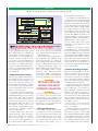
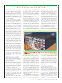
F E A T U R E
M U L T I L A Y E R
S W I T C H
D E S I G N
When Network Design
Meets Chaos Theory
With some careful forethought, the design of feature-laden multilayer
switches doesn’t have to be an exercise in chaos management.
By Michael Orr
s designers know all too well,
development of stable, fullfeatured networking products is becoming increasingly
difficult, because of the alarming pace at
which the complexity of these devices is
growing. This “complexity explosion” is
a result of ever-expanding standards, protocols and applications, used to address
the evolving functions like quality-ofservice, virtual local-area networks
(VLANs), virtual private networks and
policy enforcement that networks are
being asked to deliver. All of those
changes greatly affect the code that runs
network devices, which must constantly
be updated with the latest and greatest
IEEE or IETF standard—even as it is
being ported to the next generation of
switching silicon.
Given that situation, it is not surprising
that the specifications of these multilayer switches typically comprise a long,
growing list of features and functions that
have to be implemented, greatly increasing the time spent on feature implementation, integration and verification.
To meet this growing challenge,
implementation teams typically adopt a
modular approach, where each feature or
group of features is treated as a separate
subproject (see Fig. 1), and is integrated
into a whole in the final stages of development. This time-honored method
allows several tracks to be worked on in
parallel, and allows some (if not all) of the
A
required modules to be acquired—from
either open-source projects like Linux or
commercial vendors. This mix-andmatch methodology fits with the view of
the product as a collection of features.
Unfortunately, that approach misses
the system-level implications, which
have a greater impact on device functionality and integrity than any particular feature. This article will explain some of the
system-level aspects that require special
attention when multilayer switches are
designed and implemented.
There are many aspects to a multilayer
switch that are not related to any particular feature, and many aspects that should
be associated with all features. These will
typically be infrastructure facilities that
should be designed separately, before
any feature is implemented, and should
form a coherent framework that will host
all features, including future functionality. While a complete discussion of those
aspects is beyond the scope of this article,
some examples may illustrate the point.
Resource usage (RAM, interrupts, semaphores, flash, UART, etc.): Every device has
a limited set of resources that is shared by
all subsystems and modules. Allocation of
those must be planned centrally, with
special attention given to extreme cases.
For example, how much RAM will a
table occupy? What will happen if all
4,096 VLANs are active? In some cases,
the way resources are handled may be
significant: Are all interrupts disabled, or
just the lower-priority ones relative to the
module currently running? Is flash memory written sector by sector or file by file?
Resource arbitration must be part of a
systemwide design and cannot be done
on a per-module basis (especially for
imported code), where each source may
have a different set of assumptions about
available resources and their usage.
User interfaces (CLI/WEB/SNMP-based
GUI/Telnet): Almost every feature has
attributes that are, and sometimes must
www.CommsDesign.com FEBRUARY 2003 COMMUNICATION SYSTEMS DESIGN 25
F E A T U R E
M U L T I L A Y E R
be, user-configurable. Users expect to be
able to assign parameters, set limits and
view information through a single, uniform interface, even if underlying features have nothing to do with one another and can be separately implemented.
Even when several ways of achieving the
same purpose are available, all interfaces
are expected to be synchronized and provide the same functionality. Clearly, this
is not something that can be done on a
per-module basis.
■ Implementation choices
During design, difficult choices must be
made about how to use the resources of
the powerful switching ASICs at the
unit’s heart. Trade-offs abound. An
implementation method that is suitable
for one feature may make implementation of some unrelated feature more complicated or even impossible.
For example, typical switching silicon
is composed of packet processors with
multi-Gigabit Ethernet ports and “fabric
adapter” chips, which interconnect the
processor into larger systems—assisted
by such system components as memory,
flash and CPU. While the chips are an
engineering feat—able to carry out complex operations on passing frames at wire
speed—they are essentially a collection
of empty decision tables.
To make matters worse, the various
decision tables have subtle interdependencies such as “If table X is used, then
table Y can’t be used,” or “must be
used”. It is up to the implementer to
choose which decision tables are appro-
S W I T C H
D E S I G N
priate and in what way they should be
used, as well as ensure that this is done in
a consistent manner.
There is also an inherent gap between
the specification and definition of the
desired functionality (as defined by
Internet Engineering Task Force RFCs)
and the available chip mechanisms used
to implement them. For instance, the
IETF DiffServ standard, which comprises several RFCs, defines “per-hop
behaviors” and a Management Information Base (MIB) control language
used to express the desired configuration.
The chip typically has none of that. In-
Difficult choices must be made
about how to use the powerful
switching ASICs at the unit’s heart.
stead, it provides general classifiers, various counters, queues and queue-scheduling algorithms —none of which is even
hinted at in the IETF standard. It is up to
the implementer to use chip facilities to
implement or at least approximate the
desired high-level definition.
■ Internal interfaces
Many modules feature internal interfaces that tie them into common infrastructure elements. If the modules originate from different sources or are implemented independently, those interfaces must be defined in advance, to suit
all features—with thought given to
26 COMMUNICATION SYSTEMS DESIGN FEBRUARY 2003 www.CommsDesign.com
future requirements and changes.
For example, if several modules generate instructions to be placed into the general Internet Protocol (IP) forwarding
table, the routing table must be designed
to store data for all cases. It must also synchronize and coordinate possibly conflicting updates arriving in random order
from multiple sources. Now add to that
some facility to account for future routing
protocols like BGP4 and IS-IS to be
added or the ability to handle equal-cost,
multipath forwarding, and forwarding of
Multicast traffic, and you begin to see
why the routing table and its update
mechanism can’t be designed on a permodule basis.
A similar case can easily be made for
the SNMP interface. As virtually all data
communication devices are expected to
implement SNMP and a large collection
of standard and private MIBs—databases
that describe device status in minute
detail—all features must be represented,
and may manipulate those databases in a
variety of ways. If each module has its
own idea of how this should be handled,
chaos is sure to follow.
■ Future proofing designs
While it is certainly possible to solve all of
the issues mentioned above in an ad hoc
manner and create a device from modules built or acquired from multiple
sources, the result is typically “quick and
dirty,” and makes subsequent changes
and additions harder and harder.
A systematic design can accommodate
inevitable future additions and changes
more readily than a sum-of-parts approach. While it’s certainly not the only
solution on the market that employs a
systematic approach, the OpENS software architecture (see Fig. 2) clearly illustrates a few tricks of the trade that can be
employed to keep a product from becoming “brittle” as it ages.
From experience, we’ve learned that
some items that can be expected to
change are as follows:
Switch ASICs: Whether it’s a slight revision to the currently used chip set or a
whole new generation of switch ASIC,
the new silicon will typically have different capabilities that must be accounted
for in software. Segmenting the software
into a VLSI-dependent module (see Fig.
2 again) addresses part of the challenge,
F E A T U R E
M U L T I L A Y E R
but other issues remain. For example,
even some of the more subtle changes,
like per-port instead of systemwide
scheduling settings, may represent major
operational differences. Also, some might
add the ability to handle MPLS frames as
well as IP. How much of the code will
have to be rewritten?
Service configurations: If a product is
successful, it is certain that similar-butdifferent configurations will be required—more ports, chassis and/or stackable versions of standalone switches—
and standalone versions of stackable
ones. What will be required to implement those variations?
Man-machine interface (MMI): Changing
user requirements mean that new control
elements need to be added to the system,
and new information may have to be collected and displayed. This should be
taken into account, so that it will not be
necessary to go over each and every feature and modify it separately. For example, suppose the CLI syntax and or
semantics need to be modified—how
extensive will the effect be? Suppose the
user adds remote authentication to the
usual local user name/password database.
Will every feature have to be modified?
Even with this small sampling of
issues, it’s apparent that you can’t implement functions and features piecemeal
without inviting disaster. Remember,
before the first feature is implemented, a
good deal of systems-level design is
required to create a consistent framework
to accommodate it. But is this enough?
Of course not!
■ When features collide
Now we will see how features that seem
to work separately interact in surprising
ways when combined.
An important point to note is that
while most of these surprises can, in theory, be foreseen, they are typically discovered the hard way, no matter how
knowledgeable the design team may be.
So, experience counts for a lot.
A comprehensive “What to watch for”
list cannot be provided here, but the
examples cited below are instructive. So
let’s look at some examples along the
general theme of chip/hardware dependencies and side effects.
Scheduling methods: Typically, switching
chips contain several prioritized queues
S W I T C H
D E S I G N
for outgoing traffic on each port for different classes of service. However, after
assigning frames to the appropriate
queue (an issue unto itself, as explained
below), we must still determine which
scheduling method to use.
Do we send all traffic from the highestpriority queue first, then move on to the
next queue, and thus use the so-called
“strict-priority” scheduling, or do we use
“weighted-round-robin” scheduling that
ensures that at least some traffic from
each queue is passed along, with the
amount determined according to some
desired proportion? Different chips may
have not only a different number of
queues with different scheduling meth-
capability to adapt to a straight or crosswired cable, is also taken for granted.
Now combine this with the facility to create trunks—groups of ports behaving as a
single logical entity. The IEEE 802.3ad
port-trunking standard requires that all
ports in a trunk have the same speed, and
be full-duplex. A logical implementation
of that feature will turn off autonegotiation or force the user to turn it off, to
ensure trunk member ports stay at the
common, correct setting. However, in
many—and perhaps most—physical layers, Auto-MDI/X is linked to autonegotiation and will be turned off anyway.
This means that if the cable was
“wrongly” wired, and Auto-MDI allowed
ods, but also may have either a per-port or
a single, systemwide scheduling policy.
This information is typically considered
very obscure, and is frequently not even
documented in the regular user manual.
Now imagine an implementation of
DiffServ, trying to implement “expedited forwarding” per-hop-behavior on
some port. For technical reasons, this
requires the use of strict-priority scheduling. If the scheduling method is systemwide, this will affect all ports in the
system and will cause any other bandwidth assignment feature that assumes
round-robin scheduling to fail (and, of
course, vice versa).
Auto MDI/MDIX and autonegotiation:
Autonegotiation of port speed and duplex
status is now standard. Auto MDI/X, the
it to be used so far, traffic will stop on that
port when Auto-MDI is turned off—
even though it is seemingly unrelated to
the trunking feature. Note, too, that an
exchange of cables may not point to the
problem, as the cable may seem to work
just fine on another port if Auto-MDI is
active there.
■ Interlayer relations
Class-of-service (CoS) is a term used to
describe differential handling of packets
undergoing Layer 2 switching, based on
frame content. Quality-of-service (QoS)
is a term used to describe differential
handling of packets undergoing Layer 3
forwarding. In certain cases, separate
hardware mechanisms may be used to
classify Layer 2 and Layer 3 traffic. While
www.CommsDesign.com FEBRUARY 2003 COMMUNICATION SYSTEMS DESIGN 27
F E A T U R E
M U L T I L A Y E R
the classification of packets in Layer 2
(for CoS) and Layer 3 (for QoS) may be
based on various parts of frame/packet
content, and at times on a higher-level
value, like the TCP port number, it is
important to realize that these processes
are completely independent. In general,
a packet is either switched or routed, but
not both. Note though, that as the actual
switching silicon only has one set of
queues per output port, the result is that
those two processes independently fill
the same queues and may interfere with
each other’s decisions.
In one particular case, Layer 2 and
Layer 3 forwarders were designed to
reserve 80 percent of the device’s link
capacity for their “top-priority” traffic. As
both forwarders filled the same “physical” queue, obviously, neither achieved
its goal. For both CoS and QoS mechanisms to effectively coexist within the
same box, a full understanding of the two
mechanisms and close attention to details
of their integration, in accordance with
operator requirements, were required.
■ Stacking
The revival of interest in stacking adds a
new dimension of complexity, with many
subtle side effects. Out of fashion for several years, stacking products are back in
favor because they allow a group of inexpensive “pizza box” switches to be aggregated and to behave as a single high-density device (see Fig. 3). Unfortunately,
many of the system-level effects of stacking are complex.
Consider a stack consisting of a collection of similar but not identical units such
as devices of different hardware versions
or with different port counts. The user
expects to deal with the stack as a single
logical entity but in some cases, the system must deal with the differences. For
example, let’s say a 48-port unit in the
middle of the stack is replaced with a 24port unit. Will ports be renumbered?
What will happen to the careful per-port
configurations that the user has defined?
What will happen if the units are
switched again?
■ Logical ‘gotchas’
VLAN suspension: As our experience
shows, some seemingly easy, logical
issues may develop into major headaches. For example, one customer want-
S W I T C H
D E S I G N
ed to have a facility for suspending and
re-activating VLANs. However, when
the VLAN is reactivated and all its stored
attributes are restored, is it safe? If any
switch or port settings changed in the
interim, reactivating the VLAN could
result in unexpected side effects. For
example, a port that was suspended as
part of a single VLAN, using 100 percent
untagged traffic, may “reawaken” as a
member of several VLANs or a trunk
Reactivating a suspended VLAN
can have some unexpected side
effects if a port setting is changed.
using tagged frames, yielding some highly unexpected consequences.
SNMP/CLI/Web management clashes: A
potential problem arises if the user is
allowed to configure the device using the
Web, CLI and SNMP interfaces but, as is
common, expects to access configuration
files as a collection of CLI commands.
Care must be taken to ensure that the
actions taken are reported via both the
Web and SNMP-over-CLI mechanisms.
If, however, each of those interfaces is
built separately, it’s likely that some messages will not reach both interfaces. In
particular, SNMP, having finer resolution,
can typically generate configurations that
can’t be properly represented by either
CLI or Web-based Interfaces.
■ Implementation choices
IGMP snooping. Internet Group Management Protocol snooping is a feature of
Layer 2 switches that improves support
for Layer 2 multicasts. When an L2 multicast frame arrives, it is seen by the L2
switch as a broadcast and a copy is sent to
all “relevant” ports. The question is,
which ports are relevant?
Rather than perform pure L2-forwarding (transparent switching) and send a
copy of broadcast frames to all ports in
the VLAN, the switch can “snoop”
IGMP frames exchanged between end
stations and some upstream router. This
helps the switch decide which ports in
the VLAN contain an end station that
actually wants copies of the multicast
traffic, and which ports don’t. Using this
knowledge, the switch can significantly
28 COMMUNICATION SYSTEMS DESIGN FEBRUARY 2003 www.CommsDesign.com
reduce multicast traffic to ports that don’t
necessarily need it.
This works fine in theory, but things
get a bit more complicated in actual
implementation. For some chips, it may
seem that IGMP-like functionality may
be efficiently implemented using a “multicast ID/port list” table. In some cases,
however, the chip in question does not
possess such a table. Alternatively, we can
decide to “invent” a new VLAN, assign
only relevant ports to it and direct that
incoming multicast frame to that “new”
VLAN, and all will be well—or will it?
This now creates ports on which two or
more VLANs are active: user-assigned
VLANs and the newly “invented” multicast VLANs. Problems arise as ports with
more than one active VLAN must decide
if and how to tag incoming and outgoing
frames. While the second VLAN table
permits IGMP functionality, it pretty
much negates “ingress filtering” security
between ports, as they are now assigned
to the same VLAN, opening them up to
each other.
Obviously, designing complex networking products involves wrestling with
the forces of chaos. If you expect to win,
you must adopt a systematic approach.
This means making sure that all individual elements have uniform interfaces
with the overall system. If the expertise
and resources are available, it is possible
to assemble a stable, full-featured system
from protocol stacks and other separate
intellectual property, but it’s often most
efficient to buy a fully integrated system
and customize it to your needs. Finally,
rigorous testing should be used throughout development to uncover the unexpected interactions that will inevitably
arise from a project of this kind. ■
For more on metro access, see:
“Design Considerations for Edge
Routers: Parts 1 and 2”; www.commsdesign.com/story/OEG20020508S004
“Adding VT1.5 Switching to Sonet/
SDH Platforms”; www.commsdesign.com/
OEG20021213S005
Michael Orr ([email protected]) is the vice president of technology and product management at
Radlan Inc. He has a bachelor’s of science
degree in computer science from Technion (Israel
Institute of Technology) in Haifa, Israel.