1
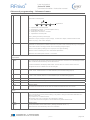
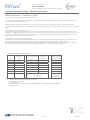
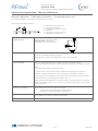
RFnivo
®
1
Level limit switch
Series RF 3000
Technical Information / Instruction manual
Table of contents
2
Page
Safety notes / Technical supportG2
3
IntroductionG3
ApplicationsG4
Technical data:
DimensionsG5
4
Electrical dataG9
Mechanical dataG10
Operating conditionsG11
5
Transport and StorageG12
ApprovalsG13
OptionsG13
6
MountingG14
Electrical installationG20
QickstartG22
7
Advanced prorammingG29
Probe modifications
G35
Assembly - Remote version / FM, FMc Control Drawing
G36
TroubleshootingG37
8
MaintenanceG39
Notes for use in Hazardous Locations
G41
DisposalG43
9
10
Subject to technical change.
We assume no liability for typing errors.
All dimensions in mm (inch).
Different variations than specified are possible.
Please contact our technical consultants.
11
12
RF 3000
gi241014
page G 1
1
RFnivo
Level limit switch
Series RF 3000
Technical Information / Instruction manual
®
Safety notes / Technical support
2
Notes
•
•
Installation, maintenance and commissioning may be accomplished only by qualified technical personnel.
The product must be used only in the manner outlined in this instruction manual.
3
Special attention must be paid to warnings and notes as follows:
WARNING
4
Relates to a caution symbol on the product: A failure to observe the necessary
precautions can result in death, serious injury and/or considerable material damage.
WARNING
5
Relates to a caution symbol on the product: Risk of electric shock
WARNING
6
A failure to observe the necessary precautions can result in death, serious injury
and/or considerable material damage.
This symbol is used, when there is no corresponding caution symbol on the product.
7
8
CAUTION
A failure to observe the necessary precautions can result in considerable material
damage.
Safety symbols
In manual and on
product
Description
CAUTION: refer to accompanying documents (manual) for details.
9
Earth (ground) Terminal
Protective Conductor Terminal
10
Technical support
Please contact your local supplier (for address see www.uwt.de). Otherwise you can contact:
11
UWT GmbH
Tel.: 0049 (0)831 57123-0
Westendstr. 5
Fax: 0049 (0)831 76879
D-87488 Betzigau
[email protected]
www.uwt.de
12
page G 2
gi241014
RF 3000
RFnivo
®
1
Level limit switch
Series RF 3000
Technical Information / Instruction manual
Introduction
2
Applications
Function
The device is used for level monitoring in all types of containers and silos.
The unit detects the capacitance between the probe and
the container wall.
It can be used with all powdery and granulated bulk materials,
slurry and liquids.
The performance allows to use the unit in a wide range of
even difficult applications combined with simple handling:
The units can be delivered with Ex-approvals for use in Dust
and Gas Hazardous Areas.
• Active shield technology
The powerful active shield technology allows to ignore
material build up on the probe. Even the influence
of conductive build up on the probe is electronically
compensated and thus ignored. This allows to measure
with high sensitivity in combination with material build up.
A selection of fields of application:
•
Building materials industry
lime, moulding sand, etc.
•
Food industry
sugar, flour, salt, etc.
•
Plastics industry
plastics granules etc.
•
Timber industry
chipped wood
• Chemical industry
pigments
•
Mechanical engineering
The RFnivo is normally screwed into the lateral container wall
at a position, where the material shall be measured.
The device can also be mounted from the top of the container.
In this case an extension piece is used to mount the probe
level with the height to be measured.
• Self diagnostics
The unit is able to check the internal electronic for proper
functionality. This can be done by setting a frequent auto
test or by pressing a manual test button.
• Auto calibration
The unit will auto calibrate to uncovered state after first
time power up.
3
4
5
It allows to set for auto recalibration to uncovered state.
This is useful in case of a covered probe during power up.
An auto recalibration is done when the probe becomes
uncovered.
• Manual recalibration to uncovered state can be done by
simply pressing a push button.
6
• Full manual calibration can be selected as well.
The sensitivity is preselected to work in most applications
and can be changed if required.
7
The length of the probe can be up to 2.5m (98.4”) with rod
extension or 20m (787") with rope extension.
The use of a sliding sleeve is recommended so that the switch
point can be changed continuously during operation of the
device.
8
9
10
11
12
RF 3000
gi241014
page G 3
1
RFnivo
®
Level limit switch
Series RF 3000
Technical Information / Instruction manual
Applications
2
3
4
5
6
7
8
9
10
11
RF 3100
RF 3200
RF 3300
A
Inactive lenght to reach distance from silo wall
•
•
•
B
Inactive lenght due to long mounting nozzle
•
•
•
C
Full detector with short lengh
•
•
•
D
Demand detector with short lengh, observe max. load
•
•
•
E
Empty detector with short lenght, observe max. load
•
•
•
F
Application in down pipe, observe max. load
•
•
•
G
Inactive length to bring active probe to required level
•
•
•
H
Inactive length and sliding sleeve for adjustable height
•
•
I
Full detector, rope version
•
•
•
J
Empty detector, rope version, observe max. load
•
•
•
K
Inactive lenght due to long mounting nozzle
•
•
•
12
page G 4
gi241014
RF 3000
RFnivo
1
Level limit switch
Series RF 3000
Technical Information / Instruction manual
®
Technical data - Dimensions
2
Housing versions
Aluminium
Plastics PA6
Standard
3
4
de
Explosionproof with
increased safety
terminal box
5
Aluminium
6
d
Flameproof /
explosionproof
7
Aluminium
8
Remote version
9
electronics
inside
no electronics
inside
aluminium
Remote version exemplified with RF 3100
Spezial triaxial cable
max. length: 20m (65ft)
min. bending radius: 50mm (2")
10
Angle bracket
11
Remote cable
12
RF 3000
gi241014
page G 5
1
RFnivo
Level limit switch
Series RF 3000
Technical Information / Instruction manual
®
Technical data - Dimensions
2
Probes
RF 3100 Standard version
Rod version
Shortest length
3
Rod version
Inactive extension
Rope version
Shortest length
Rope version
Inactive extension
4
5
6
7
8
* Active shield
With EHEDG certificate the length "L" is
increased by 9mm (0.35")
9
Process connections:
Thread
G 3/4"
NPT 3/4"
10
Thread
(except 3/4")
Flange
Triclamp
11
12
page G 6
gi241014
RF 3000
RFnivo
1
Level limit switch
Series RF 3000
Technical Information / Instruction manual
®
Technical data - Dimensions
2
RF 3200 Heavy Duty version
Rod version
Shortest length
Rod version
Inactive extension
Rope version
Shortest length
Rope version
Inactive extension
3
4
5
6
7
8
* Active shield
9
Process connections:
Thread
Flange
10
11
12
RF 3000
gi241014
page G 7
1
RFnivo
Level limit switch
Series RF 3000
Technical Information / Instruction manual
®
Technical data - Dimensions
2
RF 3300 High temperature version
Rod version
Shortest length
3
Rod version
Inactive extension
Rope version
Shortest length
Rope version
Inactive extension
4
5
6
7
8
9
* Active shield
10
Process connections:
Thread
11
Flange
12
page G 8
gi241014
RF 3000
RFnivo
1
Level limit switch
Series RF 3000
Technical Information / Instruction manual
®
Technical data - Electrical data
2
Electrical data
Connection terminals
0.14 - 2.5mm2 (AWG 26-14)
Cable entry
M20 x 1.5 screwed cable gland
NPT 1/2“ conduit connection
NPT 3/4” conduit connection
3
Clamping range (diameter) of the factory provided cable glands:
M20 x 1.5: 6 .. 12mm (0.24 .. 0.47"")
Signal delay
Sensor uncovered -> covered or covered -> uncovered or covered <-> uncovered:
adjustable ca. 0.5 to 60 sec
Safety operation
(FSL,FSH)
Operation frequency
Switchable for minimum or maximum safety
Overvoltage category
II
Pollution degree
2 (inside housing)
4
ca. 100kHz
Electronics
Universal voltage
Relay DPDT
Power supply
21 .. 230V 50-60Hz or DC ±10%*
*incl. ±10% of EN 61010
Max. ripple of power
supply
Installed load
7 Vss at DC sypply
5
6
max. 1.5VA or 1.5W
7
Signal output
Floating relay DPDT
AC max. 250V, 8A non inductive
DC max. 30V, 5A non inductive
Display
4 digit LCD
Display of actual measured capacitance, signal
output state and self diagnostics
Min. operating temperature: -30°C (-22°F)
Indicating light
Status by 3 colour built-in LED (according to NE44):
Power on, signal output, failure /maintenance
Data storage
Nonvolatile EPROM for Menu settings and calibration data
Isolation
Power supply to signal output: 2225Vrms
Signal output to signal output: 2225Vrms
Protection class
I
8
9
10
11
12
RF 3000
gi241014
page G 9
1
RFnivo
Level limit switch
Series RF 3000
Technical Information / Instruction manual
®
Technical data - Mechanical Data
2
Mechanical data
Housing
Aluminium, powder coated RAL 5010 gentian blue
Optional: Plastics PA6 reinforced
Seal between housig and lid: NBR
Seal between housing and process connection: NBR
Nameplate: polyester film
Degree of protection
IP 67 (EN 60529), NEMA Type 4X
Process connection
/ probes
RF 3100:
Material: Stainless steel 1.4301 (304)/1.4305 (303) or 1.4404 (316L)/1.4401(316) for rope
Probe isolation PPS reinforced
Coating of probe/rope (optional) PFA
Thread: G 3/4", 1", 1¼", 1½“ DIN 228, M30x1.5, M32x1.5, NPT 3/4", 1", 1¼”, 1½“ tapered ANSI B 1.20.1
Triclamp: 1" (DN25), 1½" (DN40), 2" (DN 50) ISO 2852
RF 3200:
Material: Stainless steel 1.4301 (304)/1.4305 (303) or 1.4404 (316L)/1.4401(316) for rope
Probe isolation PPS reinforced
Thread: G 1¼, 1½“ DIN 228, NPT 1¼”, 1½“ tapered ANSI B 1.20.1
RF 3300:
Material: Stainless steel 1.4301 (304)/1.4305 (303) or 1.4404 (316L)/1.4401(316) for rope
Probe isolation ceramic
Thread: G 1¼, 1½“ DIN 228, NPT 1¼”, 1½“ tapered ANSI B 1.20.1
3
4
5
6
Flanges according to selection 1.4541 (321) or 1.4404 (316L)
All material food grade
Sound level
7
max. 40dBA
Overall weight
(ca.)
Standard
housing
dehousing
dhousing
3.0 kg
(6.6 lbs)
3.6 kg
(8.0 lbs)
2.8 kg
(6.2 lbs)
2.7 kg
(6.0 lbs)
3.3 kg
(7.3 lbs)
3.8 kg
(8.4 lbs)
Active probe length:
L1**
+0.62 kg/m
(1.37 lbs/39.3“)
+0.06 kg/m
(0.13 lbs/39.3“)
4.1 kg
(9.0 lbs)
+3.0 kg/m
(6.61 lbs/39.3“)
+3.26 kg/m
(7.19 lbs/39.3“)
4.0 kg
(8.8 lbs)
3.6 kg
(8.0 lbs)
4.8 kg
(11 lbs)
5.0 kg
(11 lbs)
4.6 kg
(10 lbs)
5.8 kg
(13 lbs)
5.3 kg
(12 lbs)
4.9 kg
(11 lbs)
6.1 kg
(13 lbs)
+0.26 kg/m
(0.57 lbs/39.3“)
+3.0 kg/m
(6.61 lbs/39.3“)
+0.26 kg/m
(0.57 lbs/39.3“)
+3.26 kg/m
(7.19 lbs/39.3“)
+3.26 kg/m
(7.19 lbs/39.3“)
+3.26 kg/m
(7.19 lbs/39.3“)
Basic weight*
8
9
RF 3100
rod version
RF 3100
rope version
1.7 kg
(3.7 lbs)
2.3 kg
(5.1 lbs)
RF 3200
rod version
RF 3200
rope version
RF 3300
rod version
RF 3300
rope version
Inactive length:
L2**
+1.2 kg/m
(2.65 lbs/39.3“)
+1.2 kg/m
(2.65 lbs/39.3“)
Total weight = Basic weight + active probe length L1 + inactive length L2
All weights with 1 1/4" NPT process connection and without flanges
* Rode version with shortest length L1=100mm (3.9"), rope version without rope
**Refer to dimension drawings on page G6-G8
10
11
12
page G 10
gi241014
RF 3000
RFnivo
1
Level limit switch
Series RF 3000
Technical Information / Instruction manual
®
Technical data - Operating conditions
2
Operating conditions
Ambient temp. (housing)
-40°C.. +70°C (-40 .. +158°F)
Process temperature
RF 3100 / 3200:
RF 3300:
-40°C.. +240°C (-40 .. +464°F)
-40°C.. +500°C (-40 .. +932°F), versions with Ex-approvals: +445°C (+833°F)
3
.
4
For versions with Ex-approvals: see remarks on page G42.
5
Ventilation
Ventilation is not required
Max. range / max
sensitivity
3 .. 100pF / 0.5pF
3 .. 400pF / 2pF
Spark protection
Robust build in protection against static discharge of the bulk material.
Features of bulk material
Min. DK depending on selected probe length L1 and probe diameter.
See tables on page G25 and G32.
6
Max. mechanical load
Max. load with
rod version
7
All ratings for 40°C (104°F)
RF 3100 Rod version:
Rope version:
A: 125 Nm 4 kN tensile load
RF 3200 Rod version:
Rope version:
A: 525 Nm B: 90 Nm
40 kN tensile load
RF 3300 Rod version:
Rope version:
A: 525 Nm B: 20 Nm 10 kN tensile load
8
B: 20 Nm
9
Max. process pressure
10
The max. process pressure may be reduced with use of flanges. Observe flange standards for
pressure rating and pressure derating with higher temperature.
11
For versions with Ex-approvals: Further see remarks on page G41.
12
RF 3000
gi241014
page G 11
1
RFnivo
Level limit switch
Series RF 3000
Technical Information / Instruction manual
®
Technical data - Operating conditions
2
Vibration
1.5 (m/s2) 2 /Hz according to EN 60068-2-64
Relative Humidity
0-100%, suitable for outdoor use
Altitude
max. 2.000m (6.562ft)
3
Expected product lifetime
Following parameters have a negative influence on the expected product lifetime:
High ambient- and process temperature, corrosive environment, high vibration, high flow rate of
abrassive bulk material passing the sensor element.
4
Transport and Storage
Transport
Observe the instructions as stated on the transport packaging, otherwise the products may get
damaged.
Transport temperature: -40 .. +80 °C (-40 .. +176 °F)
Transport humidity: 20 .. 85 %
5
Transport incoming inspections must be caried out to check for possible transport damage.
Storage
Products must be stored at a dry and clean place. They must be protected from influence of corrosive
environment, vibration and exposure to direct sunlight.
Storage temperature: -40 .. +80 °C (-40 .. +176 °F)
Storage humidity: 20 .. 85 %
6
7
8
9
10
11
12
page G 12
gi241014
RF 3000
RFnivo
1
Level limit switch
Series RF 3000
Technical Information / Instruction manual
®
Approvals / Options
2
Approvals
General Purpose *
(Ordinary Locations)
CE
FM / FMc
EN 61010-1
Hazardous
Locations *
ATEX
Dust explosion
Protection by enclosure
II 1/2D Ex ia/tb IIIC T! Da/Db
Gas explosion
Flameproof
Flameproof / increased safety
II 2G
II 2G
Dust explosion
Gas explosion
Protection by enclosure
Ex ia/tb IIIC T! Da/Db
Flameproof
Flameproof / increased safety
Ex d ia IIC T! Gb
Ex de ia IIC T! Gb
Dust explosion Protection by enclosure
Cl. II, III Div.1 Gr. E,F,G
Gas explosion
Flameproof
XP-IS Cl. I Div.1 Gr. A-D
Cl. I Zone 1 Gr. IIB+H2
IEC-Ex
FM / FMc
3
Ex d ia IIC T! Gb
Ex de ia IIC T! Gb
4
5
Detailed allocation of types and electronic modules to approvals: see selection list.
EMC
EN 61326 -A1
Hygiene *
EHEDG (Type ED)
Food grade material
According to directive 1935/2004/EC
Pressure Equipment
Directive (97/23/EC)
The units are not subject to this directive, because they are classified as „pressure-keeping equipment“ and
do not have a pressurized housing (see Art.1, clause 2.1.4).
The units are designed and manufactured in accordance to the Pressure Equipment Directive.
The unit is NOT intended for use as a “equipment part with safety function (Art.1, clause 2.1.3).
If the units should be used as „equipment part with safety function, please contact the manufacturer.
* depending on selected version in the selection list.
6
7
8
Options
Various options are available, see pricelist for more details:
Remote version
• Probe and electronic housing separated (cable length up to 20m (65ft))
Electronics
• Preselected sensitivity (factory setting of switching sensitivity )
Probes
• Coating rod version (active probe or complete probe)
• Coating rope version (rope)
• Extension kits (rigid or flexible rod extension, rope extension)
Mounting
• Sliding sleeve (flexible height adjustment of the probe)
• EHEDG approval (Type ED)
• Mounting sets: Screws, washers, sealings for fixing the unit on a flange.
Housing
•
•
•
•
•
9
10
Housing material plastics PA6
Weather protection cover (PE, weathering and temperature stable)
Cable entry (metric or NPT with different size)
Signal lamp (indiation of signal output state from outside)
Plugs (valve connector, M12 plug, Harting)
11
12
RF 3000
gi241014
page G 13
1
RFnivo
®
Level limit switch
Series RF 3000
Technical Information / Instruction manual
Mounting
2
General Safety Instructions
Process pressure
Improper installation may result in loss of process pressure.
Seal the process thread with Teflon tape in case of process pressure
A plastic sealing must be used to tighten the flange.
Fastening of the
threaded process
connection
Mounting torque for the thread may not exceed 80Nm. Use a fitting open-end wrench. Do not fasten by
turning the housing.
Sliding sleeve: Tighten both straining screws M8 with 20 Nm to obtain resistance against pressure.
Direction of the cable
glands
When the unit is mounted from the side, ensure, that the cable glands faces downwards and are closed
to avoid water penetration into the housing. The housing can be rotated against the process connection
after mounting.
Chemical resistance
against the medium
Materials of construction are chosen based on their chemical compatibility (or inertness) for general
purposes. For exposure to specific environments, check with chemical compatibility charts before
installing.
Temperature range
The range of the ambient and process temperature of the device must be observed.
Mechanical load
The rated values must not be exceeded.
EHEDG / Food grade
material
The materials are available for the use under normal and predictable applications (according to
directive 1935/2004 Art.3). Other conditions can influence the safety.
3
4
5
6
7
8
Additional Safety Instructions for Hazardous Locations
Installation regulations
For devices to use in hazardous locations the respectively valid installation regulations must be
observed.
Sparks
The installation has to be done in a way mechanical friction or impact can not cause sparks between
the aluminium enclosure and steel.
Weather protection
cover
The weather protection cover is approved for Zone 2, 22 and Div.2
9
10
11
12
page G 14
gi241014
RF 3000
RFnivo
®
1
Level limit switch
Series RF 3000
Technical Information / Instruction manual
Mounting
2
EHEDG Approval
Seal the thread with teflon tape against process pressure.
Metal-metal sealing:
• The support muß be plane and without any gap. No teflon tape (or similar) is allowed to be in between.
• Fixing torque 100Nm
3
The quality of the welding with the container wall must be according to the respective regulations
(e.g. gaps, transitions, surface finish).
4
Total length L + 9mm (0.35")
Flush welding
socket
5
metal-metal
sealing
seal thread with
teflon tape
6
welding with
container wall
7
Dimension of flush welding socket (for optional on site manufacturing):
Surfaces in contact with
process Ra <=0.8um
Section B
Section A
8
Dimensions in mm
9
* suggested values
(in brackets values to be
adhered bindingly)
10
11
12
RF 3000
gi241014
page G 15
1
RFnivo
Level limit switch
Series RF 3000
Technical Information / Instruction manual
®
Mounting
2
Mounting: Rod version
Observe distance to
active probe
Active
probe
Active
probe
3
CORRECT
Horizontal mounting
CORRECT
Oblique mounting
Helps remaining material to fall off
4
Active
probe
5
Active
probe
CORRECT
Long socket.
Use of inactive
length.
6
CORRECT
Extensive material build
up. Use of inactive
length.
7
8
WRONG
Active probe inside
socket.
9
WRONG
Active probe inside
material build up.
WRONG:
Active probe inside intersection between
cylindric and conical part of the silo
(material may stay when silo is empty)
10
11
12
page G 16
gi241014
RF 3000
RFnivo
®
1
Level limit switch
Series RF 3000
Technical Information / Instruction manual
Mounting
2
Observe min. distance between two sensors, to metal
silo wall and to protective angle.
3
4
5
Grounding reference
with non metal silos
The inner or outer PE terminal must be connected to reach a grounding reference.
Further mounting
requirements
• Observe distance to material flow (filling).
• Protective angle recommended depending on mechanical load and abrasion of the material.
Switching point
With proper calibration the signal output switches when the active probe is covered by material.
6
7
8
9
10
11
12
RF 3000
gi241014
page G 17
1
RFnivo
Level limit switch
Series RF 3000
Technical Information / Instruction manual
®
Mounting
2
Mounting: Rope version
Observe distance to
active probe
3
CORRECT
Long socket.
Use of inactive length.
CORRECT
Short socket.
WRONG
Active probe
inside socket.
WRONG:
Active probe inside
intersection between
cylindric and conical part of
the silo (material may stay
when silo is empty)
Active probe
5
Active probe
4
6
Observe min. distance between two sensors and to
metal silo wall.
7
8
9
10
11
Grounding reference
with non metal silos
The inner or outer PE terminal must be connected to reach a grounding reference.
Further mounting
requirements
• Observe distance to material flow (filling).
• Empty detector: Do not mount above the center of the silo outlet due to high traction force.
• Unit must be installed vertical.
12
page G 18
gi241014
RF 3000
RFnivo
1
Level limit switch
Series RF 3000
Technical Information / Instruction manual
®
Electrical installation
2
General Safety Instructions
Handling
In the case of inexpert handling or handling malpractice the electric safety of the device cannot be
guaranteed.
Protective earthing
Before any electrical installation, the terminal inside the housing must be connected to the protective
earth.
Installation regulations
The local regulations or VDE 0100 (Regulations of German Electro technical Engineers) must be
observed.
WIth use of 24V supply voltage, an approved power supply with reinforced insulation to mains is
required.
Fuse
Use a fuse as stated in the connection diagrams.
RCCB protection
In the case of a defect, the distribution voltage must automatically be cut off by a RCCB protection
switch so as to protect the user of the device from indirect contact with dangerous electric tensions.
Power supply switch
A Power-supply-disconnecting switch must be provided and marked near the device.
Wiring diagram
The electrical connections have to be made according to the wiring diagram.
Supply voltage
Compare the supply voltage applied with the specifications given on the electronic and name plate
before switching the device on.
Cable gland / closing
element
The screwed cable gland and closing element must have following specifications:
3
4
5
6
Ingress protection IP67, temperature range from -40°C to +80°C, UL or VDE certified (depending on
the country where the unit is installed), pull relief.
Make sure that the screwed cable gland safely seals the cable and that it is tight (danger of water
intrusion).
Cable glands that are not used have to be locked with a closing element.
7
A strain relief must be provided for the field wiring cables, when the device is installed with the factory
provided cable glands.
Conduit system
In case of using a conduit system (with NPT thread) instead of a cable gland the regulations of the
country where the unit is installed must be observed. The conduit must have a tapered thread either
NPT 1/2“ or NPT 3/4” in accordance with the unit and ANSI B 1.20.1. Not used inlets must be closed
tight with a metal closing element.
8
Field wiring cables
• The diameter has to match to the clamping range of the used cable gland.
• The cross section has to match with the clamping range of the connection terminals and consider
the max. current.
• All field wirings must have insulation suitable for at least 250V AC.
• The temperature rating must be at least 90°C (194°F).
• If higher immunity interferences as specified in the stated EMC standards are present (see chapter
approval), a shielded cable is required, otherwise an unshielded instrumentation cable is satisfactory.
9
Connecting the terminals
Make sure that max. 8mm (0.31“) of the pigtails are bared (danger of contact with live parts).
Guiding the cables in the
terminal box
Cut the field wiring cables to appropriate length to fit properly into the terminal box.
Remote housing
The remote cable must be installed sepatated from power supply lines to avoid immunity
interferences The min. bending radius of 50mm must be observed.
10
11
12
RF 3000
gi241014
page G 19
1
RFnivo
Level limit switch
Series RF 3000
Technical Information / Instruction manual
®
Electrical installation
2
3
4
Relay protection
Provide protection for relay contacts to protect the device against spikes with inductive loads.
Protection against static
charging
The housing of the unit must be grounded in any case to avoid static charging of the unit on
applications with pneumatic conveying and non-metallic containers .
Before opening the lid take care, that the unit is clean and no water or dirt can enter into the housing.
Opening the lid
Additional Safety Instructions for Hazardous Locations
External equipotential
bonding terminal
Connect with
equipotential
bonding of
the plant
5
Field wiring
6
A pull relief must be provided for the field wiring cables, when the device is installed with the factory
provided cable glands.
Field wiring terminals for Fixing torque : 0,5-0,6Nm
“de” housing
Remove wire isolation: 9mm
Cable glands and conduit Installation according to the regulations of the country, where the product is installed.
system for ATEX / IEC-Ex
(Dust and Gas Hazardous
Not used entries have to be closed with blanking elements certified for this purpose.
Locations)
Where available the factory provided parts must be used.
7
A strain relief must be provided for the field wiring cables, when the device is installed with the factory
provided cable glands.
If other than the factory provided parts are used, following must be ensured:
The parts must have an approval adequate to the approval of the level sensor (certificate and type of
protection).
The approved temperature range must be from the min. ambient temperature of the level sensor to the
max. ambient temperature of the level sensor increased by 10 Kelvin.
The parts must be mounted according to the instructions of the supplier.
8
Conduit system
for FM
(Dust and Gas Hazardous
9
10
Locations)
General requirements:
In addition the regulations of the country must be observed. The used flameproof seals and blanking
elements must have an adequate type approval and a temperature range of at least –40°C (-40°F)
to +80°C (176°F). In addition they shall be suitable for the conditions and correctly installed. Where
available the provided original parts of the manufacturer must be used.
Installation of a flameproof enclosure “d” with a conduit system:
In a conduit system single electric conductors are installed in a certified pipe system. This pipe system
is in a flameproof construction as well. The flameproof enclosure “d” and the pipe system needs to be
sealed from each other by a certified flameproof seal. Conduit entries of a flameproof enclosure “d”
shall have installed the flameproof seal within 18 inches from the enclosure wall. Not used entries have
to be closed with adequate blanking elements of a certified flameproof type AEx Cl.1 Div.1 A.
Opening the lid
Units with Dust Explosion approval:
Before opening the lid take care, that no dust deposits or whirlings and no hazardous atmosphere is
present.
Units with flameproof GasExplosion approval (d-housing):
To prevent ignition of hazardous atmospheres, do not remove the lid (cover) while circuits are alive.
11
12
page G 20
gi241014
RF 3000
RFnivo
1
Level limit switch
Series RF 3000
Technical Information / Instruction manual
®
Electrical installation
2
Connection
Standard housing
Connecting
terminals
d-housing
de-housing
Connecting
terminals
Connecting
terminals
3
4
5
Protective
Conductor
Terminal
Protective
Conductor
Terminal
Protective
Conductor
Terminal
6
Universal voltage
Relay DPDT
Power supply:
21 .. 230V 50/60Hz or DC +/-10%
1.5VA or 1.5W
7
Fuse on power supply:
max 10A, 250V, HBC, fast or slow
Signal output:
8
Floating relay DPDT
AC max. 250V, 8A, non inductive
DC max. 30V, 5A, non inductive
Signal output
Fuse on signal output:
max 10A, 250V, HBC, fast or slow
Power supply
9
10
11
12
RF 3000
gi241014
page G 21
1
RFnivo
®
Level limit switch
Series RF 3000
Technical Information / Instruction manual
2
3
4
5
Quickstart
6
7
8
9
10
11
12
page G 22
gi241014
RF 3000
RFnivo
®
1
Level limit switch
Series RF 3000
Technical Information / Instruction manual
Quickstart
2
User interface
3
LEDs:
Green = relay activated
Yellow = relay idle
Red = maintenance (blinking), error (on)
Display
4
Power up calibration at first time operation
5
Behaviour after first time power up (factory setting).
If unit is switched OFF and then again ON, this calibration will NOT be repeated.
1. Ensure material level is well below
the probe.
Ensure that the unit is properly
mounted and the material level is well
below the probe, since the unit
will calibrate to an uncovered probe.
6
2. Power up calibration
After first time power up, the unit will automatically calibrate.
During calibration (ca. 45 seconds) display states "CAL", red LED is blinking.
After calibration display states the actual measured capacitance followed by "u" for
"Signal output states uncovered".
7
If other statements on the display are present, see Trouble shooting, page G37.
3. Checking Quickstart settings
If required to change the factory settings for Fail Safe High/Low, Signal output delay or
Sensitivity, use Quickstart menu (see page G24).
Unit is ready to work
Measurement mode
9
The unit states the actual measured capacitance and the state of the signal output
Display
LED
Explanation
XXX u
XXX c
green/yellow*
Actual measured capacitance in pF.
Actual signal output: states uncovered probe "u" or covered probe "c"
8
Resolution is 0.1pF (<100pF) or 0.5pF (>100pF). If values are >100pF, a dot behind the number means 0.5
pF (e.g. 100. means 100.5pF)
Note: If the actual measured capacitance is higher than electronic can measure (>400pF with sensitivity
setting >=2pF or >100pF with sensitivity setting <=1pF), the unit will state "400c" or "100c". The
measurement is valid, since the actual capacitance is well above the calibrated switchpoint.
Signal output states covered probe "c" in any case.
* Green or yellow depending on FSH/FSL setting, see page G24.
10
11
If other statements on the display are present, see Trouble shooting, page G37.
12
RF 3000
gi241014
page G 23
1
RFnivo
Level limit switch
Series RF 3000
Technical Information / Instruction manual
®
Quickstart
2
Quickstart menu
Note: Red LED is blinking during Menu setting
• When the unit is in Measurement mode, press MENU button for 3 sec to enter in Quickstart menu.
Note: If "Code" is displayed, a Lock Code is required. Set the code number with the arrow buttons and confirm with
the Menu button. Then press again the Menu button for 3 sec to enter in Quickstart menu.
• Press for 3 sec to return to Measurement mode.
• Press for <1 sec to store setted value and jump to next menu item.
3
• Arrow buttons increase / decrease the value to be setted
4
5
6
7
Display
Explanation
Menu item
A. FSH *
FSL
Fail Safe High
Fail Safe Low
Signal output, Fail safe setting
B. ALL *
C-U
U-C
Covered probe <-> Uncovered probe
Covered probe -> Uncovered probe
Uncovered probe -> Covered probe
Signal output , Delay direction
C. 0,5 *
2
5
to 60
seconds
Signal output , Delay time
Adjustable in steps (increment is 5 seconds)
D. 0,5
1
2 **
4
10
15
25
35
pF
Sensitivity
Required capacitance increase between uncovered probe (after
calibration) and switch to output "covered probe".
Change presetted value only if required by the application, see
calibration guide on page G25.
Note: Menu item D is not valid and will not bee shown on the
display, if Manual calibration (Menu item G) is set to ON.
* Factory setting
** Standard Factory setting is 2pF. Optional other setting is present (depending on order)
8
FSH / FSL Setting
9
FSH: Set as full detector. Power failure or line break is stated as "full" signal (protection against overcharging).
FSL: Set as empty detector. Power failure or line break is stated as "empty" signal (protection against dry running).
Setting
10
Signal output
Relay DPDT
LED
yellow
green
yellow
green
power failure
11
uncovered
probe
covered
probe
12
page G 24
gi241014
RF 3000
RFnivo
1
Level limit switch
Series RF 3000
Technical Information / Instruction manual
®
Quickstart
2
Push button calibration - Calibration guide
Push button calibration needs to be done, if "Power up calibration at first time operation" was not sucessful or unit was changed to
another location or a significant change of DK was present after changing of material.
This guideline is applicable for most applications. Some critical applications (e.g. excessive buildup, special mounting) may be
considered different.
A proper selection of the active probe length is necessary in any case to reach a satisfactory change of capacitance between
uncovered and covered probe, see recommendations in the external selection list (pricelist). The table below is based on a proper
active probe length.
• Calibration with uncovered probe only:
This method is most simple and thus recommended to be done if ever possible.
It is applicable for higher DK values which give a higher change of capacitance between uncovered and covered probe. The DK value
of the material is roughly required to be known to be able to set the sensitivity. See external list for dielectric constant (DK) of different
materials.
• Calibration with uncovered and covered probe:
This method is most safe, since it sets the switchpoint in the middle between uncovered and covered probe capacitance. This
ensures the max. switching distance to both uncovered and covered probe capacitance and thus ensures the max. tolerance against
e.g. material buildup. The method is required for lower DK values which give a lower change of capacitance. The DK value of the
material is not required to be known.
DK
Sensitivity
Setting
Calibration
Uncovered and
covered probe
< 1.5
-
-
-
1.5 ... 1.6
-
0.5 pF*
A
1.7 ... 1.9
B
1 pF*
C
2.0 ... 2.9
B
2 pF
C
3.0 ... 4.9
B
4 pF
C
5.0 ... 10
B
10 pF
C
> 10
B
15 pF
Calibration prodedure
see page G26
4
5
6
Push button calibration - Calibration guide
Calibration
Uncovered probe
only
3
7
C
8
Calibration
prodedure
see page G27
A = Required
B = Recommended (most simple calibration method)
C = Possible as an alternative
- = Not applicable
* Not possible with remote version with remote cable length >10m (33ft)
and outdoor installation (temperature drift).
9
10
11
12
RF 3000
gi241014
page G 25
1
RFnivo
Level limit switch
Series RF 3000
Technical Information / Instruction manual
®
Quickstart
2
Push button calibration - Calibration procedure - Uncovered probe only
Explanation of calibration procedure:
3
Capacitance
Capacitance Uncovered probe
Sensitivity
Switchpoint
Capacitance Covered probe
1. Ensure material level is well
below the probe.
Ensure that the unit is properly mounted and the
material level is well below the probe, since the unit
will calibrate to an uncovered probe.
2. Set Sensitivity
Check for the required Sensitivity depending on the material to be measured, use calibration
guide on page G25.
4
5
A
B
C
D
Set the Sensitivity in the Quickstart Menu, item "D", see page G24.
6
3. Press CAL button
for 3 seconds
During calibration the display states "CAL", the red LED is blinking.
Wait until calibration is finished (ca. 10 seconds). Then display states the actual measured
capacitance followed by "u" for "Probe uncovered".
Note: If "Code" is displayed, a Lock Code is required. Set the code number with the arrow
buttons and confirm with the Menu button. Then press again the CAL button for 3sec to start
calibration.
7
If other statements on the display are present, see Troubleshooting, page G37.
Unit is ready to work.
8
9
10
11
12
page G 26
gi241014
RF 3000
RFnivo
1
Level limit switch
Series RF 3000
Technical Information / Instruction manual
®
Quickstart
Push button calibration - Calibration procedure - Uncovered and covered probe
2
Explanation of calibration procedure:
Capacitance
1. Ensure material level is well
below the probe.
2. Press CAL button
for 3 seconds
A
B
C
D
Capacitance Uncovered probe
Sensitivity
Switchpoint
Capacitance Covered probe
3
Ensure that the unit is properly mounted and the
material level is well below the probe, since the unit
will calibrate to an uncovered probe.
4
Display states "CAL", the red LED is blinking.
Wait until calibration is finished (ca. 10 seconds). Then display states the actual measured
capacitance followed by "u" for "Probe uncovered".
5
Note: If "Code" is displayed, a Lock Code is required. Set the code number with the arrow
buttons and confirm with the Menu button. Then press again the CAL button for 3sec to start
calibration.
6
If other statements on the display are present, see Trouble shooting, page G37.
3. Note actual measured
Note the actual measured capacitance as stated in the display for uncovered probe.
capacitance (uncovered probe)
4. Note actual measured
capacitance (covered probe)
For vertical mounting (rope version) the material level shall
cover the probe weight by 10-20cm (4-8").
7
Note the actual measured capacitance as stated in the
display for covered probe.
4. Set Sensitivity
8
Calculate the capacitance difference between uncovered and covered probe.
Set sensitivity as follows (Quickstart Menu item "D"):
Horizontal mounting
Vertical mounting (rope version)
Capacitance
Sensitivity*
difference
uncovered-covered
Capacitance
Sensitivity**
difference
uncovered-covered
0.8 .. 1.5 pF
1.5 .. 3 pF
3 .. 6 pF
6 .. 15 pF
15 .. 23 pF
23 .. 38 pF
38 .. 53 pF
> 53 pF
0.5 .. 1.0 pF
1.0 .. 2 pF
2 .. 4 pF
4 .. 10 pF
10 .. 15 pF
15 .. 25 pF
25 .. 35 pF
> 35 pF
0,5 pF***
1 pF***
2 pF
4 pF
10 pF
15 pF
25 pF
35 pF
9
0.5 pF***
1 pF***
2 pF
4 pF
10 pF
15 pF
25 pF
35 pF
10
* The difference uncovered to covered should be well above the setted sensitivity (ca. >50%).
** The difference uncovered to covered does not need to be above the setted sensitivity, since
with raising material the capacitance will increase and thus lead to a save switching.
*** Not possible with remote version with remote cable length >10m (33ft) and outdoor
installation (temperature drift).
11
Note: If different materials needs to be measured in the same bin without recalibration, the
Sensitivity must be set for the material with the lowest DK.
Unit is ready to work.
12
RF 3000
gi241014
page G 27
1
RFnivo
Level limit switch
Series RF 3000
Technical Information / Instruction manual
®
Quickstart
2
Calibration - general items
Reset to "Power up
calibration at first time
operation"
3
It may be required, that an already calibrated unit shall do a new Power up calibration when the
supply voltage is switched on (e.g. if the unit shall be installed in a different bin or shall be pesetted
and afterwards send to the end user).
To do this, press the CAL button for 3 seconds to initiate a Push button calibration. While the
calibration is running ("CAL" is displayed), switch off the supply voltage. Since the calibration was
startet, but not sucessfully finished, it will automatically start again when power is back.
Note: Only the calibration is affected, the settings in the menus will not change.
4
5
Data storage of last valid
calibration values
If power supply is switched off, the last valid calibration values are stored and are still valid when
power is switched on again.
Manual Function Test (proof test)
General items
The unit allows to test the internal electronics and the external connected signal evaluation.
Test procedure
In Measurement mode:
Start the test by pressing the TEST button for 3 seconds.
6
Note: If "Code" is displayed, a Lock Code is required. Set the code number with the arrow buttons
and confirm with the Menu button. Then press again the TEST button for 3sec to start test procedure.
Test runs for ca. 20 seconds. Display states "TST". Signal output and yellow status LED will change
state for ca. 10 sec and then return to former state (relais on-off-on or off-on-off).
7
If test result is not o.k., the display states "ERR", red LED is on, Relais is set to de-energized.
Electronic is defect and must be changed.
8
9
10
11
12
page G 28
gi241014
RF 3000
RFnivo
®
1
Level limit switch
Series RF 3000
Technical Information / Instruction manual
2
3
4
5
Advanced programming
6
7
8
9
10
11
12
RF 3000
gi241014
page G 29
1
RFnivo
Level limit switch
Series RF 3000
Technical Information / Instruction manual
®
Advanced programming - Advanced menu
2
Advanced menu
Note: Red LED is blinking during Menu setting
• When the unit is in Measurement mode, press MENU button for 10 sec to enter in Advanced menu
(keep pressed, ignore when unit goes after 3 sec to Quickstart Menue and A.FSx is displayed).
Note: If "Code" is displayed, a Lock Code is required. Set the code number with the arrow buttons and confirm with
the Menu button. Then press again the Menu button for 10 sec to enter in Advanced menu.
• Press for 3 sec to return to Measurement mode.
• Press for <1 sec to store setted value and jump to next menu item.
3
• Arrow buttons increase / decrease the value to be setted
4
5
Display
Explanation Menu item
Auto recalibration
F.
OFF *
ON
Auto recalibration to uncovered probe.
If may be required to do comissioning in an already filled silo (covered probe). With covered probe a
proper calibration is not possible. A solution can be to cause the unit to do a auto calibration when
the silo becomes empty (uncovered probe).
6
To do this, set Auto recalibration to "ON" and do a push button calibration with a covered probe
(press the CAL button for 3 seconds).
The unit will recalibrate to uncovered probe automatically after 2 minutes, if the measured
capacitance becomes 50% of the setted sensitivity (Menu item D) lower than the calibrated
capacitance. During calibration "CAL" is displayed.
7
Do not set to "ON" if excessive material build up is present, since this build up may decrease the
measured capacitance and causes a wrong calibration.
Note: Menu item F is not valid and will not bee shown on the display, if Manual calibration (Menu item
G) is set to "ON".
8
Manual calibration
The unit allows Manual calibration similar to conventional potentiometer calibration, but using a comfortable display and menu.
Procedure for Manual calibration see page G32 to G34.
G.
OFF *
ON
H.
LO *
HI
9
10
11
Manual calibration ON/OFF
If set to ON:
- Menu items H-P appear.
- Menu items D (Sensitivity in Quicksart Menu) and F (Auto recalibration) are no more
valid and will be hidden.
- Push button calibration is no more possible (if CAL button is pressed, the display
states G.ON")
Low
High
Sensitivity range
Low sensitivity range allows to detect a capacitance change of >=2pF
High sensitivity range allows to detect a capacitance change of >=0.5pF
See also calibration guide on page G32
Continuation next page
12
page G 30
gi241014
RF 3000
RFnivo
1
Level limit switch
Series RF 3000
Technical Information / Instruction manual
®
Advanced programming - Advanced menu
K.
xxx
pF
2
Switchpoint covered -> uncovered
Explanation of switchpoints:
3
Capacitance
A
C
D
E
F
Capacitance uncovered probe
Switchpoint covered -> uncovered (Menu item K)
Hysteresis (Menu item L)
Switchpoint uncovered -> covered
Capacitance covered probe
4
Factory setting is lowest pF value (3pF).
Resolution is 0.1pF (<100pF) or 0.5pF (>100pF). If values are >100pF, a dot behind the number
means 0.5 pF (e.g. 100. means 100.5pF)
L.
xxx
pF
Hysteresis
Hysteresis can be adjusted if unstable capacitance is present with covered probe (e.g. moving liquid
surface with vertical mounting) to avoid nervous switching of signal output.
5
Minimum value (=factory setting) is 0.5 / 0.2pF (for Low/ High sensitivity) .
Maximum value is limited by the max. measurable capacitance.
6
Resolution see "Switchpoint covered -> uncovered".
Diagnostics
M.
ON *
OFF
Auto Function Test
The unit allows to permanently auto test the internal electronics. The test runs in the background and
does not influence the functionaly of the measurement.
If a failure is detected, the display states "ERR", the red LED is on and the relais is set to deenergized. Electronic is defect and must be changed.
N.
xxx
pF
Actual calibrated Switchpoint covered -> uncovered
If "OR" or UR" is stated, there is no valid calibration (see Troubleshooting page 37)
P.
xxx
pF
Actual calibrated Switchpoint uncovered -> covered
If "OR" or UR" is stated, there is no valid calibration (see Troubleshooting page 37)
Q.
xxx
°C
Min. stored electronics temperature
R.
xxx
°C
Max. stored electronics temperature
S.
xxx
Software version
T.
xxx
Service values
The values are manufacturer internal and not be stated in detail with this user manual
7
8
9
Divers
V.
xxx
Lock code
The Lock code can be set to protect entering in any Menu or doing a Push Button Calibration or a
Manual Function Test.
Any number from 1 to 999 can be set.
With setting "000" the Lock Code is not active (factory setting).
If a Lock code was set and forgotten, call manufacturer to get the release code.
10
W.
NO*
YES
Factory reset
First all parameters will be reset to factory settings (as stated with an "*").
Second the unit will automatically start a new calibration.
11
* Factory setting
12
RF 3000
gi241014
page G 31
1
RFnivo
Level limit switch
Series RF 3000
Technical Information / Instruction manual
®
Advanced programming - Manual calibration
2
Manual calibation - Calibration guide
Manual calibration is recommended for special purposes.
3
4
5
6
7
8
9
The numbers in the table below are applicable for most applications. Some critical applications (e.g. excessive buildup, special
mounting) may be considered different.
A proper selection of the active probe length is necessary in any case to reach a satisfactory change of capacitance between
uncovered and covered probe, see recommendations in the selection list (pricelist). The table below is based on a proper active probe
length.
• Calibration with uncovered probe only:
This method is more easy to realise than calibration with uncovered and covered probe and thus recommended to be done if ever
possible. It is applicable for higher DK values which give a higher change of capacitance between uncovered and covered probe. The
DK value of the material is required to be known to be able to set the sensitivity range and the increase to switchpoint. See external
list for dielectric constant (DK) of different materials.
• Calibration with uncovered and covered probe:
This method is most safe, since it sets the switchpoint in the middle between uncovered and covered probe. This ensures the max.
distance to both uncovered and covered probe and thus ensures the max. tolerance against e.g. material buildup.
It is required for lower DK values which give a lower change of capacitance. The DK value of the material is roughly required to be
known to be able to set the sensitivity range. See external list for dielectric constant (DK) of different materials.
Manual Calibration - Calibration guide
DK
Sensitivity
range
Calibration:
Uncovered probe
only
Increase to
Switchpoint
Calibration:
Uncovered and
covered probe
< 1.5
-
-
-
-
1.5 ... 1.6
High
-
-
A
1.7 ... 1.9
High
B
+1 pF*
C
2.0 ... 2.9
Low
B
+2 pF
C
3.0 ... 4.9
Low
B
+4 pF
C
5.0 ... 10
Low
B
+10 pF
C
> 10
Low
B
+15 pF
Calibration prodedure
see page G33
C
Calibration
prodedure
see page G34
A = Required
B = Recommended (most simple calibration method)
C = Possible as an alternative
- = Not applicable
* Not possible with remote version with remote cable length >10m (33ft) and outdoor installation
(temperature drift).
10
11
12
page G 32
gi241014
RF 3000
RFnivo
1
Level limit switch
Series RF 3000
Technical Information / Instruction manual
®
Advanced programming - Manual calibration
2
Manual calibration - Calibration procedure - Uncovered probe only
Note: Manual calibration must be set to ON (Advanced menu, item G)
Explanation of calibration procedure:
Capacitance
1. Ensure material level is well
below the probe.
A
B
C
D
E
F
3
Capacitance uncovered probe
Increase to switchpoint
Switchpoint covered->uncovered
Hysteresis
Switchpoint uncovered->covered
Capacitance covered probe
4
Ensure that the unit is properly
mounted and the material level is well
below the probe, since the unit
will calibrate to an uncovered probe.
5
2. Set Sensitivty range
Check for the required Sensitivity range (low or high) depending on the material to be
measured, use calibration guide on page G32.
Set the Sensitivity range in the Advanced Menu item "H", see page G30.
3. Find capacitance of
uncovered probe
Goto Advanced Menu item "K".
Start with lowest capacitance (factory setting is ca. 3pF). Unit states covered.
Increase the displayed capacitance, until the output just changes from covered to uncovered.
Notes:
- The signal output delay should be set to 0,5sec.
6
7
- In measurement mode the actual measured capacitance is displayed. This gives an
indication, at which capacitance the output will change from covered to uncovered.
- If the output has once changed to uncovered and shall change back to covered, the value
must be decreased by the setted Hysteresis (Menu item "L").
If the actual measured capacitance is close to the limits of what the electronic can measure
(400pF with sensitivity setting "Low" or 100pF with sensitivity setting "High"), see Trouble
shooting, page G37.
4. Set switchpoint
covered -> uncovered
In Advanced Menu item "K".
Set the Switchpoint covered->uncovered as follows:
Capacitance of uncovered probe (see step 3 above) +
Increase to switchpoint (see table on page G32)
5. Hysteresis
Advanced Menu item "L".
Factory setting is normally not required to be changed.
Unit is ready to work.
Return to measurement mode.
8
9
10
11
12
RF 3000
gi241014
page G 33
1
RFnivo
Level limit switch
Series RF 3000
Technical Information / Instruction manual
®
Advanced programming - Manual calibration
2
Manual calibration - Calibration procedure - Uncovered and covered probe
Note: Manual calibration must be set to ON (Advanced menu, item K)
Explanation of calibration procedure:
3
Capacitance
1. Set Sensitivty range
4
A
C
D
E
F
Capacitance uncovered probe
Switchpoint covered->uncovered
Hysteresis
Switchpoint uncovered->covered
Capacitance covered probe
Check for the required Sensitivity range (low or high) depending on the material to be
measured, use calibration guide on page G32.
Set the Sensitivity range in the Advanced Menu item "H", see page G30.
2. Note actual measured
Ensure that the unit is properly mounted and the
capacitance (uncovered probe) material level is well below the probe.
In Measurement mode:
Note the actual measured capacitance as stated in the display.
5
If the actual measured capacitance is close to the limits of
what the electronic can measure (400pF with sensitivity
setting "Low" or 100pF with sensitivity setting "High"),
see Trouble shooting, page G37.
6
3. Note actual measured
capacitance (covered probe)
Ensure that the material level is above the probe.
For vertical mounting (rope version):
The material level shall cover the probe weight by 10-20cm (4-8").
In Measurement mode:
Note the actual measured capacitance as stated in the display.
7
4. Set Switchpoint
covered -> uncovered
8
Goto Advanced Menu item "K".
Set to the middle between capacitance of uncovered and covered probe as follows:
Switchpoint covered -> uncovered =
uncovered (1) + 0.5 x (covered (2) - uncovered (1))
(2)
Capacitance uncovered probe (see step 2 above)
Capacitance covered probe (see step 3 above)
With Low sensitivity range (Advanced Menu item "H"):
If the difference between uncovered and covered probe is smaller than 4pF, set either to High
sensitivity or use a more sensitive probe (longer active probe). For rope version only a setting
to High sensitivity range is possible.
9
With High sensitivity range (Advanced Menu item "H"):
If the difference between uncovered and covered probe is smaller than 1pF, use a more
sensitive probe (longer active probe). For rope version call factory.
10
11
(1)
* For remote version with remote cable length >10m (33ft) and outdoor installation the
difference between uncovered and covered probe must be at least 4pF (temperature drift).
6. Hysteresis
Advanced Menu item "L".
Factory setting is normally not required to be changed.
Unit is ready to work.
Return to measurement mode.
12
page G 34
gi241014
RF 3000
RFnivo
1
Level limit switch
Series RF 3000
Technical Information / Instruction manual
®
Probe modifications
2
• Modifications on units with explosion approvals (Hazardous Locations) are not
permitted. Consult factory.
• Modifications may change the technical data (mechanical stability).
CAUTION:
• Never do modifications on other than the active part of the probe. This will destroy
the probe.
• Electronics must be removed in any case (see page G39)
• Take care not to overheat the plastic parts of the probe during welding or cutting.
• Use same material as the probe when welding to the probe.
3
• Recalibration is required after any modification on the probe.
Note
Rod version
Shortening
This will reduce the sensitivity (critical for
material with low DK)
Extending
Consider high mechanical load (rod bending)
from bulk material
Shortening
Proper fixing of the rope weight after rope
cutting is required
Extending
Consider high mechanical load (traction) from
bulk material and reduced stability of a rope, if
it is not made from one piece
Rope version
4
Rope version:
Active probe
Modification
Rod version:
Active probe
Probe
5
6
7
8
9
10
11
12
RF 3000
gi241014
page G 35
1
RFnivo
®
Level limit switch
Series RF 3000
Technical Information / Instruction manual
Assembly - Remote version / FM Control drawing
2
3
4
All cable glands used for the remote cable
must be closed tightly to reach ingress
protection.
The cable glands must be protected against
mechanical damage.
Original remote cable from the supplier must
be used.
d- and dehousing
Standard
housing
For Hazardous Locations:
Remote cable has intrinsically safe circuit.
Substitution of components may impair
intrinsic safety.
Assembly instruction:
5
6
Probe side:
Connect remote cable.
Obtain right connecting sequence.
The inner conductor and both shield conductors
of the remote cable must not touch other
metal parts. The delivered isolation hoses
must be assembled according to the delivered
instruction.
Fixing
screws
Fixing
screws
Mating
plug
Mating
plug
Electronic side:
1. Feed remote cable though the cable gland at
the tube.
Plug
2. Connect remote cable to the plug.
See notes above.
7
Threaded
bush
Threaded
bush
3. Check wiring electrically:
No short circuit must be present between
terminal 10 and 11, 10 and 12, 11 and 12.
10 = Probe
11 = Shield
12 = Ground
Electronic side
Probe side
4. Connect plug and mating plug.
8
9
10 = Probe
11 = Shield
12 = Ground
5. Screw the tube into the threaded bush. While
doing this, move the remote cable downwards.
Take care, that the plug is not getting loose.
While screwing, the cable gland must be open to
avoid, that the wires are beeing twisted.
Note: Inside the threaded bush is a seal ring
which seals the tube to the threaded bush.
Tube
6. Tighten the cable gland on the tube.
7. Fasten the two fixing screws.
Cable
gland
10
Versions (for FM, FMc):
Standard housing:
Model RF 3*00 * N .... with option pos.12x
Cl. II, III Div.1 Gr. E,F,G
11
Remote cable:
Special triaxial cable
Length max. 20m (65ft)
Min. bending radius: 50mm (2")
"d" housing:
Model RF 3*00 * U .... with option pos.12x
XP-IS Cl. I,II,III Div.1 Gr. B-G and
Cl. I Zone 1 Gr. IIB+H2
12
page G 36
gi241014
RF 3000
RFnivo
®
1
Level limit switch
Series RF 3000
Technical Information / Instruction manual
Troubleshooting
2
Maintenance and error messages
Display
LED
Explanation
Possible Reason / Solution
In Measurement Mode:
UR
red
blinking
Under Range.
Actual measured capacitance is lower than
3pF.
• Excessive buildup is present on uncovered probe. This is o.k.
if a proper calibration was done.
• Check, if rope active probe (e.g. rope) is touching the bin
• Check if Probe is defect or defect/incorrect probe wiring.
OR
rot
blinkend
Over Range.
After changing the Sensitivity from >=2pF
to <=1pF.
• Actual calibrated capacitance is higher than 100pF and
can not be measured with Sensitivity setting <=1pF. Change
to Sensitivity 2pF if DK of the material is high enough or
recalibrate.
ERR
red on
Auto or Manual Function Test error.
• Electronic is defect. Change of electronic.
During Power up calibration at first time operation or during Push button calibration:
OR
red
blinking
Over Range.
Actual measured capacitance is higher than
400pF (Sensitivity set to >=2pF) or 100pF
(Sensitivity set to <=1pF.
Calibration not possible.
• A long rope version in an empty silo may exceed 100pF
capacitance. Change to Sensitivity 2pF if DK of the material is
high enough.
• Probe may be covered with material. Ensure that probe is
unvovered.
• Check if Probe is defect or defect/incorrect probe wiring.
UR
red
blinking
Under Range.
Actual measured capacitance is lower than
3pF. Calibration not possible.
• Excessive buildup is present on the probe. Remove buildup.
• Probe is defect or defect/incorrect probe wiring.
G.ON
red
blinking
CAL button pressed with Manual calibration • If Push button calibration is required, set Manual calibration to
setted to "ON". Push button calibration is
"OFF".
not possible.
3
4
5
6
7
During Manual calibration (when probe is uncovered):
Close to
100
or 100
yellow/
green
Close to
400
or 400
yellow/
green
With sensitivity range setting "High"
Actual measured capacitance is close to or
higher than 100pF (what the electronic can
measure). Calibration not possible.
With sensitivity range setting "Low"
Actual measured capacitance is close to or
higher than 400pF (what the electronic can
measure). Calibration not possible.
• A long rope version in an empty silo may exceed 100pF
capacitance. Change to Sensitivity range "Low" if DK of the
material is high enough.
• Probe may be covered with material. Ensure that probe is
unvovered.
• Check if Probe is defect or defect/incorrect probe wiring.
• Probe may be covered with material. Ensure that probe is
unvovered.
• Check if Probe is defect or defect/incorrect probe wiring.
8
9
10
11
12
RF 3000
gi241014
page G 37
1
RFnivo
Level limit switch
Series RF 3000
Technical Information / Instruction manual
®
Troubleshooting
2
3
4
General items
Situation
Behavoiur of the electronic
Possible Reason
Possible Solution
Signal output states
coverered while
material is below the
probe
The actual measured
capacitance (1) is more
than the actual calibrated
Switchpoint uncovered ->
covered (2)
Unit not properly calibrated
• Recalibrate (4)
Signal output states
uncoverered while
material is above the
probe
The actual measured
capacitance (1) is less
than the actual calibrated
Switchpoint covered ->
uncovered (3)
5
Defect or incorrect probe
wiring.
• Check probe wiring (see below)
Calibration was done with
covered probe
• Recalibrate with uncovered probe (4)
Calibrated was done with too
less sensitivity
• Recalibrate with higher sensitivity (4)
• Increase active probe length and
recalibrate (4)
Defect or incorrect probe
wiring.
• Check probe wiring (see below)
(1) Value can be seen in the display in Measurement mode (see page G23)
(2) Value can be seen in Advanced Menu, item P (see page G31)
(3) Value can be seen in Advanced Menu, item N (see page G31)
(4) See calibration guide, page G25 or G32
6
7
Excessive material build up on • Increase distance to wall (longer inactive
active probe
length)
• Change position
• Recalibrate with less sensitivity (4)
Checking probe wiring
1. Clean the probe from material
2. Take out the electronic board and remove internal wires
(see chapter "'Maintenance")
8
3. Check with Multimeter as follows (see drawing):
Less than 5 Ohm must be present between:
• Wire P and Probe
• Wire S and Shield
• Wire
and Ground
9
Ground (
)
More than 1 MOhm resistance must be present between:
• Wire P and wire S
• Wire P and wire
If other values are present, the probe or probe wiring is
defect.
10
Shield (S)
11
Probe (P)
12
page G 38
gi241014
RF 3000
RFnivo
®
1
Level limit switch
Series RF 3000
Technical Information / Instruction manual
Maintenance
2
General items
Opening the lid (cover)
Before opening the lid for maintenance reasons observe following items:
• Do not remove the lid while circuits are alive.
• No dust deposits or whirlings are present.
• No rain can enter into the housing.
Frequent check
of the unit
To ensure durable safety in hazardous locations and with electrical safety, following items must be
checked frequently depending on the application:
• Mechanical damage or corrosion of any components (housing side and sensor side) and of the field
wiring cables.
• Thight sealing of the process connection, cable glands and enclosure lid.
• Properly connected external PE cable (if present).
• For process temperatures over 230°C the delivered sealings of the flanges and of the sliding
sleeve must be checked regulary for good order and condition.
Cleaning
3
4
If cleaning is required by the application, following must be observed:
• Cleaning agent must comply with the materials of the unit (chemical resistance). Mainly the lid
sealing, cable gland and the surface of the unit must be considered.
The cleaning process must be done in a way, that:
• The cleaning agent cannot enter into the unit through the lid sealing or cable gland.
• No mechanical damage of the lid sealing, cable gland or other parts can happen.
5
A possible accumulation of dust on the unit does not increase the maximum surface temperature and
must therefore not be removed for purposes of maintaining the surface temperature in hazardous
locations.
Function test
A frequent function test may be required depending on the application.
Execution of function test see page G29
Production date
The production date can be traced by the serial number on the typeplate. Please contact the
manufacturer or your local distrubutor.
Spare parts
All available spare parts are stated in the selection list.
6
7
8
9
10
11
12
RF 3000
gi241014
page G 39
1
RFnivo
®
Level limit switch
Series RF 3000
Technical Information / Instruction manual
Maintenance
2
Change of electronic board
•
•
Opening the lid (cover): see safety notes on page before
Hazardous Locations: The unit must have always an electronic board inserted and conneted to the probe. If the
electronic board is not connected to the probe, the probe acts as an isolated capacitance. The risk of static charge
and thus possible explosion is present.
1.
2.
3.
4.
5.
Open the housing lid
Remove the field wiring cables
Remove the two fastening screws
Take out the electronic board, remove cable ties and internal wires
Mount a new electronic board in reverse sequence
3
4
CAUTION:
•
Observe right sequence of internal probe wires
•
Obeserve to reconnect the internal grounding wire
5
Internal
probe
wires
6
Cable tie
Electronic
(view from
below)
Cover plate
7
8
Fastening
screw
Fastening
screw
Internal
grounding
wire
9
10
11
12
page G 40
gi241014
RF 3000
RFnivo
1
Level limit switch
Series RF 3000
Technical Information / Instruction manual
®
Notes for use in Hazardous Locations
2
Zone classification
usable in zone
Dust applications
Gas applications
IEC-Ex
Equipement
Protection Level (EPL)
ATEX
category
1D
Da
21, 22
2D
Db
22
3D*
Dc
0, 1, 2
1G
Ga
1, 2
2G
Gb
2
3G
Gc
20, 21, 22
* in case of conductive dust additional
requirements for the installation may
be necessary
3
4
General Notes
5
Marking
Devices with Ex approval are marked on the name plate.
Process pressure
The device construction allows process over-pressure up to 25 bar (363 psi). These pressure is
allowed for test purposes. The definition of the Ex approvals are only valid for a container-overpressure between -0.2..+0.1 bar (-2.9..+1.45psi).
For higher or lower pressures the approvals are not valid.
Process and ambient
temperature
The permitted temperature ranges are marked on the name plate.
6
Permitted zones (categories) for mounting in partition wall
7
d-housing
de-housing
Standard
housing
8
With
Standard
housing
With
d- and dehousing
EPL (IEC-Ex)
Category (ATEX)
Zone
Db
2D
21
Gb
2G
1
Db
2D
21
EPL (IEC-Ex)
Da
Gb
Da
Category (ATEX)
Zone
1D
20
2G
1
1D
20
9
10
RF 3100
RF 3200
RF 3300
Rod,
Remote
version
Rod
Rope
Rope,
Remote
version
11
12
RF 3000
gi241014
page G 41
1
RFnivo
Level limit switch
Series RF 3000
Technical Information / Instruction manual
®
Notes for use in Hazardous Locations
2
Max. Surface Temperature and Temperature Class
The temperature marking on the name plate
3
4
refers to the instruction manual.
On the following tables the relevant temperature ratings are shown.
The maximum surface temperature (resp. temperature class) is the warmest temperature of the unit which could occur during
malfunction (according to Ex-definition).
Max. ambient
temperature
70°C (158°F)
5
Max. processtemperature
Max. Surface
temperature
Temperature
class
≤ 120°C (248°F)
120°C (248°F)
≤ 130°C (266°F)
(1)
T4
T4
ambient side
≤ 195°C (383°F)
(1)
T3
≤ 240°C (464°F)
(1)
T2
process side
≤ 295°C (563°F) (2)
(1)
T2
≤ 445°C (833°F) (2) (1)
T1
(1) The max. surface temperature is the same as the max.
process temperature
(2) Only with RF 3300
6
7
8
9
10
11
12
page G 42
gi241014
RF 3000
RFnivo
®
1
Level limit switch
Series RF 3000
Technical Information / Instruction manual
Disposal
The product consists of materials which can be recycled, details of the used materials see chapter "Technical data - Mechanical
data".
Recycling must be done by a specialised recycling company. Since the product is not subject to the WEEE directive 2002/96/EG, it is
not permitted to bring it to a public recycling station.
2
3
4
5
6
7
8
9
10
11
12
RF 3000
gi241014
page G 43