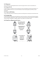
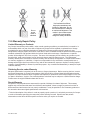
1
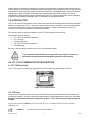
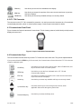
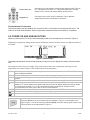
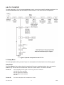
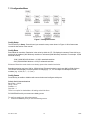
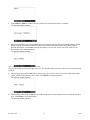
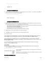
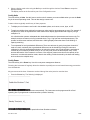
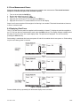
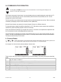
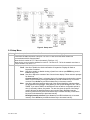
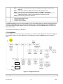
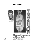
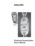
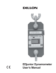
LTL 730
Dynamometer and Crane Scale
User’s Manual
Cooper Instruments and Systems
PH: 540-349-4746 • FAX: 540-347-4755
www.cooperinstruments.com
CF 150 LTL 730
ii
5/16/06
CONTENTS
1.0 Specifications .................................................................................................................... 1
2.0 Safe Operation .................................................................................................................. 1
2.1 Radio Safety .................................................................................................................. 2
2.2 Radio Communications Reliability.................................................................................. 2
3.0 Introduction........................................................................................................................ 3
4.0 LTL 730 & Communicator Description............................................................................... 3
4.1 LTL 730 Front Panel ...................................................................................................... 3
4.2 LTL 730 Connector ........................................................................................................ 4
4.3 Communicator Front Panel ............................................................................................ 4
4.4 Communicator Keys....................................................................................................... 4
5.0 Power On and Annunciators.............................................................................................. 5
6.0 LTL 730 Setup ................................................................................................................... 6
6.1 Setup Menu.................................................................................................................... 6
7.0 Configuration ..................................................................................................................... 9
7.1 Configuration Menu...................................................................................................... 10
8.0 LTL 730 Operation........................................................................................................... 14
8.1 Display Modes ............................................................................................................. 14
8.2 Force Measurement ..................................................................................................... 14
8.3 Force Measurement Rezero ........................................................................................ 15
8.4 Displaying Peak Force ................................................................................................. 15
9.0 Communicator Operation................................................................................................. 16
9.1 Powerup Display .......................................................................................................... 16
9.2 Setup Menu.................................................................................................................. 17
9.3 Config Menu................................................................................................................. 18
9.4 Communicator Print Formats ....................................................................................... 19
10.0 General Information....................................................................................................... 20
10.1 Changing Batteries .................................................................................................... 20
10.2 Battery Life................................................................................................................. 20
10.3 Care ........................................................................................................................... 20
10.4 Radio Information....................................................................................................... 20
10.5 Installing Spacers....................................................................................................... 21
11.0 Common Configurations ................................................................................................ 22
12.0 FCC Information ............................................................................................................ 23
12.1 Modifications .............................................................................................................. 23
13.0 Troubleshooting............................................................................................................. 23
14.0 Weighing and Force Measurement Practice.................................................................. 24
14.1 Load Centering .......................................................................................................... 24
14.2 Alignment ................................................................................................................... 25
14.3 Proper Pin Fit ............................................................................................................. 25
14.4 Torque and Bending .................................................................................................. 25
14.5 Certified Gear............................................................................................................. 25
14.6 Good Force Measurement Practice ........................................................................... 25
15.0 Warranty Repair Policy .................................................................................................. 26
CF 150 LTL 730
iii
5/16/06
1.0 SPECIFICATIONS
Communicator Specifications
Dynamometer Specifications
Enclosure: Designed to NEMA 3 / IP44 with optional sleeve.
Suitable for protected outdoor use.
Instrument size: 9.0 x 4.6 x 1.8 inch (228 x 117 x 45mm).
Accuracy: Not applicable. Only sends and receives digital
information.
Display: 128 x 64 dot-graphic LCD display can show full
readings up to 5 instruments.
Battery life: 60 hours wireline, 20 hours radio using four AA
alkaline batteries under typical use.
Operating temperature: -4° F to 140° F (-20° to 60° C).
Connectors: Sealed connectors may be used for serial
communications and wired connection to an LTL 730
dynamometer.
RS-232 communication: Print or extract data easily.
Continuous output can drive a scoreboard. Configurable poll
character.
Included with remote: Carry case and batteries.
Accessories: Rubberized case protector sleeve. Remote
wall mount bracket. Serial and remote cable assemblies.
Enclosure: Designed to NEMA4X/IP55. Suitable for
continuous outdoor use.
Accuracy: 0.1% of capacity.*
Repeatability: 0.1% of capacity.*
*1 part in 1000 display mode with Cooper Instruments
provided shackles.
Factor of safety: 2.5K to 10K = 7:1 USF
25K to 100K = 5:1 USF, 220K to 330K 4:1 USF
Body Protection: Aluminum capacities are anodized. Alloy
steel capacities are electroless-nickel plated.
Bearings: Unmatched repeatability attained by needle
bearings in shackle pin holes up to LTL 730 10K. Shackle
pin acts as inner race.
Shackles: Forged industry standard anchor shackles.
Models up to LTL 730 10K use precision machined shackle
pin. Higher capacities use forged pin.
Display: 128 x 64 dot-graphic LCD display shows up to 6
digits 1.0” (26mm) high plus annunciators and softkeys.
Digits are .11 inches (7mm) thick for unmatched readability.
Display update rate: 2 times per second.
Connector: Recessed sealed connector may be used for
serial communications or connection to a Communicator
remote.
RS-232 / RS-485 communication: Print or extract data
easily. Continuous output can drive a scoreboard.
Configurable poll character.
Calibration: Traceable to the National Institute of
Standards and Technology. Certificate included with curve
of readings. Passes only with three consecutive confirming
runs, with all points in specification.
Battery life: 320 hours typical use with two C-cell alkaline
batteries. 40 hours typical with Radio Link system.
Operating temperature: -4° F to 140° F (-20° to 60° C).
Included with instrument: Carry case, batteries, manual
and certificate of calibration. LTL 730 50K and LTL 730
100K with shackles include shackle crate and spacers.
Options: Shackles. 2.4 GHz radio board. Display backlight.
Approval: FCC ID: KQL-PKLR2400
CAN ID: CAN2268391158A
CE #: 89/336/EEC, 98/37/EEC, EN61000-4
Registration: 595129
Radio Specifications
FCC Certified: For unlicensed low power devices. No radio
licensing or permits required for normal operation.* (In the
US and Canada. Check local ordinances in other countries.)
Frequency: 2.4 GHz spread-spectrum operates between
2.402 – 2.478 GHz. Continuously and automatically changes
frequencies many times per second for consistent, reliable
communications.
Output Level: 10 mW (20 dBm)
Display Update Rate: 2 times per second with single
dynamometer. Multi-instrument networks result in reduced
updates.
Number of networks: 63 remotes can operate
independently in the same airspace with unique channels.
Number of links remote can control: Up to 15 addresses
are available per network channel.
Configuration: Address and Network channels are front
panel configurable.
Antenna: Integral antenna.
Range: Open-air – Up to 300 feet, line-of-sight.
Indoors – Dependent upon installation site with 150 feet
common.
2.0 SAFE OPERATION
If you overload this dynamometer you could suffer severe injuries or death. The
total load on the dynamometer should NEVER exceed the rated capacity!
CAUTION: Remove batteries from instrument when using the external AC power
supply.
Keep all the following in mind as you use the LTL 730 dynamometer.
The system capacity is equal to the rating of the dynamometers. The shackle rating should not be used to
determine lift capacity of the system.
The shackles are rated in metric tons. Thus the 12-ton shackles are rated to 26,450 lbf and are suitable for use
on the 25,000 lbf dynamometer.
CF 150 LTL 730
1
12/08
Any zeroed deadload must be considered as part of the ultimate load.
Although this instrument has a substantial overload protection rating, the instrument should not be used above
the rated capacity. Doing so can significantly impact fatigue life of the instrument and cause premature and
abrupt failure. If a higher capacity reading is needed, Cooper Instruments insists that a larger instrument be
used.
Safety is always a concern in overhead lifting and tensioning applications. To limit your liability always insist
upon factory supplied shackles and pins and factory tested and certified safe optional equipment. All COOPER
INSTRUMENTS products are designed to meet the published Safe Working Load (SWL) and Ultimate Safety
Factor (USF) standards of the United States Military.
Do not grind, stamp, drill or deform the metal on the dynamometer body in any way. Protect the instrument from
impact in use and storage.
Any significant damage or deformation to the loading element is cause for evaluation by Cooper Instruments,
particularly in the element side members to the right and left of the display.
Relieve all torsional and off axis loads.
Apply load in the center of the shackle bow with this instrument. Off center loading results in substandard
performance.
Instrument requires time to stabilize when changing temperatures.
Use only the hardware supplied with this instrument. If no hardware was supplied, insure that the mating pin and
shackle bow is equivalent to the hardware used at calibration. Otherwise substandard performance or failure
can result.
Cooper Instruments recommends only using qualified rigging hardware and cannot be responsible for
unapproved hardware.
This instrument is not designed for the following:
• Applications that see rapid, dramatic temperature swings or thermal shock. Wide variation in readings
can occur.
• Environments with high electromagnetic fields such as cranes employing electromagnets to lift metal.
These induce trace voltages that are picked up within the load cell lead wiring and appear as inaccurate
loads.
• Intrinsically safe environments. This unit has not been Factory Mutual tested.
2.1 Radio Safety
The radiated output power of this device is far below the FCC radio frequency exposure limits. Nevertheless, the
device shall be used in such manner that the potential for human contact during normal operation is minimized.
When connecting an external antenna to the device, the antenna shall be placed in such a manner to minimize
the potential for human contact during normal operation. In order to avoid the possibility of exceeding the FCC
radio frequency exposure limits, human proximity to the antenna shall not be less than 3 inch (7.5 cm) during
normal operation. The antenna is located at the connector panel on the Communicator.
2.2 Radio Communications Reliability
Low power radio systems should not be used in applications where timely updates of
readings are required for safety purposes.
CF 150 LTL 730
2
12/08
Radio systems are vulnerable to interference, resulting in delays between the dynamometer scale and remote.
In some instances of interference, the display shown on the remote may be several seconds old. This can result
in a hazardous situation when the system is used as the reference for acceptable loads in cases such as proof
loading and monitoring of binding or overload. In these applications where timely updates are critical, a
communication cable should be used to physically connect the LTL 730 and Communicator remote (see setup
of RS-485 communications). Alternately, the LTL 730 display can be observed directly.
3.0 INTRODUCTION
The LTL 730 electronic dynamometer from Cooper Instruments is a force measurement load sensor and digital
readout in one instrument. The LTL 730 can be used to measure tension or weight. It can operate stand-alone
or be coupled with a remote Cooper Instruments Communicator, via radio communication or direct wire
connection, for improved convenience, functionality and safety.
This manual covers the setup and operation of the LTL 730 and optional Communicator.
This manual covers the following:
• LTL 730 & Communicator Description
• LTL 730 Setup
• Communicator Setup
• LTL 730 & Communicator Operation
• Troubleshooting
Be sure to read the safety precautions found in the Safe Operation section.
If you overload this dynamometer you could suffer severe injuries or death. The
total load on the dynamometer should NEVER exceed the rated capacity!
4.0 LTL 730 & COMMUNICATOR DESCRIPTION
4.1 LTL 730 Front Panel
The LTL 730 comes in several weight capacities. All have the same front panel, shown in Figure 1.
Figure 1. LTL 730 front panel
LTL 730 Keys
There are four “hard” keys and four “soft” keys. The hard keys are permanently labeled and the soft keys are
just below the display. The soft key functions change and the key label appears above each key on the display.
Sometimes the individual soft keys are referred to as the F1, F2, F3 and F4 keys as numbered from left
to right.
If you press and hold the ZERO key for five seconds, the LTL 730 display will show the zero reference
calibration point.
On/Off key
CF 150 LTL 730
Use this key to turn the unit on and off.
3
12/08
Zero key
ESC key
Arrow key
Use this key to zero the force indicated on the display.
Use this key to escape from portions of the menu structure and return to previous
choices or displays.
Use this key to access any available soft keys not currently viewed.
4.2 LTL 730 Connector
The connector on the LTL 730 is recessed for protection. It is used to connect the instrument to a Communicator
remote display/controller, printer or external power supply. Contact Cooper Instruments for details.
4.3 Communicator Front Panel
Figure 2 shows the Cooper Instruments Communicator. This is a battery powered, radio-linked (or wired) remote
display and control unit.
Figure 2. Cooper Instruments Communicator
4.4 Communicator Keys
The Communicator has the same keys as the LTL 730 but also some extra ones. They are all explained below:
If you press and hold the ZERO key for five seconds, the Communicator will reset the active LTL 730 to the zero
reference calibration point.
On/Off key
Use this key to turn the unit on and off. Also, when in Radio Mode, this
key will access a menu for further options.
ZERO key
Use this key to zero the force indicated on the LTL 730 and
Communicator displays.
ESC key
Use this key to escape from portions of the menu structure and return
to previous choices or displays.
Arrow key
Use this key to access any available soft keys not currently viewed.
Up and Down key
Use these arrow keys to move through menu choices, when
applicable. Also scrolls through any active links.
Remote Setup key
CF 150 LTL 730
Use this key to access the Setup menu.
4
12/08
Display Mode key
Use this key to cycle between Communicator display modes. They are
LTL 730 specific force value, LTL 730 specific peak value, multiple
display of force values and multiple display of peak values.
Keypad keys
Use these keys to enter numeric characters. Use for address
assignments and other miscellaneous data entry.
Communicator Connectors
The Communicator may have between 2-3 connectors. CELL is for wireline communications with an LTL 730.
COM1 is for serial communications. AUX is not presently used and is either nonfunctional or not installed.
5.0 POWER ON AND ANNUNCIATORS
When you power up the LTL 730 you will see a display similar to the example shown on the left in Figure 3.
Depending on permission settings and/or revision of firmware, various soft keys may be in a different location or
not visible.
Figure 3. Initial displays
The display sample above shows several symbols you may see on your display but usually not all at the same
time.
lbf and kgf are units of force, not weight. They will be close to their mass counterparts, lb and kg, for most
applications and at most locations. See Config>Units for more information.
Force
lbf
~
Y
(Y) (Y)
This tells you that the display is showing live force measurement at the moment. Will show Peak
when viewing Peak Mode.
Current unit of measure is lbf in this example. May also be kgf, N, or up to 2 other custom units.
Motion symbol. This appears when the force is in motion. This symbol disappears when motion
ceases.
This shows the radio is configured ON but is not in communications with any Communicator.
The battery in the device is low and the radio section has been turned off. The device will continue to
display (LTL 730 will display force applied and Communicator will display dashes) but will be unable
to communicate by radio or, LTL 730 or the Communicator are improperly configured for RF
communications on Comm port #2 with no RF PC board installed.
2 Ys indicate the Communicator is in communications with an active LTL 730.
Battery annunciator. This shows approximate remaining battery life.
Capture of a new peak value. This annunciator will remain lit for a few seconds.
Press the Arrow key to move between the two displays in Figure 3. In the display on the
right in Figure 3, one of the soft keys is labeled Setup. Press this and you gain access to the
soft keys shown in the Setup Menu in Figure 4.
CF 150 LTL 730
5
12/08
6.0 LTL 730 SETUP
To begin using the LTL 730, it is recommended that you set it up to suit your specific needs and equipment. You
can access the SETUP menu with the softkeys. Refer to section 11.0 for some common configurations.
Same as
Communicator
Same as
Communicator
Name of
LTL 730
Figure 4. Operator setup menu for the LTL 730
6.1 Setup Menu
Press the appropriate soft key shown in Figure 4 to accomplish the functions listed on the following pages.
Setup Ptfmt
Press the Ptfmt soft key to select the print format that will be sent to a peripheral printer when you press the
Print soft key. Choose from the formats below. Data sent is shown below. The default is format #1.
Format #1
Current displayed value (peak or live force) plus unit of measure
104.5 lbf (live force example)
302.5 lbf (peak force example)
104.5 lbf (dual mode example)
302.5 lbf
Format #2
Live force value plus unit of measure on 1st line
CF 150 LTL 730
6
12/08
Peak force and unit of measure on 2nd line
104.5 lbf
302.5 lbf
Format #3
Live force value plus unit of measure on 1st line
Peak force and unit of measure on 2nd line
Descriptive prefixes on each line
Force 104.5 lbf
Peak 302.5 lbf
Format #4
Fixed position output. Works well with RS-232 utilities, such as WedgeLink, for parsing into a
spreadsheet such as Microsoft Excel. (comma- separated).
Excel
1
2
A
104.5
302.5
B
lbf
lbf
Fixed characters.
Position
Description
1-8
Live force number
10-16
Displayed unit of measure (up to 7 characters)
18-25
Peak force number
27-33
Displayed unit of measure (up to 7 characters)
9, 17, 26
Commas
34
Carriage return
Example 1
<sp><sp><sp>104.5,<sp><sp><sp><sp>lbf, <sp><sp><sp>302.5,<sp><sp><sp><sp>lbf<CR>
Example 2 (custom unit)
<sp>140000.,<sp><sp><sp><sp><sp>kg,<sp>165450., ,<sp><sp><sp><sp><sp>kg<CR>
This would yield (shown in courier):
111111111122222222223333333333444444444455555555
123456789012345678901234567890123456789012345678901234567
104.5,
lbf,
302.5,
lbf,<CR>
140000.,
kg,
165450.,
kg,<CR>
Format #5
Live force, unit of measure, peak force, unit of measure. All tab separated.
104.5<tab>lbf<CR> (if presently displaying live readings)
302.5<tab>lbf<CR> (if presently displaying peak readings)
104.5<tab>lbf<tab>302.5<tab>lbf<CR> (if presently displaying dual mode)
Setup Misc
Press the Misc key to access the following soft key set (refer to Figure 4):
Press this soft key to enable or disable the “display flash” feedback. If enabled, the press of a key
Flash
causes the display to momentarily flash to give you a visual feedback that the key was activated.
Press this soft key enable or disable if a press of the Zero key also clears the Peak force value. If you
Zero
enable this function, press the Zero key to clear the Peak force and zero the load. If you disable the
function, the Zero key will only zero the load. Peak force remains in effect and will only be cleared
with the Clear function during operation.
CF 150 LTL 730
7
12/08
Contr
Blite
Press this key to adjust the contrast of the LCD display. Press the Up soft key to lighten the contrast.
Press the Down soft key to darken the contrast. There is a keypad shortcut for increasing and
decreasing contrast. While in normal display mode press Arrow key and F2 simultaneously to
increase contrast.
There is a keypad shortcut for increasing and decreasing contrast. While in normal display mode
press Arrow key and F2 simultaneously to increase contrast. Press Arrow key and F1
simultaneously to decrease contrast.
Sometimes the individual soft keys are referred to as the F1, F2, F3 and F4 keys as numbered
from left to right.
If the optional backlight is installed, press this key to adjust the backlight brightness and sleep timer
functions. Press the Inten soft key to set the background brightness. Press the Mode soft key to set
the backlight configuration options. There is a keypad shortcut for increasing and decreasing backlight
intensity.
Press Arrow key and F4 simultaneously to increase intensity.
Press Arrow key and F3 simultaneously to decrease intensity.
Use of the backlight will affect battery life.
Setup About
The next soft key is the About. The About menu shows an assortment of information about your instrument.
This can be handy for maintaining calibration, troubleshooting or determining if the firmware can be upgraded.
Press this and access the following soft key set (refer to Figure 4):
Device Press this to see software revision and dynamometer information.
This soft key access the following soft key set:
Calib
Points Press this key to display the calibration loading points. This is useful information that
can be keyed in manually in the event instrument memory is ever accidentally overwritten or
corrupted.
Print Press this key to transmit all the calibration information available to a serial printer or
computer.
Cooper Instruments suggests that calibration data be recorded and saved.
O.Load
Zero
Ntwrk
Lists the number of overloads that have occurred since the last calibration.
Lists the current zero point compared to the calibration zero point. If the zero point has moved
significantly, this may indicate a serious overload has occurred and the instrument should be returned
for service.
Lists radio information - the enabled channel and identifier.
Setup Test
The Test functions can help service technicians remotely diagnose your instrument by showing information on
key internal functions. Typically these menus will have significance only to trained technicians. You may look at
these menus without technical guidance, but the information may have little meaning, or an error may be
reported that may not exist. Press this key to access several items described below (refer to Figure 4):
Press this key to perform a battery test. This shows the battery level in A-D counts and approximate
Batt
voltage. Voltage is not calibrated.
Press this key to test the A-D section of the LTL 730. You need to apply force to change the counts
A-D
and test the unit. The A-D is the electronics portion that converts analog load cell signal to digital
numbers.
Disp.
Press this key to perform a display test. Stop the test by pressing the ESC key.
Press this key to perform key tests. Any key pressed will be reflected in the display. Press ESC to end
Keys
the test.
Press this key to perform a self-test of the radio’s system.
Ntwrk
CF 150 LTL 730
8
12/08
Comm
The serial test is an internally conducted diagnostic that requires a jumper across transmit and
receive. This requires a plug or cable assembly. Pressing the Serial soft key accesses the following
soft keys:
COM1 Press this key to test COM1 in a loopback test.
COM2 Press this key to test COM2 in a loopback test.
To perform a COMM test, the unit must be configured to use RS-232 communications.
7.0 CONFIGURATION
The configuration menu is a group of settings that may be password protected if desired to prevent operators
from making significant system changes. It is used to configure the following:
• radio network
• resolution
• communication ports
• power up display mode
• units of measure
• power management
• password management
• system default reset
To access the configuration menu, press the Config soft key shown in Figure 5.
Figure 5. Accessing Config soft key and menu
The display prompts for a password. See Figure 6.
Figure 6. Password screen
Use the Num keys to enter the first character of the password and the Adv key to move to the next character.
When you are done press the Enter key and the soft keys shown in Figure 7 become available.
The default password is “0”. If the password has been changed and forgotten, contact Cooper Instruments for
assistance.
CF 150 LTL 730
9
12/08
7.1 Configuration Menu
Figure 7. Configuration menu
Config Setup
The first soft key is Setup. Press this and you access the setup menu shown in Figure 4. All its features are
covered in that section of the manual.
Config Reso
Reso stands for resolution. Resolution is the value by which the LTL 730 displays increments. Press this key to
set the unit to standard (1000 divisions) resolution or enhanced (5000 divisions) resolution. For example: 10,000
lbf would count by
10 lbf (10,000 lbf/1000 divisions = 10 lbf) in standard resolution
2 lbf (10,000 lbf/5000 divisions = 2 lbf) in enhanced resolution
Enhanced Resolution mode drains more battery power than standard resolution.
Standard resolution may have 1000 or 1250 divisions. Enhanced resolution may have 4000 or 5000 divisions.
This follows normal display increment practice of changing by 1, 2, 5 or a multiple or submultiple of those
numbers (e.g. 10, 20, 50, .1, .2, .5, etc.).
Config Comm
Press this key to enable or disable radio communication and configure serial ports.
Default Serial Communications
Baud Rate = 57600
Parity = None
Databits = 8
Stop bits = 1
There is no option for handshakes. All settings should be None.
RS-232/RS-485 activity consumes more battery power.
To configure serial ports, follow these steps:
1. Press the Comm key and you see the following screen:
CF 150 LTL 730
10
12/08
2. Press COM 2 or COM 1. COM2 is used to configure the optional radio board, if installed.
The following display appears.
3. Select a transmission level using the Sel keys to scroll through the four choices; Disabled (default), RS232,
RS485, and RF. RF stands for Radio Frequency and means transmission would be by radio (requires
optional radio board). Press Enter to accept the setting. If you set the Trans Level to RF, steps 3-5 are
automatically set and do not appear.
The following display appears:
The * indicates which option is currently selected.
The second serial port requires a larger connector. The standard 4-pin connector only has one serial connection
(COM 2).
4. Select a baud rate using the Sel keys to scroll through your choices. Choices are 1200, 2400, 4800, 9600,
19200, 38400, 57600 (default), and 115200. Press Enter to accept the setting.
The following display appears:
5. Select a parity value using the Sel keys to scroll through your choices. Choices are none (default), odd and
even. Press Enter to accept the setting.
The following display appears:
CF 150 LTL 730
11
12/08
6. Select a databit value using the Sel keys to toggle between the two choices; 7 or 8 (default). Press Enter to
accept the setting. The following display appears.
7. Select a mode of communication you want using the Sel keys to scroll through these choices; Continuous, ,
Poll, Remote and Prink Key Only. Press Enter to accept the setting.
If you choose Continuous, you will be prompted to select a print format for the transmission and a rate at
which you want to send the transmission.
If you choose Poll you will be prompted to enter a poll character.
Choose Remote for wireline communications.
Choose Print Key Only to print only when the Print key is pressed.
8. Repeat steps 2-7 for the other serial port if it needs configuring.
9. Press ESC to return to the first soft key set of the Configuration menu.
If you enable the radio:
You are asked to enter a Radio Channel. Your LTL 730 and Communicator must be on the same channel to
function together. Key in a number from 1 through 64. 1 is the default setting. Press Enter to accept.
You are asked to enter a Network ID#. This is a unique address number (1-15) so the Communicator only
speaks to one instrument at a time without “cross-talking.” Use the available soft keys to enter a number (1-15),
then press Enter to accept.
You are then asked to key in an alternate network identifier. Use the available soft keys to enter alpha
characters, then press Enter to accept.
Config Mode
The next menu key is the Mode key. Use this key to choose what display mode is active upon powerup.
1. Press the Mode key. The following is displayed:
See the Display Modes section under LTL 730 Operation for more detail on
display modes.
Asterisk shows current selection. (Last) causes display to power up in same
mode as when last powered down.
CF 150 LTL 730
12
12/08
2. Select a display mode value using the Sel key to scroll through the choices. Press Enter to accept the
displayed setting.
The display returns to the first soft key set of the Configuration menu.
Config Units
The next soft key is Units. Use this item to set the units of measure you want available when you use the Units
key in the normal operating mode. This can also assign custom units.
Custom units are typically used for any of three purposes:
1. To display a unit of measure not found in the standard options, such as ton, tonne, dyne, or KIP.
2. To apply a multiplier when multipart line systems or other static line arrangements are used. For example, if
a 4-part line is used, the dynamometer at the dead end can display approximate total weight by using a
multiplier of 4.
It is critical that the operator understands the relationship between the dynamometer and custom unit. For
example, assume a custom unit of kg is entered where 1 kg = 5 kgf (as seen at the dynamometer). The
operator could become confused, and think that a 1000 kg display means that there is still 4000 kg of
capacity remaining.
3. To compensate for local gravitational differences. There are variances in gravity throughout the world. If
used as a scale, variances due to gravitational differences can be handled by having the instrument
calibrated on-site with certified dead weights or by using the custom units. Simply divide the gravitational
constant at your location by 9.80665 m/ss (or 32.1741 ft/s2) and use this as the multiplier entry. A less
accurate alternative: If the constant is not known, lift a weight of known mass close to the capacity of the
instrument. In enhanced resolution mode, observe the reading. Divide the actual by the observed reading
and use this as the multiplier entry.
Config Power
The next soft key is the Power key. Use this to set power management features.
Powering the instrument off regularly allows the batteries to partially recover and maximizes energy extractions
from the batteries.
Key presses reset the timer. Characters received through the serial port also reset the timer.
1. Press the Power key. The following is displayed:
Auto-Shutdown powers off the instrument automatically. The instrument can be programmed for a fixed
operating time or programmed to shut down after a period of inactivity.
Timer reflects the period required to pass before Auto-Shutdown activates.
CF 150 LTL 730
13
12/08
The following screen is displayed:
Select Yes if you only want the instrument to automatically shut down when there is inactivity. Select No if you
want the instrument to power down after the timer counts down, regardless of any activity.
Config ChPwd
The next soft key is ChPwd. Use this to change the password used to access the configuration menu.
IMPORTANT: Changing the password denies access to this menu without entry of the new password.
Contact Cooper Instruments if you lose your password.
Config Reset
The last soft key in this set is the Reset soft key. Use this to reset the system to its factory default settings.
This concludes the Configuration menu section.
8.0 LTL 730 OPERATION
8.1 Display Modes
The LTL 730 has several display modes accessible by pressing the Mode soft key. See Figure 8.
The first display mode when you power up is the live force measurement mode.
Press the Mode soft key and the display changes to peak measurement mode. This mode shows the peak force
applied to the LTL 730 since the last peak clearing action. Delete the peak reading by pressing the Clear soft
key.
Press the Mode soft key again and the display shows live force and peak readings simultaneously.
Press the Mode soft key again and the display returns to the force measurement mode.
Power up display modes may be configured. See Config>Mode section.
8.2 Force Measurement
Follow these steps to perform a gross force measurement.
1.
2.
3.
4.
Turn on the unit with the On/Off key.
Remove any weight from the LTL 730.
Zero the LTL 730 by pressing the ZERO key.
Apply the force to the LTL 730 and read the gross force on the display.
You can change the units of measure of the display by pressing the Units soft key. See note below. Zero
reference is maintained after instrument power off and will be recalled with the next power-on. Zero reference
may be lost if battery power is removed.
Unit of measure can be changed only if multiple units are enabled in the Configuration menu.
CF 150 LTL 730
14
12/08
8.3 Force Measurement Rezero
Rezeroing allows the weight or load of fixturing to be invisible to the measurement. The zeroed load must
always be considered as part of the maximum capacity.
1.
2.
3.
4.
5.
Turn on the unit with the On/Off key.
Remove any weight from the LTL 730.
Zero the LTL 730 by pressing the ZERO key.
Apply the tare force to the LTL 730 and press the ZERO key.
Apply the force to the LTL 730 and read the net force on the display.
Steps 2 and 3 are not required if the weight of the fixturing is not needed. This should be maintained, however,
to know cumulative loads.
8.4 Displaying Peak Force
The LTL 730 will store the peak force applied until that reading is cleared. To display the peak force applied to
an LTL 730, from the force measurement mode, press the Mode soft key. The display changes to display menu
#2 shown in Figure 8, which is the peak display mode. The peak force is displayed. You can clear this by
pressing the Clear soft key.
Peak reading is maintained after instrument power off and will be recalled with the next power-on. Peak reading
may be lost if battery power is removed.
Figure 8. Display mode menu
Press the Mode soft key repeatedly until the desired display mode is reached.
CF 150 LTL 730
15
12/08
9.0 COMMUNICATOR OPERATION
Use the UP and DOWN arrow keys on the Communicator to scroll through the displays of all
active LTL 730s and a total screen.
The Cooper Instruments Communicator is a remote display and control module designed to work with the LTL
730. It can be connected by wire or can communicate by radio if both the Communicator and LTL 730 are
equipped with optional radio boards.
The Communicator may simultaneously view and control several dynamometers at one time. Each is monitored
individually by assigning unique numeric identifiers to each (addresses).
Several Communicators may operate in the same airspace if they are on different channels.
For best performance always have different identifiers for LTL 730s within the same network and use different
channels for systems operating anywhere close to one another.
Since most functions are identical, you should refer to the LTL 730 section for comprehensive explanation and
the Communicator’s section will highlight differences that exist.
The Communicator is designed to be similar in layout and function to an LTL 730 to make operation easy and
intuitive. The main screen appears as it does on the LTL 730 except that the Mode soft key has been blanked.
This has an actual hard key on the remote.
9.1 Powerup Display
These annunciators on the Communicator display show battery level and radio operation for
the Communicator (right side pair) and the active LTL 730 (left side pair).
An example of a Communicator’s powerup display is shown below:
There are three soft keys on the first display and 4 on the second display. The soft key functions are described
below:
Changes the displayed unit of measure. Each press advances the display through this sequence; lbf,
Units
kgf, N, custom 1, custom 2.
Outputs serial data to peripheral devices attached to COM 1.
Print
Clears the peaks on all LTL 730s currently in communication with the remote.
C.All
Clears the current peak value of the active LTL 730.
Clear
Resets all LTL 730s to calibration zero reference point.
UZ.All
Zeros all LTL 730s currently in communication with the remote.
Z.All
Accesses the Setup menu shown in Figure 9.
Setup
Config Accesses the Config menu shown in Figure 10.
CF 150 LTL 730
16
12/08
Figure 9. Setup menu
9.2 Setup Menu
Ptfmt
Ntwrk
Misc
Select from print formats 1-7. See Print Formats section on the following pages.
Setup the network.
First choice is Radio Channel #. Can pick 1-64. All LTL 730s set to this same number will
communicate with this Communicator.
Next choice is number of LTL 730s in the network. Pick from 1-15.
Next choice, you must set the address for each LTL 730. Each LTL 730 in the network must have a
unique number. Pick from 1-15.
Lets you setup the following items:
Flash Use this to enable the visual confirmation of keystrokes. Display will flash on
keystrokes if enabled.
Zero Use this to enable or disable clearing of peak force values upon ZERO key press or
Z.All soft key press.
Contr Use this to adjust the contrast of the Communicator display. Follow onscreen prompts
for directions.
Contrast shortcut There is a keypad shortcut for increasing and decreasing contrast.
While in normal display mode press Arrow key and F2 simultaneously to increase
contrast. Press Arrow key and F1 simultaneously to decrease contrast.
Blite Use this to adjust the intensity and mode of the optional backlight. Intensity adjusts
the brightness of the backlight. Using Mode you can set the backlight to OFF, ON, or
TIMER. If you select TIMER, the backlight will shut off after a configurable period of
time (in seconds), without a keystroke. You are also given the option of choosing if
motion will reset the backlight timer to start counting again. Backlight intensity
shortcut Press Arrow key and F4 simultaneously to increase intensity. Press Arrow
key and F3 simultaneously to decrease intensity.
Backlight intensity shortcut Press Arrow key and F4 simultaneously to increase
intensity. Press Arrow key and F3 simultaneously to decrease intensity.
CF 150 LTL 730
17
12/08
Test
About
Lets you test the following items:
Batt
Press this to check the battery condition. Display shows voltage condition of the
batteries.
Disp Press this to perform a display test. Press any key to stop the test.
Keys Press this key to test individual key function. Press ESC to stop the test.
Comm Press this key to perform LOOP/NOLOOP tests onCOM1. Press ESC to return to
Test soft key display. COM1 must be enabled in Config menu to test.
Ntwrk Press this key to perform a radio test.
Press this soft key to see the following information:
• Communicator Serial Number
• Firmware part number
• Revision level of software
Press ESC repeatedly to return to normal operation. If you have made changes you will be prompted to save the
changes. Press the Save soft key to save the changes and return to normal operation. Press the noSave soft
key to disregard any changes made and return to normal operation. Press the Cancel soft key to return to the
Setup menu screen.
This completes the Setup menu description.
9.3 Config Menu
The configuration menu, shown in Figure 10, allows you to set the items described below. Press the Config soft
key to enter the menu. You will be asked to key in a password, then press the Enter soft key to access the
menu.
Same as
LTL 730
Number of LTL
730 in ntwrk
Same as
LTL 730
Network ID
Address for LTL
730 1
Figure 10. Config(uration) menu
Mode
Press this to set the display mode that will be active upon power-up.
CF 150 LTL 730
18
12/08
Units
Power
Chpwd
Reset
Press this key to set the following:
Choice of power-up unit of measure
Enable or disable lbf, kgf, N, custom unit 1 and 2
Press this to set the following:
Enable Auto-shutdown (Y/N)
Shutdown Timer (set minutes before idleness causes unit to shut off)
Press this to change the Config menu password.
Press and you are given the choice of resetting the Communicator to its factory defaults.
9.4 Communicator Print Formats
Press the Ptfmt soft key to select the print format that will be sent from the Communicator on Com 1 to a
peripheral printer when you press the Print soft key. Choose from the formats below. Data sent is shown below.
The default is format #1.
Format #1
Format #2
Format #3
Format #4
Current displayed value (peak or live force) plus unit of measure on the active LTL 730 only.
104.5 lbf (live force example)
302.5 lbf (peak force example)
Live force value plus unit of measure on 1st line and Peak force and unit of measure on 2nd line
for active LTL 730 only.
104.5 lbf
302.5 lbf
Live force value plus unit of measure on 1st line and Peak force and unit of measure on 2nd line
with descriptive prefixes on each line for active LTL 730 only.
Force 104.5 lbf
Peak 302.5 lbf
Fixed position output for active LTL 730 only. Works well with RS- 232 utilities, such as
WedgeLink, for parsing into a spreadsheet such as Microsoft Excel.
Excel
1
2
A
104.5
302.5
B
lbf
lbf
Fixed characters.
Position Description
1-8
Live force number
10-16
Displayed unit of measure (up to 7 characters)
18-25
Peak force number
27-33
Displayed unit of measure (up to 7 characters)
9,17,26
Commas
34
Carriage Return
Example 1
<sp><sp><sp>104.5,<sp><sp><sp><sp>lbf,<sp><sp><sp>302.5,<sp><sp><sp><sp>lbf<CR>
Example 2 (custom unit)
<sp>140000.,<sp><sp><sp><sp><sp>kg,<sp>165450., ,<sp><sp><sp><sp><sp>kg<CR>
This would yield (shown in courier):
111111111122222222223333333333444444444455555555
123456789012345678901234567890123456789012345678901234567
104.5,
140000.,
lbf,
kg,
302.5,
165450.,
lbf<CR>
kg<CR>
Format #5 Live force, unit of measure, peak force, unit of measure for active LTL 730 only. All tab separated.
104.5<tab>lbf<CR> (if presently displaying live readings)
302.5<tab>lbf<CR> (if presently displaying peak readings)
Format #6 Cell #, description, live force, unit of measure for all active LTL 730s plus a total.
CF 150 LTL 730
19
12/08
Example:
Cell<tab>Description<tab>Live Force<tab>Units<CR>
1<tab>North<tab>104.5<tab>lbf<CR>
2<tab>South<tab>4801<tab>lbf<CR>
Total<tab><tab>4905.5<tab>lbf
Format #7 Outputs print format #6 plus peak values for all LTL 730s.
10.0 GENERAL INFORMATION
10.1 Changing Batteries
To replace discharged batteries, unscrew the battery compartment cap on the right side of the dynamometer.
Remove the two C cells and replace them with the + poles inserted first. If the spring in the cap becomes
detached, you can reattach it by aligning the large end over the counterbored hole and turning the spring
counterclockwise while pushing the spring into the hole. The spring will work into the recess and be selfretained.
The Communicator has 4 AA batteries. To replace, remove rear battery cover and replace with fresh batteries in
the proper arrangement.
10.2 Battery Life
The time required between battery changes can vary with usage, functions enabled, temperature, duration of
use and recovery time, display update rate, battery grade and more.
To maximize battery life:
• Disable radio if not being used. Even if an optional radio board is not installed, the software will run, if
enabled.
• Disable other functions such as RS-232 and backlight.
• Warm environments result in longer battery life over cool environments.
• Use high quality alkaline batteries.
• Turn off instrument when not in use. Alkaline batteries partially recover when the instrument is off.
CAUTION: Remove batteries from instrument when using
the external AC power supply.
10.3 Care
The LTL 730 is built to be rugged and endure typical industrial and commercial use. It is still, however, a
precision instrument that should be treated with care. Store the instrument in its carry case with power off.
Remove batteries if not being used.
10.4 Radio Information
The radio technology used in the radio equipped LTL 730 and Communicator is a 2.4 GHz digital spread
spectrum system designed for communications reliability. Radio operation and the performance attained can be
difficult to predict and will vary with environment and conditions. There are locations where radio use is
impractical or even impossible.
Tips for best performance:
• Keep the Communicator and LTL 730 as close as possible together.
• Keep metal and other dense objects as far from the instruments as possible.
• Normally the higher that both the LTL 730 and Communicator are above the ground, the better the
performance and range will be.
CF 150 LTL 730
20
12/08
Many things can degrade radio signals, such as brick walls, metal reinforced concrete, machinery and even
wiring within walls. Other systems such as wireless networks and cordless phones may degrade or interfere with
operation of the Cooper Instruments radio-equipped system. As an FCC approved instrument on a license-free
radio band, the instrument must accept interference received from other devices that share the same frequency
and airspace. If other systems are colliding, it is best to isolate the device(s) that cause the interference and
then take steps to eliminate the problem which may include relocation, conditional operation or retirement of the
interfering device.
10.5 Installing Spacers
High capacity dynamometers with shackles of 50,000 lbf/20000kgf capacity and up, use spacers, Figure 11, to
insure proper centering of the dynamometer for performance and safety reasons.
Figure 11. Spacer
Do not use the dynamometer with shackles if the spacers are not installed. The LTL 730 design incorporates an
innovative method to retain these spacers, if desired, to ease shackle installation.
Place spacer on a solid surface and use a hammer to start the roll pins into the two small spacer holes. See
Figure 12.
Figure 12. Inserting roll pin
Insert through matching holes in dynamometer body. Lay the dynamometer on the spacers on a solid surface
with the roll pins protruding from the top. See Figure 13.
Figure 13. Roll pins extending above dynamometer body
Position the holes of the second spacer over the holes and tap spacer into position. See Figure 14.
Figure 14. Placing second spacer on roll pins
CF 150 LTL 730
21
12/08
A punch sized slightly smaller than the holes in the spacer may be helpful. The spacers should “sandwich” the
dynamometer body, but should not be drawn completely tight.
Remove the four large circular foam plugs from the carry case and it can continue to be used with the spacers
attached.
11.0 COMMON CONFIGURATIONS
LTL 730 being used stand-alone (no RS-232 or Communicator remote)
Key Settings (LTL 730):
COM1 Trans Level – Disabled
COM2 Trans Level – Disabled
LTL 730 connected to a computer
Key Settings (LTL 730):
COM1 Trans Level – Disabled
COM2 Trans Level – RS-232 (all other parameters should agree with peripheral such as baud, data bits &
parity)
Communicator connected to one LTL 730 by wire on CELL port
Key Settings (LTL 730 and Communicator):
COM1 Trans Level – Disabled
COM2 Trans Level – RS-485
Address: 1
Channel: 1
Communicator talking to one LTL 730 by radio
Key Settings (Communicator):
COM1 Trans Level – Disabled or RS-232
COM2 Trans Level – RF
Radio Channel (1-64): 1 (this must differ from all other Communicators in the area)
Number of LTL 730s in the network (1-15): 1
Address of LTL 730 1: 1
Key Settings (LTL 730):
COM1 Trans Level – Disabled
COM2 Trans Level – RF
Radio Channel (1-64): 1 (must match Communicator setting)
Network ID (1-15): 1
Network Identifier: (enter characters or digits to identify this specific LTL 730) (most useful if multiple LTL
730s are networked to one Communicator)
Communicator talking to four LTL 730s by radio
Key Settings (Communicator):
COM1 Trans Level – Disabled or RS-232
COM2 Trans Level – RF
Radio Channel (1-64): 1 (this must differ from all other Communicators in the area)
Number of LTL 730s in the Network (1-15): 4
Address of LTL 730 1: 1
Address of LTL 730 2: 2
Address of LTL 730 3: 3
Address of LTL 730 4: 4
Key Settings (LTL 730 1):
COM1 Trans Level – Disabled
COM2 Trans Level – RF
Radio Channel (1-64): 1 (must match Communicator setting)
Network ID (1-15): 1
Network Identifier: A
CF 150 LTL 730
22
12/08
Key Settings (LTL 730 2):
COM1 Trans Level – Disabled
COM2 Trans Level – RF
Radio Channel (1-64): 1 (must match Communicator setting)
Network ID (1-15): 2
Network Identifier: B
Key Settings (LTL 730 3):
COM1 Trans Level – Disabled
COM2 Trans Level – RF
Radio Channel (1-64): 1 (must match Communicator setting)
Network ID (1-15): 3
Network Identifier: C
Key Settings (LTL 730 4):
COM1 Trans Level – Disabled
COM2 Trans Level – RF
Radio Channel (1-64): 1 (must match Communicator setting)
Network ID (1-15): 4
Network Identifier: D
12.0 FCC INFORMATION
This device complies with Part 15 of the FCC Rules. Operation is subject to the following two
conditions:
1. This device may not cause harmful interference, and
2. This device must accept any interference received, including interference that may cause
undesired operation.
Agency Identification Numbers
US/FCC
CAN/IC
KQL-PKLR2400
CAN2268391158A
12.1 Modifications
The FCC states that any changes or modifications to this device that are not expressly approved by Cooper
Instruments may void the user’s authority to operate the equipment.
13.0 TROUBLESHOOTING
Problem
Possible Cause
Solution
LTL 730 powers on
momentarily and
turns off
LTL 730 does not
power on
Low battery
Replace with high quality alkaline batteries
Low battery
Batteries installed
backwards or no
spring contact
Software reset
Replace with high quality alkaline batteries
Insure that positive terminals of both batteries (nub) face inward
– towards the black cap. Check that spring is attached to the
battery cap.
Remove battery cap & reinstall after one minute. Attempt to turn
power on again.
Hold the Right Arrow key down while pressing the F2 key
several times to increase the display contrast. If nothing occurs,
release both keys. Press the power button and try again.
Hold the Arrow key down while pressing the F1 key several
times to decrease the display contrast.
Insure that shackles are in good working condition and aligned
Display contrast too
light
Display is
completely dark
LTL 730 does not
CF 150 LTL 730
Display contrast too
dark
Check installation &
23
12/08
Problem
Possible Cause
Solution
appear accurate
system
straight. Verify system is applying force directly through the
dynamometer with no off center or torsional loads being applied
to the instrument.
If being compared against dead-weights, check your local
gravitational constant (see Force Measurement & Weighing
Differences section). Use custom units to compensate or
calibrate on-site.
Place LTL 730 in low-resolution mode. Lift an arbitrary weight
several times as close to capacity as possible. Record each
weight reading. Do the readings differ from each other?
Calculate the standard deviation of the readings using a
spreadsheet such as Microsoft Excel. See if the deviation is
greater than 0.1% of the instrument capacity.
Place LTL 730 in low-resolution mode. Apply a known load near
instrument capacity. Check calibration date.
Bring remote closer to dynamometer. Allow several seconds to
retrain.
Local gravitational
variances
Check repeatability
Radio
communication
intermittent
Radio
communications not
working at all
Remote reading
changes to dashes
Display locks up on
marquee
Compare against a
reference load.
Low batteries.
Distance is excessive
or dead-radio pocket
Excessive radio noise
or interference in
environment
Dead batteries.
Distance is excessive,
dead radio pocket
Radio systems
initialized. No “Y”
appears
Displayed
Operating channels
matched
Excessive radio noise
or interference in
environment
Low batteries, lost
communications
Poor connection
between LTL 730 and
Communicator
Remove dynamometer and remote from the environment.
Attempt communications in an area free of local radio signals.
Bring remote closer to dynamometer. Allow several seconds to
retrain.
Enable the radio system in the COM2 configuration of both
instruments (under Comm menu).
Change batteries in the device when the is blinking
Remote and link must be on the same operating channel. See
LTL 730 and Communicator configurations of COM2 for radio
(under Comm menu).
Remove dynamometer and remote from the environment.
Attempt communications in an area free of local radio signals.
See Radio Information section of the manual.
See steps above for improving communications.
Remove batteries from LTL 730 and Communicator, replace
them and power up.
14.0 WEIGHING AND FORCE MEASUREMENT PRACTICE
The basis for all electronic force measurement or weighing is measurement of stress in a
load cell body. To obtain optimal results it is necessary to establish a few basic rules;
otherwise the effect may be a nonlinear or nonrepeatable response. Read and follow
these tips and see the illustrations on the next page.
14.1 Load Centering
For accurate performance the force acting on the unit must be in line with the unit.
Centering the load is accomplished by using the shims on each side of the load cell so
that it is centered on the shackle pin. See the illustration at right. The 50,000 lbf (20000
kgf) and higher LTL 730s also include spacers supplied with shackles.
CF 150 LTL 730
24
12/08
14.2 Alignment
Insure shackles are oriented parallel with the instrument. Apply load in the center of the shackle bow.
14.3 Proper Pin Fit
A proper fitting pin is important in order to generate an even stress distribution and avoid yield stresses. To
achieve published accuracy you must use the shackle pins and centering spacers provided by Cooper
Instruments.
14.4 Torque and Bending
Torque and bending should be avoided. Use swivels on the lifting wire for anti-torque and avoid side forces.
14.5 Certified Gear
Certified shackles and lifting gear should always be used in accordance to local laws and federal legislation.
Insure all hardware, fittings and line used to sustain the load are properly sized and rated for the installation.
Have the system evaluated by a qualified engineer if any question or uncertainty exists.
14.6 Good Force Measurement Practice
Be sure fixturing does
not bind between the
body of the LTL 730
and the shackle!
Center the load on the
shackle pin. Use
spacers to insure
centering where
applicable.
Use only with a pin
of the same
diameter and
hardness the
original factory
equipment.
CF 150 LTL 730
25
12/08
Use hardware that allows
single point attachment and
freedom of alignment. Do not
use hardware that is undersize
or restricts self-alignment. This
results in poor measurement
performance and possible
dangerous safety conditions.
Do not
torque,
bend or
sideload.
15.0 Warranty Repair Policy
Limited Warranty on Products
Any Cooper Instruments product which, under normal operating conditions, proves defective in material or in
workmanship within one year of the date of shipment by Cooper will be repaired or replaced free of charge
provided that a return material authorization is obtained from Cooper and the defective product is sent,
transportation charges prepaid, with notice of the defect, and it is established that the product has been properly
installed, maintained, and operated within the limits of rated and normal usage. Replacement or repaired
product will be shipped F.O.B. from our plant. The terms of this warranty do not extend to any product or part
thereof which, under normal usage, has an inherently shorter useful life than one year. The replacement
warranty detailed here is the buyer’s exclusive remedy, and will satisfy all obligations of Cooper whether based
on contract, negligence, or otherwise. Cooper is not responsible for any incidental or consequential loss or
damage which might result from a failure of any and all other warranties, express or implied, including implied
warranty of merchantability or fitness for particular purpose. Any unauthorized disassembly or attempt to repair
voids this warranty.
Obtaining Service under Warranty
Advance authorization is required prior to the return to Cooper Instruments. Before returning the item, contact
the Repair Department c/o Cooper Instruments at (540) 349-4746 for a Return Material Authorization number.
Shipment to Cooper shall be at buyer’s expense and repaired or replacement items will be shipped F.O.B. from
our plant in Warrenton, Virginia. Non-verified problems or defects may be subject to a $100 evaluation charge.
Please return the original calibration data with the unit.
Repair Warranty
All repairs of Cooper products are warranted for a period of 90 days from date of shipment. This warranty
applies only to those items that were found defective and repaired; it does not apply to products in which no
defect was found and returned as is or merely recalibrated. It may be possible for out-of-warranty products to
be returned to the exact original specifications or dimensions.
* Technical description of the defect: In order to properly repair a product, it is absolutely necessary for Cooper
to receive information specifying the reason the product is being returned. Specific test data, written
observations on the failure and the specific corrective action you require are needed.
CF 150 LTL 730
26
12/08