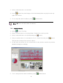
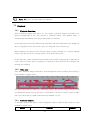
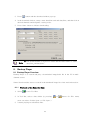
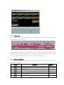
1
VMS
User Manual
(v.1.0.046)
Preface
Users installing and operating the product is required to understand this manual and relative
manuals fully before installation and operation.
All rights of the software and hardware described in the manual are protected by the patent
law.
This icon means “Note” explaining the procedure and additional
Note
information.
This icon means “Caution” explaining important information or
Caution
limitations of the operation. .
2
CONTENTS
1.
2.
3.
OVERVIEW ............................................................................................................................................ 6
1.1
INTRODUCTION .................................................................................................................................. 6
1.2
FEATURE ............................................................................................................................................ 6
INSTALLATION..................................................................................................................................... 7
2.1
SYSTEM REQUIREMENT ...................................................................................................................... 7
2.2
INSTALLATION GUIDE ......................................................................................................................... 7
SYSTEM LOGIN .................................................................................................................................... 8
3.1
4.
SITE REGISTRATION ............................................................................................................................ 8
INITIAL INSTRUCTION ....................................................................................................................... 9
4.1
SITE REGISTRATION ............................................................................................................................ 9
4.1.1
4.2
REGISTRATION ................................................................................................................................ 9
SCREEN LAYOUT REGISTRATION ....................................................................................................... 11
4.2.1
4.3
5.
REGISTRATION .............................................................................................................................. 12
USER REGISTRATION ........................................................................................................................ 14
4.3.1
USER GROUP REGISTRATION ......................................................................................................... 14
4.3.2
USER REGISTRATION ..................................................................................................................... 15
MENU.................................................................................................................................................... 17
5.1
VIEW ............................................................................................................................................... 17
5.2
SYSTEM .......................................................................................................................................... 18
5.2.1
LOG MANAGER ............................................................................................................................ 18
5.2.1.1
LOG VIEW .................................................................................................................................... 18
5.2.1.2
5.2.2
APP SETUP ................................................................................................................................... 21
5.2.2.1
STORAGE SETUP ........................................................................................................................... 21
5.3
6.
DATA SAVE............................................................................................................................. 20
SETUP............................................................................................................................................. 22
5.3.1
EDIT PASSWORD ........................................................................................................................... 22
5.3.2
USER INFORMATION ...................................................................................................................... 23
5.3.3
ALARM MANAGER........................................................................................................................ 23
VIEWER ............................................................................................................................................... 25
6.1
VIEWER OVERVIEW .......................................................................................................................... 25
3
6.2
6.2.1
IMAGE VIEW BY CONNECTING SECURITY DEVICES .......................................................................... 27
6.2.2
IMAGE VIEW BY CONNECTING CAMERAS .................................................................................... 27
6.2.3
IMAGE VIEW THROUGH THE SECOND MONITOR ............................................................................... 28
6.3
6.3.1
6.4
6.4.1
6.5
6.5.1
6.6
EVENT INFORMATION VIEW ....................................................................................................... 29
STATUS LIST.................................................................................................................................. 30
SECURITY DEVICE STATUS INFORMATION VIEW....................................................................... 30
POPUP IMAGE ................................................................................................................................. 30
THUMBNAIL IMAGE VIEW IN POPUP IMAGE WINDOW ................................................................ 31
BASIC CONTROL ............................................................................................................................. 32
PTZ CONTROL ........................................................................................................................... 32
6.6.2
RELAY OUT CONTROL ................................................................................................................ 33
6.6.3
TWO WAY AUDIO CONTROL ....................................................................................................... 34
6.6.4
COLOR ADJUSTMENT.................................................................................................................. 34
6.6.5
SCREEN SEQUENCE FUNCTION .................................................................................................. 35
6.6.6
OTHER FUNCTIONS .................................................................................................................... 35
6.7.1
CALLBACK FUNCTION .................................................................................................................... 36
SETTING AND OPERATION .......................................................................................................... 36
PLAYBACK .......................................................................................................................................... 38
7.1
7.1.1
7.2
PLAYBACK OVERVIEW ...................................................................................................................... 38
PLAYBACK OF THE RECORDED IMAGE........................................................................................ 38
SEARCH .......................................................................................................................................... 39
7.2.1
TIME SEARCH ............................................................................................................................. 39
7.2.2
PREVIEW SEARCH ....................................................................................................................... 40
7.3
PLAYBACK ...................................................................................................................................... 41
7.3.1
PLAYBACK OVERVIEW ................................................................................................................ 41
7.3.2
TIME LINE .................................................................................................................................. 41
7.3.3
PLAYBACK CONTROL.................................................................................................................. 41
7.3.4
CONTROL .................................................................................................................................... 42
7.4
7.4.1
8.
EVENT LIST ...................................................................................................................................... 29
6.6.1
6.7
7.
IMAGE VIEW .................................................................................................................................... 26
DOWNLOAD ..................................................................................................................................... 42
DOWNLOAD OF THE RECORDED DATA ....................................................................................... 42
BACKUP PLAYER ............................................................................................................................... 43
8.1
BACKUP PLAYER OVERVIEW ............................................................................................................. 43
8.1.1
PLAYBACK OF THE RECORDED DATA ........................................................................................ 43
8.1.2
TIME LINE .................................................................................................................................. 44
4
8.1.3
PLAYBACK CONTROL.................................................................................................................. 44
8.1.4
CONTROL .................................................................................................................................... 45
8.2
SMART SEARCH ................................................................................................................................ 45
8.2.1
WATER MARK SEARCH .................................................................................................................. 46
8.3
8.3.1
9.
SMART SEARCH .......................................................................................................................... 45
WATER MARK SEARCH ............................................................................................................... 46
VIDEO ENCODER ............................................................................................................................... 47
9.1
VIDEO ENCODER OVERVIEW .......................................................................................................... 47
9.2
VIDEO ENCODER START/ OPERATION ........................................................................................... 47
10.
HEALTH MANAGER....................................................................................................................... 49
10.1
HEALTH MANAGER OVERVIEW ...................................................................................................... 49
10.2
HEALTH MANAGER START/ OPERATION ....................................................................................... 49
11.
REMOTE UPGRADER..................................................................................................................... 50
11.1
REMOTE UPGRADER OVERVIEW ..................................................................................................... 50
11.2
REMOTE UPGRADER START/OPERATION .................................................................................... 50
12.
DVR SETUP MANAGER ................................................................................................................ 51
12.1
DVR SETUP MANAGER OVERVIEW................................................................................................ 51
12.2
DVR SETUP MANAGER START ...................................................................................................... 52
12.3
SETUP DATA OPEN &SAVE ........................................................................................................... 52
12.4
SETUP DATA RESET AND DVR ALL RESET ................................................................................. 52
5
1. Overview
1.1 Introduction
This program is Central Management System that is designed to control various security
devices (IP camera, DVR, NVR, Video Sever) connected from a single PC by networking.
This program consists of the multi-functions including the live image monitoring, realtime event management, security device status monitoring, and then image search,
playback, download, smart search and watermark etc.
1.2 Feature
In the program, users can register security devices without quantity limitation and it
provides a real-time monitoring of max. 128 cameras as long as VGA card in PC
supports two monitors. Users can control a function window size as each function has a
separate window.
This program manages the user account and group. It provides a separate management of
the user account by allowing the administrator to set the authority of detail features for
the group.
This program manages and saves events that were sent from many security devices. This
program reports users an alarm set with events through the pop-up message, audio and
real-time image etc.
In the network player, users can search the recorded file and play and download the
image and audio. A searching term by second is available and the preview screen enables
users to search images without playing actual images.
The recorded file with images and audios in PC can be played by File Player and it
provides a faster search of information by the smart search and water mark.
6
2. Installation
2.1 System Requirement
In order for proper operation of the program, it requires PC more than the min.
specification. With the min. specification, it only provides min. functions. For full
operation of the program, PC is required to be equipped with more than the recommended
specification.
System
CPU
Min. Specification
Recommend Specification
Intel Core2Duo 2.0GHz
Intel Core2Quad 2.66GHz
2GB
4GB or higher
128MB
512MB or higher
Main Memory
Video Card Memory
Display Resolution
1024 * 768 (With 32bit color) or higher
HDD
OS
80GB or higher
Windows XP SP2 or higher
Others
Direct X 9.0 or higher
2.2 Installation Guide
1. Insert software CD into the CD drive of PC.
2. Click on Setup.exe. An install program will be executed and a language selection page
will shows up.
3. Select a desired language.
4. Designate a folder in which the program is installed and click on “Next”, and then
installation starts.
7
3. System Login
System Login is to decide a program execution/block by confirming the user name and
password.
3.1 Site Registration
1. In the program start menu, go to VMS and select VMS icon or double-click on Vin
the wallpaper, and then the login window pops up.
2. Select one of the names of registered users in the login window. For the first time
login, select Administrator. Administrator is registered as a fundamental user.
3. Enter a password. For the first time login, enter an administrator password. The
administrator password “1111111”. After login, change the administrator password.
4. The program starts if the password is right.
■ To change the password, go to ‘Setup’->‘Password Change’ menu.
Note
(For more information, refer to ‘5.2.9 Password Change’.
■ In VMS, multi-user registration is available, all users can log in one
PC with separate user information. Each user can configure a
preferred program environment, and then the program starts
according to each user’s setting after login.
■ Information of the latest window environment will be saved when the
program is closed.
8
4. Initial Instruction
4.1 Site Registration
Security devices need to be registered after login. With registered security devices,
users can use functions including real-time monitoring, search and playback, backup and
event alarm.
4.1.1
Registration
1. Select ‘Setup’->’Site Manager’ menu. Site Manager Setup window shows up.
2. In Site Manager, functions including site add, delete, modify, all select, all clear and
properties are available.
3. Click on ‘Add’ and enter a security device name, description, connect address and
port.
9
Item
Description
Name
Name of the security device to be used in the
program
Description
Description of the security device
Connect Address
Network address of the security device
Port
Network port no. of the security device
Camera Count
The number of cameras connected to the security
device
User Name
User name registered in the security device
Password
Password registered in the security device
4. In ‘Modify’ users can modify the security device name, connect address and port.
5. In ‘Delete’, users can delete selected sites.
6. Clicking on ‘All Select’ makes all sites selected and ‘All Clear’ makes all sites unticked.
10
Note
■ VMS automatically starts a connection to ticked addresses in Site
Manager after successful login.
■ A connection doesn’t happen for un-ticked security devices.
■ There is no limit for registering sites in VMS.
4.2 Screen Layout Registration
Screen Layout enables users to collect and monitor desired real-time monitoring images
from various security devices. Users can register desired cameras in a desired channel
mode.
11
4.2.1
1.
Registration
Select ‘Setup’->’Screen Layout Manager’ menu. Screen Layout Manager window
shows up.
2. Click on ‘Add’. In Screen Layout Setting window, select Channel Mode and drag
cameras from the list at left and drop them onto desired locations, and then the
real-monitoring image turns up. Screen Layout Name and Channel Mode must be
filled for registration.
3. After finishing camera addition, users can check a newly registered screen layout in
Screen Layout Manager. Users can modify and delete the screen layout as desired.
12
4. Users can move a list tab in Connect List to Layout and check a list of registered
Screen Layout. Real-time monitoring images show up by using drag/drop onto the
screen.
13
4.3 User Registration
User Registration is to register and manage ID of the program users. It decides the
program to be executed or blocked by confirming ID and password and also gives
different authority to each user group for all functions in the program.
Administrator as a fundamental user is registered in the administrator group. The
administrator group has authority for all functions in the program. For the first time login,
use initial administrator ID.
Note ■ The number of users to be registered is unlimited.
4.3.1
User Group Registration
1. Select ‘System’->’User Manager’ menu. User & Group Manager setup window
shows up.
2. Select User Group tab.
3. Click on ‘Add’ at the bottom of the group list.
14
4. Enter a group name and tick on desired functions from the group permission list.
5. Click on ‘Ok’ and selected functions are granted to the user group. The user group
name will be shown at the user group list.
Note
■ In order to register a user group, users must log in with one of ID
from the administrator group. For the first time login, use the initial
registered administrator.
4.3.2
1.
User Registration
Select ‘System’->’User Manager’ menu. User & Group Manager setup window
shows up.
2. Select User tab.
15
3. Click on ‘Add’ at the bottom of the group list.
4. Enter a user name and password and select a group from User Group. The user
name and password are the basic requirement.
5. Click on ‘Ok’ and the user name will be shown at the user list.
Note
■ In order to register a user, users must login with one of ID from the
administrator group. For the first time login, use initial administrator
ID.
16
5. Menu
5.1 View
View menu is a collection of the panel window to be used in the program.
No.
Menu
①
Site Connection List
②
Event List
③
Site Status List
④
Event List Panel View
Site Status List Panel View
Basic Control Panel View
Function
Pop up Image List
⑥
The Second Screen
⑦
Network Player
⑧
File Player
Function
Site Connection List Panel View
Basic Control
⑤
⑨
Icon
Pop up Image List Panel View
The Second Screen Panel View
Network Player Execution
File Player Execution
Device Setup
Device Setup Manager Execution
Manager
⑩
Heath Manager
Health Manager Execution
⑪
Program Information
Program Information View
17
5.2 System
5.2.1
Log Manager
Log Manager is to manage an event log occurred in security devices and program
function usage.
5.2.1.1 Log View
1. Select ‘System’->’Log Manager’ menu. Log Search Manager setup window
shows up.
2. For the program usage log, select ‘Action’ tab. Dates saved with logs will be
shown in the calendar. Select a desired date and log information will be shown.
Searching by user, time and function are available.
18
3. For the event log in security devices, select ‘Event’ tab. Dates saved with logs
will be shown in the calendar. Select a desired date and log information of
events and alarms will be shown. Searching by user, security device/PC time,
site and event are available.
4. For the security device log, select ‘DVR Log’ tab. Dates saved with the log
history will be shown in the calendar. Select a desired date and the log
information of the security devices will be shown.
19
5.2.1.2 Data Save
1. For program log, event and log data back, select the backup button. After set of
the save location, the searched data will be instored by csv file format.
(csv file can be opend at Excel)
20
Note ■ The time used in ‘Action’ log is based on PC time. The time used in
‘Event’ and ‘DVR Log’ is based on the time of the security device.
5.2.2
App Setup
OSD, Language, Backup, Auto Lock, Connect, Disconnect, Callback can be set.
5.2.2.1 Storage Setup
At ‘Storage’ tab, the path for the image capture can be appointed.
Select ‘System’->’App Setup’ menu. App Setup window shows up.
1. In ‘Storage’ tab, users can designate saving folders for the capture image file,
record file and DVR setup file.
2. In ‘OSD’ tab, users can configure the name, height, thickness and color of the font to
be displayed above the real-time monitoring screen. Also it sets up Enable/Disable
of the time, resolution, title and other information to be displayed above the screen.
3. In ‘Border Line’ tab, users can configure the thickness and color of the border line
that indicates the border line between channels in real-time monitoring.
4. In ‘Alarm Out’ tab, users can configure the alarm out, sound effect and duration in
case events including ‘Power Off’ and ‘DVR Operation Fail’ occur from security
devices.
21
5. In ‘Instant Live’ tab, users can enable/disable the event live popup and event popup
image and setup the number of instant live viewers.
Event
Description
Record Off
An event that occurs when recording is stopped.
Record Continuous
An event that occurs during continuous recording
Record Motion
An event that occurs from motion detection
Record Sound
An event that occurs when it detects an audio sound
from the mike
Record Sensor
An event that occurs from a sensor input
Signal Act
An event that occurs from a image input
Signal Loss
An event that occurs from a signal loss
Video Disconnect
An event that occurs when a camera is not connected
Video Covert
An event that occurs when a camera is set to the
covert function
6. In ‘Display’ tab, users can change the pixel size and setup the video filter. Also a
size, font and color of letters; ‘Connecting’, ‘Signal Loss’ and ‘Video Disconnect’ can
be decided.
7. In ‘Playback’ tab, users can setup the vertical playback mode and last image display
mode.
8. In ‘Language’ tab, users can select languages including English, Korean, Japanese,
Polish, Hebrew, Portuguese, Spanish, Cantonese, Pekingese and Russian.
5.3 Setup
5.3.1
Edit Password
1. Select ‘Setup’->’Edit Password’ menu. Edit Password setup window shows up.
2. Users can change the password of current logged-in ID.
22
5.3.2
User Information
1. Select ‘Setup’->’User Information’ menu. User Information setup window shows up.
2. The name, group and group authority of the current logged-in user are displayed.
5.3.3
Alarm Manager
1. ‘Setup’->’Alarm Manager’. Alarm Schedule Manager setting window will be
appeared.
23
2. The Alarm type(Alarm Out, Instant Live, Popup Image) can be selected at DVR List.
3. At Alarm Manager, by pressing ‘Alarm Setting’ each Alarm setting (options) will be
available.
24
-
Alarm Out
Sound setting at Alarm. System Beep/Wave File
-
Instant Live (Event Live Popup)
Instant Live popup images numbers setting available.
-
Event Popup Image
Popup image max save number, the date of image files creation, image file size.
-
Signal Loss Alarm Delay
Latency time after camera signal loss.
6. Viewer
6.1 Viewer Overview
The viewer is a multi-channel real-time program displaying a customized screen of
multi-channel real-time monitoring images.
The viewer is a main function of the program and incorporates all program menus. It
consists of various panels including Site Connection List, Screen Layout List, Event List,
Basic Control Function and Status List Popup Image.
Users can check real-time events, status and connection information of the security
device connected in Site Connection List, Event List and Status List. In Screen Layout
List, users can customize channels and modes for real-time monitoring. In Popup Image,
an image of the important event moment is captured and saved in an image format. In
25
Basic Control Function, it provides PTZ, Relay, Two way Audio, Color Adjustment,
Sequence and other functions.
6.2 Image View
In Viewer, there are three ways to have the real-time monitoring image. The first way is
to drag a security device icon into the screen and all channels of the security device are
displayed. The second way is to drag cameras from the security device list to desired
locations of the screen and the selected camera will be displayed at the selected location.
The third way is to collect cameras of the security devices in Screen Layout Function.
Note
■ The channel mode automatically changes according to the number of
added cameras when the user drag/drop icons.
■ Images being displayed in the viewer move to other locations by
dragging images.
■ images exchange each other if a image is dragged onto an occupied
location.
26
6.2.1
Image View by connecting security devices
1. In Site Connection List, select a desired security device icon to be monitored.
2. Drag the icon into the viewer screen, and then all channel of the security device are
displayed.
Note
■ To disconnect the security device, right-click on a desired icon, and
then select ‘Disconnect’ in the popup menu.
■ The channel mode automatically changes according to the number of
channels.
■ The max. number of channels to be displayed in the viewer are 64.
6.2.2
Image View by connecting cameras
1. In Site Connection List, double-click on a desired security device icon to be realtime monitored. Select camera icons from the camera list of the security device.
2. Setup a layout by selecting a channel mode in Channel Mode.
27
3. Drag camera icons onto the viewer screen, and then real-time monitoring images
are displayed
■ To disconnect the camera, drag a desire monitoring image out of the
Note
viewer screen.
■ Users can setup the layout by 1, 4, 6, 8, 9, 10, 13, 16, 25, 36, 49, 64
channel mode.
6.2.3
Image View through the second monitor
1. In View menu, select the second screen or click on
button in Tool Bar. The
second monitor shows up.
2. Move the second screen to the second monitor
3. Setup the layout by selecting a channel mode in Channel Mode.
4. Repeat 6.2.1 or 6.2.2 to bring images on the second screen.
28
Note ■ To disconnect the camera, drag a desire monitoring image out of the
second viewer screen.
Caution ■ To use more than two monitors, the video card in PC must support
the dual-monitor or more.
6.3 Event List
6.3.1
Event Information View
1. In View menu, select an event list or click on
button in Tool Bar. The event list
window pops up.
2. Events occurred in connected security devices automatically are indicated in the
event list.(No setup needed)
29
Note ■ The event list window is a docking window so that users can place
the icon at a desired location and have a separate window.
6.4 Status List
6.4.1
Security Device Status Information View
1. In View menu, select a status list or click on
button in Tool Bar. The status list
shows up.
2. The status list shows status of the connected camera including PTZ Connection,
Video Disconnect, Signal Loss and HDD status, and also indicates Two way Audio
enable/disable, Relay enable/disable and HDD occupied/total capacity.
Note ■ The status list window is a docking window so that users can place
the icon at a desired location and have a separate window .
6.5 Popup Image
Popup Image is a window showing a thumbnail real-time image transmitted from the
security device when an event occurs. Setup in ‘App Setup’.
Note ■ To bring thumbnail images in case of the event occurrence, tick on
‘Event Popup Image’ in ‘Instant Live’ tab at ‘App Setup’. (For more
30
information, refer to ‘5.2.3’ App Setup.)
6.5.1
Thumbnail Image View in Popup Image Window
1. In View menu, select a popup image or click on
button in Tool Bar. The popup
image window shows up.
2. The thumbnail image automatically shows if an event occurs from connected
security devices. (Setup needed in App Setup)
31
6.6 Basic Control
Basic Control consists of PTZ control, Relay control, Two way Audio, Color adjustment,
Screen sequence and other functions.
6.6.1
PTZ Control
PTZ Control is to control the PTZ camera with functions including Move, Zoom In/Out,
Focus Adjustment, Preset, Speed Adjustment and Tour 1/2.
PTZ Movement Control
1. Select a PTZ camera to be moved.
2. Move the PTZ camera by pressing four direction keys.
PTZ Focus Control
1. Select a PTZ camera to be focus-controlled.
2. Press
button to adjust the focus.
PTZ Zoom Control
1. Select a PTZ camera to be zoom-controlled.
2. Press
button to zoom in/out.
PTZ Preset Control
1. Select a PTZ camera to be preset-controlled.
2. Select a preset number and press
32
button. The camera moves to a preset
position.
3. To designate a certain position as a preset position, move the camera to a desired
position and select a preset number, and then press
button. The position is
saved as the preset position.
PTZ Speed Control
1. Select a PTZ camera to be speed-controlled.
2. Adjust the speed by moving the sliding bar
. The speed of the PTZ camera gets
faster or slower.
PTZ Tour Control
1. Select a PTZ camera to be tour-controlled.
2. Press
button and the PTZ camera moves according to the tour no.1. Press
button and the PTZ camera moves according to the tour no.2.
6.6.2
Relay Out Control
Relay Out Control is to setup the relay On/Off that is connected to the security device.
The number of Relay Out varies depending on security devices.
1. Select a site to be relay out-controlled from the list.
2. Press
button and request a relay out-control to the security device.
3. Status of the relay out is shown by
(Off)
(On) buttons.
4. The button is designed to be toggled. (On->Off, Off->On)
Note ■ The time out of the relay out is 5 seconds. After 5 seconds, the user
has to request it again.
33
Two way Audio Control
6.6.3
Two way Audio Control is to send an audio sound from the program to a speaker of the
security device.
1. Select a site to be two way audio-controlled from the list.
2. Press
button and speak to a mike connected to PC.
3. A voice comes out of the speaker connected to the security device.
Note ■ The time out of the two way audio is 120 seconds. After 120
seconds, the user has to request it again.
6.6.4
Color Adjustment
Color Adjustment is to adjust color of the real-time monitoring image in the viewer
screen
1. Select a screen to be color-adjusted.
2. Adjust the value of Brightness, Gamma, Contrast, Saturation and Tint.
3. All channels can be adjusted with the same value by ticking on ‘All Channel’.
34
Note ■ The color adjustment value returns to the default value when
program terminates.
6.6.5
Screen Sequence Function
Screen Sequence Function is to rotate the layout of the real-time monitoring image in
the viewer screen according to a desired time interval.
1. Select a channel mode. (1, 4, 9, 16 channel mode)
2. Select a rotation time interval. (2seconds ~ 60seconds)
3. Press
6.6.6
button and it starts the rotation according to the set value.
Other Functions
Other functions include real-time monitoring screen capture, printing of the captured
image, real-time image recording and full screen.
1. Press
button and it saves the real-time monitoring screen as a file and brings the
image editor ‘Picture Viewer’. This editor allows users to edit images by using the
color adjustment and filter. (In 5.2.3 App Setup -> Storage tab, a saving folder is
shown.)
35
2. Press
button and it starts to record the real-time monitoring screen and audio
together. The saved file can be played through ‘File Player’.
3. Press
button and it changes to the full screen. Press ‘ESC’ key for return.
4. Press
button. A captured image file list is shown and selecting one of them
leads to the image in the reporting format document. Press the ‘Print’ button.
6.7 Callback function
At certain events at DVR, you can be alarmed by VMS through the connection of the port
and IP set at VMS. Event List(basic), Popup Text(basic), Popup Image, Instant Live, Alarm
List can be used for the Alarm to users.
6.7.1
Setting and operation
1. Callback Port setting
At VMS Menu > System > App Setup >Callback tab, you can set the port for callback
receiving as below. (Default Callback port : 9000)
36
2. Callback Alarm Setting
Basically, Popup Text and Event List will be appeared for the attention at Callback
Event. Additional Alarms such as Popup Image, Instant Live, Alarm Out List can be
set at VMS Menu > Setup > Alarm Manager.
3. Callback Alarm Operation
After Callback Alarm setting above, you can check Callback Event at real time.
-
Event List (Basic)
-
Popup Text (Basic)
-
Alarm Out Box
-
Popup Image
37
-
7.
Instant Live
Playback
7.1 Playback Overview
Playback allows users to search and playback recorded images and audios of the security
device in multi-channel from distant PC.
Users can use a preview search to find recorded images and audios. Searching and
thumbnail images by a second term are available. Users can download images and audios
of the desired time period into PC.
7.1.1
Playback of the Recorded Image
1. Select
icon in Tool Bar.
2. Setup searching conditions(Camera/Security device, Date/Time) in the searching
panel of the player at left.
38
3. Designate a desired time to be played in ‘Go to’ and press
button.
Note ■ The player can display recorded images of max. 16 cameras at the
same time. (One security device)
7.2 Search
Users can search recorded images and audios in the security device by two means; the
time search and preview search.
The time search is to designate a certain date/time and bring images appertaining to the
designated date/time.
The preview search is to select a certain date and hour. A time line between 0minute
0second ~ 59minutes 59seconds shows up. Users can view thumbnail images by 1 second
term.
Note
■ The way of the search in the player may be different
from the way in the security device.
7.2.1
Time Search
1. Select
icon in Tool Bar.
2. Select a security device to be played from ‘Connect List’ at the top-left.
39
3. Select a date and time to be searched.
4. Press
button. Recorded images of the desired date/time are played on the top-
right of the screen.
5. To re-setup the search condition, press
default button.
Note ■ Users can select max. 16 cameras.
7.2.2
Preview Search
1. Select
icon in Tool Bar.
2. Select a security device to be played from ‘Connect List’ at the top-left.
3. Select a date and time to be searched and press
button.
4. Setup a desired time to be searched at ‘Go to’, bottom-left and press
button.
The time line of the preview search is shown.
5. As the time bar moves by one second term in the preview search, the preview
thumbnail changes accordingly.
6. ‘To re-setup preview search conditions, press
40
default button.
Note ■ Users can select max. 16 cameras.
7.3 Playback
7.3.1
Playback Overview
After searching images and audios by two means, searched images and audios are
played automatically if the user presses a playback button. The channel mode is
automatically determined according to the number of cameras.
In the playback screen, the channel title, date/time and other information are displayed.
Also, rectangular boxes with event colors are displayed at the bottom-left.
Multi-channels are played in the division mode. Double-clicking on a certain channel
leads to the full screen. For return, double-click on the full screen.
In the time line, image information(recording event status) being played is indicated in
color. Users can move the bar and play at a desired location and also the snapshot and
printing are available.
7.3.2
Time Line
Time Line indicates images and audios of the designated search condition and events by
each channel in graphic lines.
The green line indicates that a recorded data exists. The red line means that an event
recording data exists. The green space is that there is no data. Using a scroll at right,
users can check the recorded event data from channel 1 to 16.
7.3.3
Playback Control
It indicates images and audios of the designated search condition and events by each
channel in graphic lines.
Button
Function
41
Remark
Fast Reverse
Reverse Play
Reverse one frame
Pause
Play one frame
Play forward
Fast Forward
Play Speed Adjustment
button for speed up,
button for slow
down.
Indication by events in the time line
Caution ■ Some of the security devices may not be supported with all
functions.
7.3.4
Control
In Player, users can use a channel mode change, full screen, zoom function, capture and
print function.
Button
Function
Remark
Playback in 1, 4, 9, 16 channel mode
Full Screen
Image Enlargement (100%, 150%, 200%, 300%,
500%, 700%, 1000%, 1600%)
Screen Capture
Screen Print
7.4 Download
In Download, users can download and save recorded images and audios from the
security device to PC.
7.4.1
Download of the Recorded Data
1. Select
icon in Tool Bar.
2. Select a security device to be played from ‘Connect List’ at the top-left.
42
3. Press
button and the download window pops up.
4. In the download window, setup a start date/time and end date/time, and then tick on
desired channels and designate a saving route.
5. Press ‘Start’ button to initiate downloading.
Note
■ The download data is saved as a folder and the folder name is “start
date/time_end date/time”.
8. Backup Player
8.1 Backup Player Overview
Backup Player is to search and play a downloaded image/audio file in the PC in multichannel screen.
Smart Search enables users to search in the thumbnail image list of the motion detection.
8.1.1
Playback of the Recorded Data
1. Select
icon in Tool Bar.
2. In Tool Bar, select a data folder by pressing
users can select ‘Folder Open’ or ‘File Open’.)
3. It starts playing recorded data files.
43
or
button. (In ‘File’ menu,
8.1.2
Time Line
Time Line indicates images and audios of the designated search condition and events by
each channel in graphic lines.
The green line indicates that a recorded data exists. The red line means that an event
recording data exists. The green space is that there is no data. Using a scroll at right,
users can check the data of the recorded events from channel 1 to 16.
8.1.3
Playback Control
It indicates images and audios of the designated search condition and events by each
channel in graphic lines.
Button
Function
Fast Reverse
Reverse Play
Reverse one frame
Pause
Play one frame
Play forward
44
Remark
Fast Forward
Play Speed Adjustment
button for speed up,
button for slow
down.
Indication by events in the time line
Caution ■ Some of the security devices may not be supported with all
functions.
8.1.4
Control
In Player, users can use a channel mode change, full screen, zoom function, capture and
print function.
Button
Function
Remark
Playback in 1, 4, 9, 16 channel mode
Full Screen
Image Enlargement (100%, 150%, 200%, 300%,
500%, 700%, 1000%, 1600%)
Screen Capture
Real time recording
Screen Print
8.2 Smart Search
Smart Search is to search a motion in the specific area of the recorded image data.
Searched images are saved as thumbnail images in time sequence.
8.2.1
Smart Search
1. Select
button in Tool Bar. (Select ‘Smart Search‘ in ‘Tool’ menu)
2. Setup a desired area to be motion-searched.
45
3. Select a desired channel to be smart-searched, start date/time and end date/time.
4. In Time Interval, select ‘All Images’ or ‘Time Interval (sec).
5. Press ‘Search’ button and it starts smart-searching
6. Select searched thumbnail images and press ‘Playback’. It starts the playback from
the selected time period.
8.3 Water Mark Search
Searched data (thumbnail image format) will be listed for the storage.
8.3.1
Water Mark Search
1. Select
button at program toolbar. (At ‘Tool’ menu, select ‘Water Mark search’)
2. After selection of the channel, press Water Mark search button. Then Water mark
search will be started.
46
3. At the selection of searched thumbnail image, you can play the file by pressing
‘Playback’ button.
9. Video Encoder
9.1 Video Encoder Overview
By Video Encoder, downloaded file of MPEG4 or H.264 formatted can be transformed into
MPEG1 or AVI format by which the recorded file can be played at Windows Media Player.
9.2 Video Encoder Start/ Operation
1.
Start > Program > VMS > Video Encoder.
2. Video Encoder execution.
3. By Add button or dragging the files, downloaded and recorded files can be added to
the encoding list.
47
4. By selection of ‘Preview / Set Segment’, the time to be encoded will be set.
5. On Click of ‘Setting’, Video Codec, Resolution, Quality, Date Type, Audio Sync of the
selected data will be set.
48
6. After set of Output file path, press ‘Start’ button for the transformation.
10.
10.1
Health Manager
Health Manager Overview
By Health Manager, you can monitor the status of the remoted devices such
as connection, camera information, recording information, recording status, network status
The current results monitored can be backed up by *.csv format.
10.2
1. Select
Health Manager Start/ Operation
icon at program toolbar.
2. Health Manager will be executed.
(The list of the DVR registered at VMS address will be displayed orderly)
49
3. Select
button at program toolbar.
4. Input Health Check time and press ‘OK’ button then Health Manager will be excuted.
5. At menu > File > Export, the current data monitored will be save by *.csv format
(Excel format compatible)
11.
Remote Upgrader
11.1
Remote Upgrader Overview
By Remote Upgrader, security device will be simply updated with F/W
through PC remotely.
11.2
Remote Upgrader Start/Operation
1. Start > Program> VMS > Remote Upgrader.
2. Remote Upgrader execution as below.
50
3. Inpu the IP Address, Port, UserID, Password of the remote device for F/W update,
then select the upgrade file(*.bin).
4. Entering‘Upgrade’ button, the upgrade file will be transferred to the remote device.
5. After the transfer finished, automatic upgrade will be done at the Security device.
Caution
■ Without Hard Disk mounted at the Security device, the remote
upgrade function might not be supported.
12. DVR Setup Manager
12.1
DVR Setup Manager Overview
By DVR Setup Manager, DVR setup will be available at a PC remotely. The setup data can
be applied to other DVRs and adjusted at the file format.
51
12.2
1. Select
DVR Setup Manager Start
button at the program toolbar.
2. Setup data of the security can be changed by DVR setup manager.
3. The changed setup data will be transferred to the security device by pressing ‘Send’
button.
12.3
Setup Data Open &Save
1. At ‘File’ menu, select Open > setup data.
2. After change of the setup data, save the setup data by the selection of ‘save’ at ‘file’
menu.
3. The changed setup data can be transferred to security device by pressing ‘Send’
button then the setup data will be applied at the security device.
12.4
Setup Data Reset and DVR ALL Reset
1. ‘At file menu, all setup data can be reset by selection of ‘Setup Data Reset’.
2. ‘At file menu all setup of DVR will be reset by selection of ‘DVR All Reset’.
3. Changed setup data will be applied at DVR by pressing ‘Send’ button.
52
Caution
■ By ‘DVR All Reset’, the security device will be set as factory
default. By this, remote access will not be available from the
change.
53