1
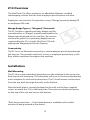
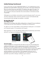
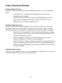
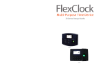
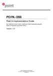
FlexClock® Z14
PROXIMITY VERSION
USER MANUAL & SETUP GUIDE
FLEXCLOCK SERIES
M U L T I - P U R P O S1E T I M E D E V I C E
Table of Contents
Installation and Setup Overview .................... Page 3
Z14 Overview.......................................................... Page 4
Installation................................................................ Page 4
Network Settings.................................................. Page 6
Initial Setup.............................................................. Page 6
Using the Z14.......................................................... Page 7
Troubleshooting.................................................... Page 7
Clock Dimensions
H: 5.5 in ; W: 6.5 in ; D: 1.5 in
2
Installation and Setup Overview
More details for each step can be found on the page number indicated.
Basic Installation Steps:
1. Find a suitable location for installation that is close
to both a power outlet and an Ethernet port
2. Unpack items from box
3. Mount device to the wall (Page 4)
4. Connect cables to device (Page 5)
5. Determine if any additional settings are required for
the network connection (Page 6)
6. Download device setting from server (Page 6)
7. Normal use (Page 7)
Z14 in Box
Z14 Installed
3
Z14 Overview
The FlexClock Z14 offers employers an affordable Ethernet- enabled
timekeeping solution that can track employee punch data in real-time.
Employees can record In/Out punches using a “Mango” proximity badge OR
an employee PIN code.
Mango Badge Type vs. “Wiegand” (Universal)
The Z14 utilizes a specific proximity badge card format referred to as “Mango,” typically indicated by the
Mango logo displayed on the card face. By contrast,
universal or generic-use proximity badges are not
supported by the Z14 (see the FlexClock Z18 with
appropriate Wiegand port for this feature).
Connectivity
The Z14 uses an Ethernet connection to send employee punch data through
the Internet. This provides real-time* access to employee punch data, as the
flow of data continues throughout the workday.
Installation
Wall Mounting
The Z14 has a removable back plate that must be attached to the unit as the
final step of wall mounting. This back plate will serve as the mounting bracket
and a template for wall anchor placement. The Z14 wall mount can be wired
from the top, back (through the wall), or the bottom.
After the back plate is securely fastened to the wall, use the four supplied
screws to attach the Z14 to the back plate. There are two attachment points
on the top of the unit and two on the bottom.
*Real-time connection — Punch data becomes available online within
minutes of being entered at the device.
4
Installation Continued
Connecting Z14
There are only two cables required to set up your new FlexClock Z14. An Ethernet
cable that connects to your network, and a power supply cable.
Follow the steps below to connect your Z14. For detailed network setup instructions, see page 6.
Ethernet Cable
Power Cable
Step-by-step instructions:
1. Find the supplied Ethernet cable
2. Insert one end of the Ethernet cable into
the Ethernet port on the wall and the other
end into the Ethernet port on the Z14
(shown in picture)
3. Find the supplied power adapter
Ethernet
4. Insert the power adapter into the wall
outlet (or surge protector) and the small
“barrel end” into the power port on the Z14
(shown in picture)
5. Once the clock has power, follow the
network setup steps on page 6
5
Power
Network Settings
Firewall Setup
Most firewalls will not need any additional setup, however, this device
requires specific open ports to connect to the Internet. These ports are
detailed below. If any connection issues arise, this is one likely cause. Notify
your firewall administrator that this device will need TCP ports 8288 and 8289
open. This device will make outgoing connections only and will not require
any inbound ports.
Network Setup
The FlexClock Z14 uses your company’s network to access the Internet. Most
networks will allow this device to connect automatically using a “dynamic” IP
address (DHCP). Your IT administrator can tell you if your network is DHCP
enabled or if you will need to set up a “static IP” address for this device. If any
connection issues arise, this is one likely cause.
Static IP Setup
Note: Only use these steps to setup a static IP address if your company’s network configuration requires it. To set up a static IP address you will need the
following information from your IT Administrator.
Static IP address:___________________________________________________
Subnet mask:_____________________________________________________
Default gateway:__________________________________________________
DNS server:_______________________________________________________
Alternate DNS server (optional):______________________________________
To access the Z14 network setup menu from the time and date screen: Press
the (*) key on the clock’s keypad; Type “2663”; Press (OK); Press (1); Press (2);
then follow the instructions on the screen and input each required IP address.
Initial Setup
When the clock has been connected to your network, press [9]. At this
time the settings for the clock will be retrieved from the server as long as your
account has been fully setup. These include: The current date and time, your
time zone, any Daylight Saving Time (DST) information, then any additional
needed settings.
6
Initial Setup Continued
If you receive the message “UNKNOWN SERIAL #,” your timekeeping service
provider may need to finish setting up your account. Once your account has
been set up on the server, wait about 10 minutes, then press (9) again. You
may want to check the clock’s internal serial number readout by pressing
the (*) button in the rare event that the serial number on the box has been
misprinted.
Although you can initiate a connection at any time by pressing (9), once your
clock has made the initial connection with the server it will automatically
transmit punch data and get any updates as needed.
Using the Z14
Clocking In & Out
When the Z14 records a time (often referred to as a “punch”) for an employee,
it will need to know if the employee is clocking in or clocking out.
To select “in” or “out,” (at the Main or Time and Date screen) press (1) to record
an “in” punch or press (2) to record an “out” punch.
After selecting (1) or (2) you will then either hold your proximity card in front
of the Z14 or input your employee PIN number.
PIN Entry
Proximity
Clock Prompts
Once an employee is recognized by the device, they may be prompted for
additional information (such as department #, job #, or tip amount). These
prompts are usually configured by your timekeeping service provider.
Optionally, the (4) and (5) keys can also be used to clock in and out, if enabled
on your account. This allows an alternate set of prompts to be shown to
certain employees, but not others. If the message “entry too short” is
displayed on the screen after an employee PIN is entered, your service
provider may need to change a setting on your account.
7
Troubleshooting
If any issues arise while installing, setting up, or using this device, please
contact your timekeeping service provider with the error message and/or
other details.
Network Connection
You can always force the time clock to attempt to contact the timekeeping
server at any time by pressing the (9) key.
The time clock’s ability to transmit depends on your Internet connection. If
you are having trouble transmitting, ensure your Internet connection is up.
You can unplug the clock’s power cable at any time and plug it back in to
force it to acquire a new IP address using Dynamic Host Control Protocol
(DHCP).
Daylight Saving Time
Your clock automatically adjusts for Daylight Saving Time (DST) as instructed
by the server. The adjustment takes place immediately when the clock
reaches the designated time (i.e. 2:00 a.m.) Adjustments occur on a Sunday.
From Sunday through Tuesday the clock will show a “DST checkmark” icon
next to the time, to remind employees that the DST correction has taken
place.
Error Message
If the message “entry too short” is displayed on the screen after an employee
PIN is entered, your service provider may need to change a setting on your
account.
Additional Questions
If you have any additional questions regarding the installation or use of your
clock, please contact your timekeeping service provider.
8
Z14 Keypad Replacement Steps
Needed Tools
Flat-head screwdriver
Philips-head screwdriver
Remove back cover
Pop the 3-pin and 4-pin connectors out by the Ethernet port (easiest done by
using a flat-head screwdriver)
Take out the four screws holding the back cover
Back cover pulls straight off
Disconnect keypad ribbon cable
This is the white and brown connector near the top edge of the main board.
Release the small brown bracket holding the cable in by sliding it up. The
cable should come free
Remove the keypad
This can be done with any fine-tipped tool (flat-head screwdriver recommended)
Carefully pry up one of the edges
There are three layers to the keypad (Outside keys, middle with metal brackets, bottom directly adhered to the clock casing)
The keypad is glued with a strong adhesive to the clock casing
While removing the keypad it may be a good idea to set the back cover back
on (without screws) to protect the insides while prying
Remove the main board
Remove the white 20-pin connector at the top right of the board
Remove the 2-pin connector that attaches to the speaker on the bottom of
the board
Take out the three screws holding it down
Flip the board to the left side to get it out of the way
Add new keypad
Take off the adhesive cover on the back of the new keypad
Line it up and stick it in the same crevice the old keypad was in
Make sure to get the ribbon cable through the slot in the top
Bend the ribbon cable up so that when you put the main board back in the
cable is accessible.
Continued next page . . .
9
Z14 Keypad Replacement Steps Continued
Replace the main board
Place it back in the same position (There are a few little black tabs by the left
and right screw holes that will match up) and screw it down
Connect cables again
Slide the ribbon cable back into the white connector with the brown bracket.
Tighten down the bracket
Reconnect the 2-pin speaker cable connector
Reconnect the 20-pin connector on the top right of the main board
Replace back cover
Be sure not to pinch any cables
Set correctly on top so the Ethernet, power and USB ports align with the
openings in the cover
Replace the 4 back cover screws
Replace the 3-pin and 4-pin connectors
10
Other FlexClock Models
The FlexClock Z-Series
Provides Ethernet connectivity and available biometrics at an unbeatable
value.
· FlexClock Z18 is a simple and affordable time clock using
a proximity card reader.
· FlexClock Z33 and Z34 are simple and affordable time clocks
with a built-in fingerprint reader. (They function the same,
differing only in style and appearance).
The FlexClock Vx-Series
Based on quality banking equipment from VeriFone®. All Vx-Series clocks
include a magstripe card reader, receipt printer, and fully support analog
dialup (landline) as an alternate communication method. Options include:
· FlexClock Vx510 and Vx570 - Basic model with Ethernet, Dialup,
and a printer. The Vx570 can be wall mounted while the Vx510 is
meant for tabletop use only.
· FlexClock Vx510G - Offers a cellular connection instead of
Ethernet. Requires AC power or vehicle power.
· FlexClock Vx610 - Offers a cellular connection instead of Ethernet,
and is completely portable with a built-in rechargeable battery.
Optional external fingerprint accessory available for all FlexClock
Vx-Series models.
Additional Questions
If you have any additional questions regarding the installation or use of your
FlexClock, please contact your service provider.
11
FlexClock Z14 Setup Guide
The company distributing this product does
not accept liability or responsibility for inaccurate
or missing information within this manual.
Any and all content within this document is
subject to change and may be updated at any
time without notice.
Copyright 2014
12
Printed in the USA 0601C