1
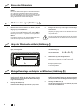
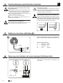
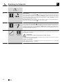
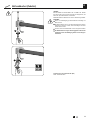
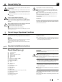
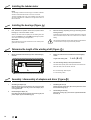
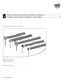
D
GB
Einbau- und Gebrauchsanleitung von Rademacher Rohrmotoren .......................................... 1
Installation and User Manual for Rademacher Tubular Motors ............................................... 14
Gültig für die Serien:/Valid for series: RTBS .../RTBM .../RTBL ...
Bitte notieren: / Please note: /
Montageort: / Installation location:
...............................................................................................................................
..
Seriennummer: / Serial number:
...............................................................................................................................
..
VBD 539-1-D-GB-(08.08)
D
Sehr geehrte Kunden...
...mit dem Kauf dieses Rohrmotors haben Sie sich für ein Qualitäts
produkt aus dem Hause Rademacher entschieden. Wir danken Ihnen
für Ihr Vertrauen.
CE-Zeichen und Konformität
Das vorliegende Produkt erfüllt die Anforderungen der geltenden
europäischen und nationalen Richtlinien.
Die Rademacher Rohrmotoren sind unter Aspekten des größten
Komforts entstanden. Mit einem kompromisslosen Qualitätsanspruch
und nach langen Versuchsreihen sind wir stolz, Ihnen dieses innovative
Produkt zu präsentieren.
Die Konformität wurde nachgewiesen, die entsprechenden Erklärungen
und Unterlagen sind beim Hersteller hinterlegt.
Dahinter stehen die hochqualifizierten
Mitarbeiterinnen und Mitarbeiter aus
dem Hause RADEMACHER.
Diese Anleitung...
...beschreibt Ihnen die Montage, den elektrischen Anschluss und
die Bedienung von Rademacher Rohrmotoren der Serien:
RTBS.../RTBM.../RTBL...
Bitte lesen Sie diese Anleitung vollständig durch und beachten Sie
alle Sicherheitshinweise, bevor Sie mit den Arbeiten beginnen.
Bitte bewahren Sie diese Anleitung auf und übergeben Sie die Anleitung bei einem Besitzerwechsel auch dem Nachbesitzer.
Bei Schäden, die durch Nichtbeachtung dieser Anleitung und der
Sicherheitshinweise entstehen, erlischt die Garantie. Für Folgeschäden, die daraus resultieren, übernehmen wir keine Haftung.
Zeichenerklärung
Lebensgefahr durch Stromschlag
Dieses Zeichen weist Sie auf Gefahren bei Arbeiten an elektrischen
Anschlüssen, Bauteilen etc. hin. Es fordert Sicherheitsmaßnahmen zum
Schutz von Gesundheit und Leben der betroffenen Person.
Hier geht es um Ihre Sicherheit.
Beachten und befolgen Sie bitte alle so gekennzeichneten Hinweise.
2
D
GB
STOP
So warnen wir vor Fehlverhalten, das zu Personen- oder Sachschäden führen kann.
HINWEIS/WICHTIG/ACHTUNG
Auf diese Weise machen wir Sie auf weitere, für die einwandfreie Funktion,
wichtige Inhalte aufmerksam.
Abbildungen / Illustrations
1
(2)
(1)
(3)
(4)
(5)
(7)
(6)
(8)
(9)
(10)
(11)
(12)
(13)
(14)
(15)
(17)
2
4
D
(18)
RTBS .../RTBM ...
3
RTBL ...
(19)
(7.3)
(8)
min.X
x
(16)
= (D/2)
L
(10)
B
C
A
(7.1)
(7.2)
L = A - (B + C)
5
(10)
(5)
(2)
(8)
(3)
(9)
(5)
(4)
6
8
7
RTBS .../RTBM ...
(1)
(4)
(5)
(5)
SW 50
SW 60
SW 70
(11)
(12)
(13)
(6)
(20)
(5)
SW 40
(14)
(20)
RTBL ...
(17)
(2)
3
D
GB
(6)
D
Allgemeine Sicherheitshinweise
Bei allen Arbeiten an elektrischen Anlagen besteht Lebensgefahr durch Stromschlag.
Bei unsachgemäßem Gebrauch besteht erhöhte Verletzungsgefahr.
Der Netzanschluss des Rohrmotors und alle Arbeiten an elektrischen Anlagen dürfen nur durch eine zugelassene Elektrofachkraft nach den Anschlussplänen in dieser Anleitung erfolgen
(s. Seite 8).
Unterweisen Sie alle Personen im sicheren Gebrauch des
Rohrmotors.
Den sich bewegenden Rollladen beobachten und Personen
fernhalten bis die Bewegung beendet ist.
Verbieten Sie Kindern mit ortsfesten Steuerungen oder der
Fernsteuerung zu spielen.
Bewahren Sie Handsender so auf, dass ein ungewollter Betrieb,
z. B. durch spielende Kinder, ausgeschlossen ist.
Führen Sie alle Reinigungsarbeiten am Rollladen im spannungslosen Zustand aus.
Führen Sie alle Montage- und Anschlussarbeiten im spannungslosen Zustand aus.
Bei Nichtbeachtung besteht Lebensgefahr!
Vorschriften bei Installation in Feuchträumen beachten.
Beachten Sie besonders beim Einsatz in Feuchträumen die DIN
VDE 0100, Teil 701 und 702. Diese Vorschriften enthalten zwingende Schutzmaßnahmen.
Der Einsatz defekter Geräte kann zur Gefährdung von Personen und zu Sachschäden führen (Stromschlag, Kurzschluss)
Verwenden Sie niemals defekte oder beschädigte Geräte.
Prüfen Sie Antrieb und Netzkabel auf Unversehrtheit.
WICHTIG
Nach der Norm DIN EN 13695 muss dafür Sorge getragen werden,
dass die für die Behänge festgelegten Verschiebebedingungen nach
EN 12045 eingehalten werden. Dabei ist besonders darauf zu achten,
dass die Ausfahrgeschwindigkeit des Behanges auf den letzten 0,4 m
kleiner als 0,2 m/s sein muss.
Wenden Sie sich bitte an unseren Service (s. letzte Seite), falls
Sie Schäden am Gerät feststellen.
Richtige Verwendung / Einsatzbedingungen
Verwenden Sie die Rohrmotoren nur zum Öffnen und Schließen
von Rollläden und Markisen.
WICHTIG
Das Motorkabel muss innenliegend im Leerrohr, unter Beachtung der örtlichen Elektrovorschriften, bis zur Abzweigdose
verlegt werden.
Verwenden Sie nur Original-Bauteile und -Zubehör des Herstellers.
Einsatzbedingungen
Für den elektrischen Anschluss muss am Einbauort ständig ein
230 V /50 Hz Stromanschluss, mit bauseitiger Freischaltvorrichtung (Sicherung), vorhanden sein.
Wichtige Montagehinweise
Gesamtansicht (Abbildung 1 )
4
(1)
(2)
(3)
(4)
(5)
(6)
(7.1)
(7.2)
(7.3)
(8)
(9)
(10)
( 11 )
(12)
(13)
(14)
(15)
(16)
(17)
(18)
(19)
(20)
Gegenlager
Kugellager
Achsstift der Walzenkapsel
Walzenkapsel
Wickelwelle
Befestigungsfeder
Sicherungsclip (RTBS.../RTBM...)
Sicherungsring (RTBL...)
Paßfeder (RTBL...)
Mitnehmer
Rohrmotor
Adapter
2 Einstellschrauben
Antriebskopf
Antriebslager
Halteklammer
Motorkabel
Optional erhältlich: Steuerung (z.B. Troll C50)
Rollladenpanzer
Limitring
Getriebeabtriebswelle
Einhängeklammer
D
GB
WICHTIG
Vergleichen Sie vor der Montage die Angaben zur Spannung/
Frequenz auf dem Typenschild mit denen des örtlichen Netzes.
Vor dem Einbau des Rohrmotors, alle nicht zum Betrieb benötigten
Leitungen und Einrichtungen abbauen bzw. außer Betrieb setzen.
Bewegliche Teile von Antrieben, die unter einer Höhe von 2,5 m
vom Boden betrieben werden, müssen geschützt werden.
Wird der Rohrmotor mit einem Schalter mit AUS-Voreinstellung
gesteuert, ist dieser Schalter in Sichtweite des Rohrmotors anzubringen, aber von sich bewegenden Teilen entfernt, in mindestens
1,5 m Höhe.
Die Wickelwelle unbedingt waagerecht montieren!
Bei schiefer Aufwicklung des Rollladens können Schäden am
Motor oder am Rollladen entstehen.
Der Deckel des Rollladenkastens muss leicht zugänglich und
abnehmbar sein.
Vergleichen Sie nach dem Auspacken:
den Packungsinhalt mit den Angaben zum Lieferumfang auf der
Verpackung.
den Motortyp mit den entsprechenden Angaben auf dem Typenschild.
D
GB
Inhalt/Contents
D
Sicherheitshinweise ...................................................................4
Wichtige Montagehinweise .........................................................4
Einbau des Rohrmotors ..............................................................6
Montieren der Lager ...................................................................6
Einbau des Motors in die Lager ..................................................7
Sicherheitshinweise elektrischer Anschluss ................................8
Elektrischer Anschluss ................................................................8
Steuerung eines Antriebes/einpol. Rollladenschalter ...................8
Einstellung der Endpunkte ........................................................9
Montage des Rollladenpanzers ..................................................9
Probelauf/Verändern der Endpunkte .........................................10
Nothandkurbel ..........................................................................11
Was tun, wenn... ? ....................................................................12
Technische Daten .....................................................................13
Garantiebedingungen ...............................................................24
GB
Safety instructions ......................................................................15
Important installation instructions.................................................15
Installing the tubular motor ..........................................................16
Mounting the bearings ................................................................16
Installing the motor in the bearings ..............................................17
Safety instructions for electrical connection ..................................18
Electrical connection ...................................................................18
Controlling a drive / single-pole roller blind switch .........................18
Adjusting the end stops ...............................................................19
Installation of the roller shutter curtain..........................................19
Test run / changing the end stops ................................................20
Emergency hand crank...............................................................21
What to do if ... ?........................................................................22
Technical data ............................................................................23
Warranty conditions ....................................................................24
D
GB
5
D
Einbau des Rohrmotors
HINWEIS
Die folgenden Einbauhinweise gelten für Standardeinbausituationen in Verbindung mit Rademacher-Rohrmotoren und -Zubehör.
Der Antriebskopf (12) des Motors kann auf der rechten oder der
linken Seite des Rollladenkastens eingebaut werden. In dieser Anleitung ist der Einbau für die rechte Seite dargestellt.
Montieren der Lager (Abbildung 2 )
1.
Bestimmen Sie zuerst die Position von Antriebs- (13) und
Gegenlager (1) im Rollladenkasten.
2.
Befestigen Sie die Lager je nach Lagertyp und bauseitigen
Gegebenheiten.
Wickeln Sie den Rollladenpanzer vollständig auf die Wickelwelle
und messen Sie den Durchmesser D. Siehe Abbildung 2 zur
Bestimmung der Position der Lagermitte zur Führungsschiene.
Montieren Sie das Antriebslager (13) so, dass die Einstellschrauben
(11) später gut zugänglich sind und das Motorkabel ohne Knick
verlegt werden kann.
WICHTIG
Im eingebauten Zustand muss der aufgewickelte Rollladen senkrecht in die Führungsschiene des Fensters einlaufen.
Achten Sie auf den waagerechten Einbau der Lager. Ein schief auf
gewickelter Rollladen kann den Antrieb blockieren und zerstören.
Länge der Wickelwelle ermitteln (Abbildung 3 )
1.
Messen Sie den Wandabstand von Antriebs- (13) und Gegenlager (1) wie dargestellt.
2.
Messen Sie den Rollladenkasten aus und ermitteln Sie die
nötige Wellenlänge (L).
Länge der Wickelwelle:
L = A - (B + C)
L
3.
Die Wickelwelle (5) auf das nötige Maß kürzen.
Sägen Sie die Welle mit einer Eisensäge rechtwinklig auf Maß.
Entgraten Sie die Welle innen und außen mit einer Feile.
B
A
C
B = Gegenlager/Walzenkapsel
C = Antriebslager/Motor
Montage/Demontage von Adapter und Mitnehmer (Abbildung 4 )
1.
Montage des Adapters (10)
1.
Schieben Sie den Adapter (10) über den Limitring (18) am
Antriebskopf bis er einrastet. Achten Sie dabei auf die richtige
Lage der Nut im Adapter (10).
2.
Demontage des Adapters (10)
Drücken Sie beide Haltefedern am Limitring (18) nach unten
und ziehen Sie den Adapter (10) vom Limitring (18) ab.
6
D
GB
Montage des Mitnehmers (8)
Schieben Sie den Mitnehmer (8) bis zum Anschlag auf die Achse
(19) und sichern Sie ihn mit dem beiliegenden Sicherungsclip (7)
2.
Demontage des Mitnehmers (8)
Lösen Sie den Sicherungsclip (7) von der Achse (19) und demontieren Sie den Mitnehmer (8).
D
Rohrmotor in die Wickelwelle schieben (Abbildung 5 )
STOP
Schlagen Sie nie den Motor (9)
mit Gewalt in die Wickelwelle (5)
ein.
Das führt zu seiner Zerstörung.
1.
Schieben Sie zuerst den Mitnehmer (8) in die Wickelwelle (5).
2.
Drücken Sie danach die Wickelwelle (5) vollständig auf den
Adapter (10).
WICHTIG
Achten Sie darauf, dass der Adapter (10) während der Montage nicht
vom Limitring (18) am Antriebskopf (12) abrutscht, es kommt sonst
zu Fehlfunktionen, s. Seite 12.
WICHTIG
Bei Wickelwellen mit innenliegender Falz muss der Motor (9) ausreichend Freiraum haben.
Einstecken der Walzenkapsel (Abbildung 5 )
1.
Schieben Sie die Walzenkapsel (4) in die Wickelwelle (5)
und stecken Sie anschließend das Kugellager (2) auf den
Achsstift (3).
Einbau des Motors in die Lager (Abbildung 6 )
1.
Antriebslager (13) - als Klicklager
2.
Gegenlager (1)
Drücken Sie den Antriebskopf (12) leicht in das Antriebslager
(13), bis er eingerastet ist.
Stecken Sie das andere Ende der Wickelwelle (5) mit dem
Kugellager (2) in das Gegenlager (1).
HINWEIS
Die Einstellschrauben (11) müssen gut zugänglich sein.
Falls Sie ein anderes Antriebslager als das Rademacher-Klicklager verwenden, müssen Sie jetzt ggf. den Antrieb mit einem
zweiten Splint sichern.
Die Rohrmotoren können in 4 Stellungen in das Klicklager (13) eingebaut werden. Durch Spreizen der Halteklammer (14) können
Sie die Motoren jederzeit wieder aus dem Klicklager (13) lösen.
Antriebslager (13) - alle anderen Lagervarianten
Stecken Sie den Antriebskopf (12) an das jeweilige Antriebslager und sichern Sie ihn entsprechend, z.B. mit einem Splint.
3.
Korrigieren Sie leichte Maßungenauigkeiten durch Einschieben oder Herausziehen der Walzenkapsel (4).
WICHTIG
Sichern Sie die Walzenkapsel (4) zum Schluss mit einer
Schraube.
Die Walzenkapsel (4) muss mindestens mit 2/3 ihrer Länge
in der Wickelwelle (5) stecken.
D
GB
7
D
Sicherheitshinweise zum Elektrischen Anschluss
Bei allen Arbeiten an elektrischen Anlagen besteht Lebensgefahr durch Stromschlag.
Bei festinstallierten Geräten...
...muss gemäß DIN VDE 0700, installationsseitig eine Trennvorrichtung für jede Phase vorhanden sein. Als Trennvorrichtung gelten Schalter mit einer Kontaktöffnungsweite von min. 3 mm (z. B.
LS-Schalter, Sicherungen od. FI-Schalter).
Der Netzanschluss des Rohrmotors und alle Arbeiten an elektrischen Anlagen dürfen nur durch eine zugelassene Elektrofachkraft nach den Anschlussplänen in dieser Anleitung erfolgen.
Trennen Sie die Zuleitung allpolig vom Netz und sichern Sie sie
gegen unbeabsichtigtes Einschalten.
Kurzschlussgefahr durch Wasser bei falscher Kabelführung.
Prüfen Sie die Anlage auf Spannungsfreiheit.
Verlegen Sie das Motorkabel (15) nie direkt senkrecht nach oben,
sonst kann evtl. Wasser über das Kabel in den Motor laufen und
diesen zerstören. Verlegen Sie das Kabel in einer Schlaufe. Die
Schlaufe bewirkt, dass am Kabel ablaufendes Wasser am tiefsten
Punkt der Schlaufe gesammelt wird und dort abtropft.
Führen Sie alle Montage- und Anschlussarbeiten nur im
spannungslosen Zustand aus.
Kurzschlussgefahr durch beschädigte Kabel.
Verlegen Sie alle Kabel im Rollladenkasten so, dass diese nicht
durch bewegliche Teile beschädigt werden können.
STOP
Elektrischer Anschluss (Abbildung 9 )
9
1.
Führen Sie das Motorkabel (15) nach dem Einhängen des
Motors in die dafür vorgesehene Abzweig- oder Schalterdose.
Farbskala der Motorleitung (15)
(15)
L1 ( / )
L1
L1
N
PE
=
=
=
=
Drehrichtung 1
Drehrichtung 2
Neutralleiter
Erdung
(schwarz)
(braun)
(blau)
(grün/gelb)
L1 ( / )
N
PE
Steuerung eines Antriebes mit einem einpoligen Rollladenschalter
Installationsplan und Anschlussplan für die Montage an der
rechten Seite.
Steuergerät
z.B. 1poliger
Schalter/Taster
8
D
GB
blau
schwarz
L1
N
PE
grün / gelb
Schalterdose
3
NETZ
230 V/50 Hz
braun
grün/ gelb
4
blau
M
schwarz
M
D
Einstellung der Endpunkte
1.
HINWEIS
Führen Sie vorab einen Probelauf des Motors durch, ohne das der Rollladenpanzer eingehängt ist.
Lassen Sie den Motor (über eine Zeitschaltuhr oder einen Schalter), in Richtung Tieflauf ( ) laufen,
bis dieser selbstständig abschaltet. Vergewissern Sie sich bitte, dass dies die tatsächliche
Abwärtsrichtung, also Tieflauf ( ) für Ihren Rollladen ist!
Hat der Rollladenmotor die falsche Laufrichtung (Laufrichtung des Motors stimmt nicht mit der Schalterposition für Hochlauf ( ) und Tieflauf ( ) überein), vertauschen Sie die braune und die schwarze Ader
in der Abzweig- oder Schalterdose.
Setzen Sie jetzt den Motor weiter in Laufrichtung Tieflauf ( ) in Betrieb, bis die untere Endabschaltung erfolgt.
Montage des Rollladenpanzers (Abbildung 7 / 8 )
Montieren Sie den Rollladenpanzer (17) mit Befestigungsfedern (6) (Zubehör) an der Wickelwelle (5).
2.
STOP
Nie im Bereich des Antriebs bohren
oder schrauben um den Rollladen
zu befestigen.
WICHTIG Nur wenn der Motor in der Wickelwelle montiert ist,
funktioniert die Endabschaltung.
a. Schieben Sie die Befestigungsfedern (6) auf die oberste Lamelle des Rollladenpanzers (17).
b. Setzen Sie alle 40 cm eine Befestigungsfeder (6) in die rechteckigen Löcher der Wickelwelle (5).
c. Verwenden Sie bei Wickelwellen SW 40 (mit Außenfalz) Einhängeklammern (20) zur Montage der
Befestigungsfedern (6); siehe Abbildung 8 .
WICHTIG
Die Endpunkte für oben und unten werden mit 2 Einstellschrauben eingestellt. Verwenden Sie dazu das
beiliegende Einstellwerkzeug, um die Schrauben zu drehen.
3.
Endpunkteinstellung
Einstellschrauben
*
= Tieflauf
Einstellwerkzeug
= Hochlauf
= Verlängerung
des jeweiligen Laufweges
= Verkürzung
des jeweiligen Laufweges
Bei Rechts-/ oder Linkseinbau: Mit der Einstellschraube am nach oben zeigenden Pfeil wird der untere
Endpunkt eingestellt. Mit der Einstellschraube am nach unten zeigenden Pfeil wird der obere Endpunkt
eingestellt.
Drehen in Richtung + (Plus) bewirkt die Verlängerung des Laufweges.
Umgekehrtes Drehen bewirkt eine Verkürzung.
für die Plus- und Minusrichtung kann modellabhängig variieren.
* Drehsinn
Achten Sie auf die Bedruckung am Motorkopf!
D
GB
9
D
Einstellung der Endpunkte
4.
Oberer Endpunkt
Fahren Sie den Motor in den Hochlauf ( ). Drehen Sie vorsichtig die entsprechende Einstellschraube
mit dem beiliegenden Einstellwerkzeug in minus (-) Richtung bis der Motor abschaltet. Lassen Sie die
Zeitschaltuhr oder den Schalter in der Schalterposition "Hochlauf" stehen und drehen Sie vorsichtig die
entsprechende Einstellschraube mit dem beiliegenden Einstellwerkzeug in plus (+) Richtung bis der Motor
den gewünschten Endpunkt erreicht hat.
Sicherheitshinweis: Es können Temperaturunterschiede (Winter - Sommer) auf den Rollladenpanzer einwirken. Daher die Endlage für Hochlauf ( ) mit 2-3 cm “Luft” einstellen
5.
Unterer Endpunkt (Nachjustierung)
Fahren Sie den Motor in den Tieflauf ( ). Drehen Sie vorsichtig die entsprechende Einstellschraube mit
dem beiliegenden Einstellwerkzeug in minus (-) Richtung bis der Motor abschaltet. Lassen Sie die Zeitschaltuhr oder den Schalter in der Schalterposition "Tieflauf" stehen und drehen Sie vorsichtig die entsprechende Einstellschraube mit dem beiliegenden Einstellwerkzeug in plus (+) Richtung bis der Motor
den gewünschten Endpunkt erreicht hat.
6.
Probelauf / Verändern der Endpunkte
Kontrollieren Sie Ihre Einstellungen und lassen Sie den Rollladen in beide Richtungen laufen, bis die Endpunkte den Motor ausschalten.
Thermoschutz
Die Rohrmotoren sind für den Kurzzeitbetrieb (ca. 4 Min.) ausgelegt.
Das Überschreiten dieser Zeit oder häufiges Umschalten führen zur Erwärmung. Lassen Sie den Motor
in diesem Fall ca. 20 Minuten abkühlen.
Verändern der Endpunkte
Fahren Sie den Rollladen in die Mittelstellung zurück und beginnen Sie von vorn. Siehe Bild
Endpunkteinstellung (Pos.3) auf Seite 9.
10
D
GB
D
Nothandkurbel (Zubehör)
HINWEIS
Bei den Modellen der Serien RTBM...HK.. und RTBL...HK.. besteht
bei Stromausfall oder Funktionsstörungen die Möglichkeit, den
Rohrmotor per Nothandkurbel zur betreiben.
Die Nothandkurbel ist Zubehör und nicht im Lieferumfang enthalten.
ACHTUNG:
Motor vor der Betätigung per Nothandkurbel unbedingt vom
Netz trennen!
Die Nothandkurbel darf nur bei Stromausfall bedient werden,
außerdem ist darauf zu achten, dass die Endlagen nicht überfahren werden dürfen.
Personen sind beim Handbetrieb von der Anlage fernzuhalten.
a
Die Nothandkurbel ist wegen Verletzungsgefahr oder Sachbeschädigung sofort nach Betätigung wieder aus der Anlage zu
entnehmen.
b
Ausführungen mit Nothandkurbel (HK)
Siehe: Technische Daten
D
GB
11
D
Was tun, wenn...?
Der Antrieb hebt bzw. senkt die Rolllade nicht, startet zu
langsam oder mit lauten Geräuschen.
...der Rohrmotor im Normalbetrieb zwischen beiden Endpunkten stehen bleibt?
Mögliche Ursache 1:
Die Anschlüsse sind nicht korrekt.
Mögliche Ursache:
Der Thermoschutz hat angesprochen.
Lösung 1:
Überprüfen der Anschlüsse.
Lösung:
Den Motor ca. 20 Minuten abkühlen lassen.
Mögliche Ursache 2:
Falsche Installation oder Überlastung.
Lösung 2:
Überprüfen der Installation und Rollladenlast.
...der Rollladen im Hochlauf stehen bleibt?
...der Rollladen stoppt während des Hebens oder Senkens?
Lösung:
Vereisung bzw. Hindernis beseitigen.
Mögliche Ursache 1:
Erreichen des eingestellten Endpunktes.
Lösung 1:
Endpunkte erneut nach Anleitung setzen.
Mögliche Ursache 2:
Betriebsdauer überschritten (4 Min.).
Lösung 2:
Lassen Sie den Rohrmotor ca. 20 Minuten abkühlen.
...der Motor nicht läuft?
Mögliche Ursache:
Die Netzspannung fehlt.
Lösung:
Prüfen Sie mit einem Spannungsmessgerät ob die Versorgungsspannung (230 V) anliegt und überprüfen Sie die Verdrahtung.
Beachten Sie besonders die Angaben zu den unzulässigen Anschlussarten.
Überprüfen der Installation.
...die Drehrichtung falsch ist?
Mögliche Ursache:
Die Steuerleitungen sind vertauscht.
Lösung:
Trennen Sie die Zuleitung vom Netz und vertauschen Sie die
schwarze/braune Ader des Motorkabels an Ihrer Steuerung.
...der Rohrmotor bei Einstellarbeiten und Probelauf nicht
stoppt?
Mögliche Ursache 1:
Der Adapter (10) ist möglicherweise vom Limitring (18) am
Antriebskopf (12) abgerutscht.
Lösung 1:
Prüfen Sie, ob der Adapter (10) bündig vor dem Antriebskopf (12)
sitzt und vollständig in der Wickelwelle (5) steckt.
Schieben Sie den Adapter (10) wieder bündig vor den Antriebskopf (12) und schieben Sie die Wickelwelle (5) vollständig
auf den Adapter (10), s. Abbildung 5 . Stellen Sie ggf. die Endpunkte neu ein, s. Seite 9.
Mögliche Ursache 2:
Walzenkapsel nicht fixiert oder Rollladenwelle zu kurz.
Lösung 2:
Walzenkapsel fixieren oder passende Rollladenwelle einsetzen.
12
D
GB
Mögliche Ursache:
Vereister Rollladen bzw. Hindernis in der Laufschiene.
Rollladen in Abwärtsrichtung freifahren.
D
Technische Daten
Motorserie
Typ:
RTBS ...
6/28
6
28
230
50
121
0,53
4
4
0,75
2,5
30
H
I
IP 44
*
472
35
2
Motorserie
Typ:
RTBM ...
10/16 10/16 20/16 20/16 30/16 30/16 40/16 40/16 50/12 50/12
HK
HK
HK
HK
10
10
20
20
30
30
40
40
50
50 [Nm]
16
16
16
16
16
16
12
12 [U/min]
16
16
230
230
230
230
230
230
230
230
230
230 [V]
50
50
50
50
50
50
50
50
50
50 [Hz]
121
112
145
145
191
191
198
198
205
205 [W]
0,53 0,49 0,64 0,64 0,83 0,83 0,86 0,86 0,89 0,89 [A]
[Min.]
4
4
4
4
4
4
4
4
4
4
4
4
4
4
4
4
4
4
4
4
0,75 0,75 0,75 0,75 0,75 0,75 0,75 0,75 0,75 0,75 [mm2 ]
2,5
2,5
2,5
2,5
2,5
2,5
2,5
2,5
2,5
2,5 [m]
30
22
22
22
22
22
22
22
22
22 [U]
H
H
H
H
H
H
H
H
H
H
I
I
I
I
I
I
I
I
I
I
IP 44 IP 44 IP 44 IP 44 IP 44 IP 44 IP 44 IP 44 IP 44 IP 44
*
*
*
*
*
*
*
*
*
*
472
474
474
574
544
624
544
624
544
624 [mm]
35
45
45
45
45
45
45
45 [mm]
45
45
2
2
2
2
2
2
2
2
2
2
HK = mit Notkurbel
Nenndrehmoment:
Leerlaufdrehzahl:
Nennspannung:
Frequenz:
Nennleistung:
Stromaufnahme:
Einschaltdauer (KB):
Anzahl der Adern:
Aderquerschnitt:
Kabellänge (Standard):
Endschalterbereich: (Anzahl d. Umdreh.)
Isolationsklasse:
Schutzklasse:
Schutzart n. VDE 700:
Leitungsart: (* = Gummi)
Motorlänge ohne Lager:
Rohrdurchmesser:
Anzahl parallel schaltbarer Rohrmotore
(Bei Verwendung der
Rademacher Steuerung, z.B. Troll C50)
RTBL ...
60/15 60/15 80/15 80/15 100/12 100/12
HK
HK
HK
60
60
80
80
100
100
15
15
15
15
12
12
230
230
230
230
230
230
50
50
50
50
50
50
272
272
298
298
305
305
1,26 1,26 1,34 1,34 1,36 1,36
4
4
4
4
4
4
4
4
4
4
4
4
0,75 0,75 0,75 0,75 0,75 0,75
2,5
2,5
2,5
2,5
2,5
2,5
22
22
22
22
22
22
H
H
H
H
H
H
I
I
I
I
I
I
IP 44 IP 44 IP 44 IP 44 IP 44 IP 44
*
*
*
*
*
*
658
658
658
658
658
658
60
60
60
60
60
60
2
2
2
2
2
2
120/9 120/9
HK
120
120
9
9
230
230
50
50
305
305
1,36 1,36
4
4
4
4
0,75 0,75
2,5
2,5
22
22
H
H
I
I
IP 44 IP 44
*
*
658
658
60
60
2
2
[Nm]
[U/min]
[V]
[Hz]
[W]
[A]
[Min.]
[mm2 ]
[m]
[U]
[mm]
[mm]
HK = mit Notkurbel
Nenndrehmoment:
Leerlaufdrehzahl:
Nennspannung:
Frequenz:
Nennleistung:
Stromaufnahme:
Einschaltdauer (KB):
Anzahl der Adern:
Aderquerschnitt:
Kabellänge (Standard):
Endschalterbereich: (Anzahl d. Umdreh.)
Isolationsklasse:
Schutzklasse:
Schutzart n. VDE 700:
Leitungsart: (* = Gummi)
Motorlänge ohne Lager:
Rohrdurchmesser:
Anzahl parallel schaltbarer Rohrmotore
(Bei Verwendung der
Rademacher Steuerung, z.B. Troll C50)
D
GB
13
GB
Dear Customers,
...By purchasing this tubular motor, you have chosen a quality pro
duct from the house of Rademacher. We would like to thank you for
your confidence.
CE Mark and Conformity
The present product complies with the requirements of the current
European and national directives.
Rademacher tubular motors have been developed for maximum
convenience. With an uncompromising demand for quality, and after
many series of tests, we are proud to present this innovative
product.
The conformity has been proved and the corresponding declarations
and documentation are available on file at the manufacturer’s premises.
The highly qualified employees
of the house of RADEMACHER
stand behind it.
These instructions...
...describe the installation, electrical connection, and operation of
Rademacher Tubular Motors of the series:
RTBS.../RTBM.../RTBL...
Before you begin work, please read these instructions through completely and follow all the safety instructions.
Please save these instructions in a safe place and give them to any
future owners.
Damage resulting from non-compliance with these instructions and
safety instructions will void the guarantee. We assume no liability
for any consequential damage.
Key to Symbols
Danger of fatal electric shock
This symbol warns of hazards when working with electrical connections, components, etc. It requires safety measures to protect the
health and life of the affected person.
This concerns your safety.
Please pay particular attention and carefully follow all instructions
marked with this symbol.
14
D
GB
STOP
This symbol warns of malpractices that can result in personal
injury or property damage.
NOTE/IMPORTANT/CAUTION
This is to draw your attention to information that is important for,
trouble-free operation.
GB
General Safety Tips
For any work on electrical systems, there is a risk to life due
to electrocution.
Inappropriate use causes increased risk of injury.
Instruct everyone about the safe operation of the tubular motor.
Only a certified electrician may connect the tubular motor to the
power connection, or do any work on electrical systems, and
only in accordance with the connection diagram in these instructions (see Page 18).
Observe the moving shades, and keep people away until the
motion is completed.
Do not allow children to play with installed or remote controls.
Perform any installation and connection work with the power
disconnected.
Store the hand transmitter such that undesired operation, such
as by playing children, is impossible.
Perform any cleaning tasks on the roller blind with the power
disconnected.
Failure to comply constitutes a hazard to life.
Follow the regulations when installing in damp locations.
For use in damp locations, take particular note of DIN VDE 0100,
Part 701 and 702. These regulations contain mandatory protection
measures.
IMPORTANT
According to the DIN EN 13695 standard, care must be taken that
the curtain moving conditions according to EN 12045 are met. Special
care must be taken that the travel speed of the curtain must be less
than 0.2 m/s for the last 0.4 m.
The use of defective devices can lead to hazards to persons and
equipment damage (electrocution, short circuits)
Never use defective or damaged devices.
Check the drive and power cord for intactness.
Please contact our Service Group (see last page) if you find
damage to the device.
Correct Usage / Operational Conditions
Use the tubular motors only to open and close roller blinds and
awnings.
IMPORTANT
The motor cable must be run inside the empty tube, in compliance
with the local electrical codes, to the junction box.
Use only original components and accessories from the manufacturer.
Operational Conditions
For the electrical connection, a 230 V/50 Hz power drop must be
continuously available at the installation site, with a disconnect
device (cut-out) provided by the customer.
Important installation instructions
Overall View (Figure 1 )
(1)
(2)
(3)
(4)
(5)
(6)
(7.1)
(7.2)
(7.3)
(8)
(9)
(10)
( 11 )
(12)
(13)
(14)
(15)
(16)
(17)
(18)
(19)
(20)
Counter bearing
Ball bearing
Axle pin on the roller capsule
Roller capsule
Winding shaft
Tie
Securing clip (RTBS.../RTBM...)
Securing ring (RTBL...)
Feather key (RTBL...)
Driver
Tubular motor
Adapter
2 Adjustment screws
Drive head
Drive bearing
Bracket
Motor cable
Optionally available: Controller (e.g. Troll C50)
Roller shutter curtain
Limit ring
Gearbox output shaft
Hanging brackets
IMPORTANT
Before installation, compare the voltage/frequency data on the rating
plate with those of the local grid.
Prior to installing the tubular motor, remove or disable any cables
and devices not needed for operation.
Moving parts on drives that are operated at a height of less than
2.5 m must be guarded.
If the tubular motor is controlled by a switch with an OFF preset,
this switch is to be mounted within line of sight of the tubular motor,
but away from moving parts, at a height of at least 1.5 m.
Always mount the winding shaft horizontally.
If the roller blind is crooked when rolled up, the motor or the roller
blind may be damaged.
The cover of the roller blind box must be easily accessible and
removable.
After unpacking, compare:
the package contents with the information on the scope of delivery
in the package.
the motor model with the corresponding information on the
rating plate.
D
GB
15
GB
Installing the tubular motor
NOTE
The following installation instruction apply to standard installation
situations for Rademacher tubular motors and accessories.
The drive head (12) of the motor can be installed on the right or left
side of the roller blind box. Installation on the right side is shown in
these instructions.
Installing the bearings (Figure 2 )
1.
First, determine the position of the drive (13) and counter
bearings (1) in the roller shutter curtain.
2.
Mount the bearing, depending on the type of bearing and the
building situation.
Wind the roller blind shield completely onto the winding shaft, and
measure the diameter D. See Figure 2 for determining the position
of the centre of the bearing on the guide track.
Assemble the drive bearing (13) such that the adjustment screws (11)
will be accessible later, and the motor cable can be run without
kinking.
IMPORTANT
When installed, the wound-up roller blind must run vertically in the
guide track on the window.
Take care that the bearings are level when installed. A roller blind that
is crooked when wound up can jam and destroy the drive.
Determine the length of the winding shaft (Figure 3 )
1.
Measure the distance from the drive (13) to the counter bearing (1),
as shown.
2.
Measure the roller blind box and determine the shaft length (L)
needed.
Length of the winding shaft:
L = A - (B + C)
L
3.
Cut off the winding shaft (5) to the required dimension.
Saw off the shaft squarely with a metal saw to the correct dimension.
Deburr the shaft, inside and outside, with a file.
B
A
C
B = Counter bearing / Roller capsule
C = Drive bearing / Motor
Assembly / disassembly of adapters and driver (Figure 4 )
1.
Assembling the adapter (10)
1.
2.
Disassembling the adapter (10)
Press down on both retaining springs on the limit ring (18) and
pull the adapter (10) off of the limit ring (18).
16
D
GB
Assembling the driver (8)
Slide the driver (8) onto the axle (19) to the stop and secure it with
the included securing clip (7).
Slide the adapter (10) over the limit ring (18) on the drive head
until it engages. Make sure the groove in the adapter (10) is
correctly positioned.
2.
Disassembling the driver (8)
Remove the securing clip (7) from the axle (19) and disassemble
the driver (8).
GB
Slide the tubular motor into the winding shaft (Figure 5 )
STOP
Never strike the motor (9) violently
to insert it in the winding shaft (5).
This will destroy it.
1.
First slide the driver (8) into the winding shaft (5).
2.
Next, press the winding shaft (5) completely onto the adapter (10).
IMPORTANT
Take care that the adapter (10) does not slide off of the limit ring (18)
on the drive head (12) during assembly, or a malfunction will occur;
see Page 22.
IMPORTANT
For winding shaft with interior seams, the motor (9) must have
sufficient clearance.
Inserting the roller capsule (Figure 5 )
1.
Slide the roller capsule (4) into the winding shaft (5), then place
the ball bearing (2) on the axle pin (3).
Installing the motor in the bearings (Figure 6 )
1.
Drive bearing (13) - as a click bearing
2.
Counter bearing (1)
Press the drive head (12) lightly into the drive bearing (13) until
it engages.
Insert the other end of the winding shaft (5) with the ball bearing (2)
into the counter bearing (1).
NOTE
The adjustment screws (11) must be accessible.
If you are using a different drive bearing than the Rademacher
click bearing, you may now need to secure the drive with another
splint.
The tubular motors can be installed in the click bearing (13) in 4positions. By spreading the bracket (14), you can remove the motors
from the click bearing (13) again at any time.
Drive bearing (13) - all other bearing variants
Place the drive head (12) on the drive bearing and secure it appropriately, such as with a splint.
3.
Correct for slight dimensional accuracies by sliding the roller
capsule (4) in or out.
IMPORTANT
Secure the roller capsule (4) with a screw afterward.
The roller capsule (4) must have at least 2/3 of its length inserted
into the winding shaft (5).
GB NL
D
GB
17
GB
Safety instructions for electrical connection
For any work on electrical systems, there is a risk to life due
to electrocution.
For fixed installation devices...
...A disconnect must be present for each phase on the installation
side, according to DIN VDE 0700. Switches with a contact opening
width of at least 3 mm (e.g., circuit breakers, fuses, or residual
current devices).
Only a certified electrician may connect the tubular motor to the
power connection, or do any work on electrical systems, and only
in accordance with the connection diagram in these instructions.
Disconnect the feed from the grid on all poles, and secure it
against unintended connection.
Short circuit hazard due to water if cables are improperly routed.
Test the system for zero voltage.
Never route the motor cable (15) directly vertically, or water may
run down the cable into the motor and destroy it. Route the cable
in a loop. The loop ensures that water running down the cable is
collected at the lowest point and drips from there.
Perform any installation and connection work only with the power
disconnected.
Damaged cables present a short circuit hazard.
Run all cables in the roller blind box, such that they cannot be
damaged by moving parts.
STOP
Electrical connection (Figure 9 )
9
1.
Run the motor cable (15), after mounting the motor, in the
junction box or switch box provided for it.
Color codes for motor conductors (15)
(15)
L1 ( / )
L1
L1
N
PE
=
=
=
=
Rotational direction 1
Rotational direction 2
Neutral line
Ground
(black)
(brown)
(blue)
(green/yellow)
L1 ( / )
N
PE
Controlling a drive with a single-pole roller blind switch
Installation layout and connection diagram for mounting on the
right side.
M
Control device
e.g., single-pole
switch/button
18
D
GB
blue
blue
black
L1
N
PE
green/yellow
Switch unit
3
GRID
230 V/50 Hz
brown
4
black
green/yellow
M
GB
Adjusting the end stops
1.
NOTE
Perform a test run on the motor first, without the roller shutter curtain in place. Let the motor run
(using a time switch or a switch) in the down ( ) direction until it shuts off by itself. Please ensure
that this is the correct downward direction, or down ( ), for your roller blind.
If the roller blind motor is running in the wrong direction (motor running direction does not match the switch
positions for up ( ) and down ( )), switch the brown and black conductors in the junction box or switch box.
Now run the motor further in the down ( ) direction until it reaches the lower limit stop.
Assembly of the roller shutter curtain (figure 7 / 8 )
Install the roller shutter curtain (17) on the winding shaft (5) using ties (6) (accessories).
2.
STOP
Never drill or screw into the area of
the drive to mount the roller blind.
IMPORTANT The limit stops work only if the motor is installed
in the winding shaft.
a. Slide the tie (6) onto the topmost segment of the roller shutter curtain (17).
b. Place an tie (6) in the rectangular holes in the winding shaft (5) every 40 cm.
c. For SW 40 winding shafts (with outer seams), use hanging brackets (20) to assemble the tie (6); see
Figure 8 .
IMPORTANT
The end stops for the top and bottom are adjusted by means of 2 adjustment screws. Use the included
adjustment tool to turn the screws.
3.
End stop adjustment
adjustment screws
*
= down
adjustment tool
= extension
of each route
= shortening
each route
= up
For right or left-hand installation: The lower end stop is set using the adjustment screw on the arrow pointing
upwards. The upper end stop is set using the adjustment screw on the arrow pointing downwards.
Turning in the + (plus) direction extends the route.
Turning the opposite way causes it to shorten.
actual plus and minus directions may vary by model.
* The
Check the printing on the motor head.
D
GB
19
GB
Adjusting the end stops
4.
Upper end stop
Run the motor in the up ( ) direction. Carefully turn the corresponding adjustment screw, using the enclosed
adjustment tool, in the minus (-) direction, until the motor switches off. Leave the time switch or the switch in the
"up" position, and carefully turn the appropriate adjustment screw in the plus (+) direction, using the included
adjustment tool, until the motor has reached the desired end stop.
Safety instructions: Temperature differences (winter - summer) may occur on the roller shutter curtain. Therefore,
adjust the end position for up ( ) to have 2-3 cm of "air".
5.
Lower end stop (readjustment)
Run the motor in the down ( ) direction. Carefully turn the corresponding adjustment screw, using the enclosed
adjustment tool, in the minus (-) direction, until the motor switches off. Leave the time switch or the switch in the
"up" position, and carefully turn the appropriate adjustment screw in the plus (+) direction, using the included
adjustment tool, until the motor has reached the desired end stop.
6.
Test run / Changing the end stops
Check your settings, and run the roller blind in both directions until the end stops switch off the motor.
Thermal protection
The tubular motors are designed for brief operation (approx. 4 min).
Exceeding this time, or frequent switching back and forth, leads to heat build-up. In this case, let the motor cool
for about 20 minutes.
Changing the end stops
Run the roller blind back to the centre position, and start again from the beginning. See Figure end stop adjustment (Pos. 3) on Page 22.
20
D
GB
GB
Emergency hand crank (accessory)
NOTE
For the models in the RTBM...HK.. and RTBL...HK.. series, in case
of power loss or malfunction, it is possible to drive the tubular motor
with the emergency hand crank. The emergency hand crank is an
accessory that is not included in the scope of delivery.
CAUTION:
Always disconnect the motor from the power supply before actuation with the emergency hand crank.
The emergency hand crank may be used only in case of power
loss; otherwise, note that the end stops may not be exceeded.
Persons should stay clear of the system during hand operation.
a
The emergency hand crank must be removed from the system immediately after use, due to the risk of injury or property damage.
b
Versions with emergency hand crank (HK)
See: Technical data
D
GB
21
GB
What to do if...?
The drive does not raise or lower the roller blind, starts too
slowly or makes loud noises.
...The tubular motor stops between the two end stops during
normal operation?
Possible cause 1:
Connections are incorrect.
Possible cause:
The thermal protection is engaged.
Solution 1:
Check connections.
Solution:
Let the motor cool for about 20 minutes.
Possible cause 1:
Incorrect installation or overload.
Solution 2:
Check the installation and roller blind load.
...the roller blind stops during upward travel?
...the roller blind stops during raising or lowering?
Solution:
Remove the ice or obstacle.
Possible cause 1:
The end stop was reached.
Solution 1:
Set the end stops again, according to the instructions.
Possible cause 2:
Running time exceeded (4 min.).
Solution 2:
Let the tubular motor cool for about 20 minutes.
...the motor does not run?
Possible cause:
Power supply is missing.
Lösung:
Use a voltmeter to check whether the supply voltage (230 V) is
present, and check the wiring.
Take note in particular of information about non-permissible
types of connections.
Check the installation.
...the rotary direction is wrong?
Possible cause:
Control lines are reversed.
Solution:
Disconnect the supply line from the power, and swap the black and
brown conductors of the motor cable at the controller.
...The tubular motor does not stop for adjustments or test
runs?
Possible cause 1:
The adapter (10) may have slipped off of the limit ring (18) on the
drive head (12).
Solution 1:
Check whether the adapter (10) is fully seated in front of the drive
head (12) and is completely inserted in the winding shaft (5).
Slide the adapter (10) so that it contacts the front of the
drive head (12) again, and slide the winding shaft (5) completely
onto the adapter (10); see Figure 5 . Readjust the end
stops if needed; see Page 19.
Possible cause 2:
Roller capsule not secured, or roller blind shaft too short.
Solution 2:
Secure the roller capsule, or use a roller blind shaft that fits.
22
D
GB
Possible cause:
Ice on the roller blind or obstacle in the running track.
Move the roller blind downward to free it.
GB
Technical data
Motor series
Model:
Motor series
Model:
RTBS ...
RTBM ...
6/28
10/16 10/16 20/16 20/16 30/16 30/16 40/16 40/16 50/12 50/12
HK
HK
HK
HK
30
40
6
10
10
20
20
30
40
50
50
16
16
28
16
16
16
16
16
16
12
12
230
230
230
230
230
230
230
230
230
230
230
50
50
50
50
50
50
50
50
50
50
50
121
205
191
198
121
112
145
145
191
198
205
0.53 0.53 0.49 0.64 0.64 0.83 0.83 0.86 0.86 0.89 0.89
4
4
4
4
4
4
4
4
4
4
4
4
4
4
4
4
4
4
4
4
4
4
0.75 0.75 0.75 0.75 0.75 0.75 0.75 0.75 0.75 0.75 0.75
2.5
2.5
2.5
2.5
2.5
2.5
2.5
2.5
2.5
2.5
2.5
22
22
30
30
22
22
22
22
22
22
22
H
H
H
H
H
H
H
H
H
H
H
I
I
I
I
I
I
I
I
I
I
I
IP 44 IP 44 IP 44 IP 44 IP 44 IP 44 IP 44 IP 44 IP 44 IP 44 IP 44
*
*
*
*
*
*
*
*
*
*
*
624
624
472
472
474
474
574
544
544
544
624
45
45
35
35
45
45
45
45
45
45
45
2
2
2
2
2
2
2
2
2
2
2
[Nm]
[rpm]
[V]
[Hz]
[W]
[A]
[Min.]
[mm2 ]
[m]
[R]
[mm]
[mm]
HK = with emergency hand crank
Nominal torque
Idle speed:
Nominal voltage:
Frequency:
Nominal power:
Current draw:
Duty cycle (KB):
Number of conductors:
Conductor sectional area:
Cable length (standard):
Limit switch range: (number of revolutions)
Insulation class:
Protection class:
Type of protection per VDE 700:
Type of conductor: (* = rubber)
Motor length, without bearings:
Tube diameter:
Number of tubular motors that can be
wired in parallel
(When using the Rademacher controller,
such as the Troll C50)
RTBL ...
60/15 60/15 80/15 80/15 100/12 100/12
HK
HK
HK
60
60
80
80
100
100
15
15
15
15
12
12
230
230
230
230
230
230
50
50
50
50
50
50
272
298
298
305
305
272
1.26 1.26 1.34 1.34 1.36 1.36
4
4
4
4
4
4
4
4
4
4
4
4
0.75 0.75 0.75 0.75 0.75 0.75
2.5
2.5
2.5
2.5
2.5
2.5
22
22
22
22
22
22
H
H
H
H
H
H
I
I
I
I
I
I
IP 44 IP 44 IP 44 IP 44 IP 44 IP 44
*
*
*
*
*
*
658
658
658
658
658
658
60
60
60
60
60
60
2
2
2
2
2
2
120/9 120/9
HK
120
120
9
9
230
230
50
50
305
305
1.36 1.36
4
4
4
4
0.75 0.75
2.5
2.5
22
22
H
H
I
I
IP 44 IP 44
*
*
658
658
60
60
2
2
[Nm]
[rpm]
[V]
[Hz]
[W]
[A]
[Min.]
[mm2 ]
[m]
[R]
[mm]
[mm]
HK = with emergency hand crank
Nominal torque
Idle speed:
Nominal voltage:
Frequency:
Nominal power:
Current draw:
Duty cycle (KB):
Number of conductors:
Conductor sectional area:
Cable length (standard):
Limit switch range: (number of revolutions)
Insulation class:
Protection class:
Type of protection per VDE 700:
Type of conductor: (* = rubber)
Motor length, without bearings:
Tube diameter:
Number of tubular motors that can be
wired in parallel
(When using the Rademacher controller,
such as the Troll C50)
D
GB
23
Firma Bauer Systemtechnik GmbH
Geschäftsführer : Franz Bauer
Freisinger Str. 9
D-84072 Au i.d. Hallertau
Tel. : 0049 (0)8752 / 1600
Fax.: 0049 (0)8752 / 9599
www.torautomatik-shop.de
Email: [email protected]
Technische Änderungen, Druckfehler und Irrtümer vorbehalten. / Nos reservamos el derecho a cambios técnicos sin previo aviso, fallos
de imprenta y equivocaciones. / Sous réserve de modifications techniques, de fautes d’impression et d’erreurs. / Subject to alteration.
Errors and printing mistakes excepted. / Technische wijzigingen, drukfouten en vergissingen voorbehouden.