1
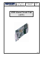
4200 ACU USER MANUAL Document Number: D00801R01 Issue: 6 4200 Alarm Circuit Unit (ACU) 99059 4200 ACU USER MANUAL Document Number: D00801R01 Issue: 6 TABLE OF CONTENTS 1. INTRODUCTION..............................................................................................................................................1 1.1 1.2 2. THEORY OF OPERATION.............................................................................................................................2 2.1 2.2 2.3 2.4 2.5 2.6 2.7 3. LINE SELECTION AND CONFIGURATION .....................................................................................................22 OUTSIDE PLANT (OSP) LINE CONFIGURATION ..........................................................................................22 ACU ~ MONITORING CONFIGURATION .....................................................................................................24 ACU MONITORING/OPERATION OVERVIEW......................................................................................27 5.1 6. ALARM CIRCUIT UNIT (ACU) CARD..........................................................................................................13 INSTALLATION AT THE CENTRAL OFFICE ..................................................................................................13 CONNECTING TO TERMINAL BLOCK (NORTH AMERICAN VERSION) ..........................................................15 CONNECTING TO TERMINAL BLOCK (UK AND EUROPEAN VERSION).........................................................16 INSTALLATION AT CABLE VAULT OR CABLE ENTRY LOCATION ................................................................17 INSTALLATION AT SPLICE ENCLOSURE ......................................................................................................19 INSTALLATION AT A TERMINATION ...........................................................................................................19 BATTERY FAIL SENSOR INSTALLATION: ....................................................................................................21 MULTIPLEXED REMOTE SENSOR INSTALLATION: ......................................................................................21 CONFIGURING THE ALARM CIRCUIT UNIT CARD ...........................................................................22 4.1 4.2 4.3 5. BASIC MONITORING SYSTEM CONCEPTS .......................................................................................................2 NORSCAN CABLE MANAGEMENT SYSTEMS .................................................................................................2 ACU MONITORING (USING STU TERMINATION SENSORS) .........................................................................2 ACU MONITORING (USING TSU TERMINATION SENSORS) .........................................................................5 SPLICE SENSOR UNIT (SSU) OPERATION.....................................................................................................8 BATTERY FAIL SENSOR (BFS) OPERATION .................................................................................................8 MULTIPLEXED REMOTE SENSOR (MRS) OPERATION ................................................................................10 INSTALLATION .............................................................................................................................................12 3.1 3.2 3.3 3.4 3.5 3.6 3.7 3.8 3.9 4. STANDARD FEATURES .................................................................................................................................1 SPECIFICATIONS ..........................................................................................................................................1 MONITORING OPERATION .........................................................................................................................27 APPENDIX A – SENSOR CONFIGURATION ...........................................................................................30 CONTACT INFORMATION .................................................................................................................................. 36 03/2011 Page: i 4200 ACU USER MANUAL Document Number: D00801R01 Issue: 6 List of Figures: Figure 1: Monitoring with Sequenced Termination Units (STU) ...................................................... 3 Figure 2: STU Theory of Operation Diagram .................................................................................... 3 Figure 3: Cable Alarm - STU Network Schematic ............................................................................. 4 Figure 4: STU Initialization/Status Test Sequence ............................................................................ 4 Figure 5: Line Alarm - STU Network Schematic ................................................................................ 5 Figure 6: Monitoring with Termination Sensor Units (TSU) ............................................................ 6 Figure 7: TSU Theory of Operation Diagram .................................................................................... 6 Figure 8: Cable Alarm - TSU Network Schematic ............................................................................. 7 Figure 9: Line Alarm - TSU Network Schematic ................................................................................ 7 Figure 10: Basic SSU Operation ......................................................................................................... 8 Figure 11: BFS Installation Diagram .................................................................................................... 9 Figure 12: MRS Install Diagram ......................................................................................................... 11 Figure 13: Typical Cable/Sensor Monitoring Installation ................................................................... 12 Figure 14: 4200 CMS Slot Designation ............................................................................................... 14 Figure 15: Transmitter Protection Assembly at Cable Vault (Building Entry) .............................. 18 Figure 16: Installation at Splice Enclosure ...................................................................................... 19 Figure 17: Termination Protection Assembly at Building Entry ..................................................... 20 Figure 18: Termination Installation in Splice Enclosure................................................................. 21 Figure 19: MRS Connections ............................................................................................................... 21 Figure 20:4200 CMS Main Menu ........................................................................................................ 22 Figure 21: Line Control Menu for OSP Line ....................................................................................... 23 Figure 22: Configure Line Menu ......................................................................................................... 23 Figure 23: Add Services Menu ............................................................................................................. 23 Figure 24: Configure Line Menu with armor monitoring .................................................................... 24 Figure 25: Armor configuration........................................................................................................... 24 Figure 26: Sensor and Set Line Type chart .......................................................................................... 25 Figure 27: Select a Baud Rate Menu ................................................................................................... 25 Figure 28: Line Control Menu for OSP Line ....................................................................................... 27 Figure 29: STU List .............................................................................................................................. 28 Figure 30: STU Test Results Table ...................................................................................................... 29 Figure 31: Line Control Menu ............................................................................................................. 31 Figure 32: Configure Line Menu ......................................................................................................... 31 Figure 33: Armor Configuration Menu ................................................................................................ 31 Figure 34: Sensor Configuration Menu ............................................................................................... 32 Figure 35: Select Sensor Type Menu.................................................................................................... 32 Figure 36: Sensor Code Menu ............................................................................................................. 32 Figure 37: Sensor Update Screen ........................................................................................................ 32 Figure 38: Sensor Configuration Screen ............................................................................................. 33 Figure 39: Sensor Configuration menu................................................................................................ 34 Figure 40: Select Sensor Type .............................................................................................................. 34 Figure 41: Armor configuration........................................................................................................... 34 Figure 42: Update Sensor - MRS ......................................................................................................... 35 Figure 43: Sensor Configuration - MRS .............................................................................................. 35 Figure 44: Senor Configuration – MRS Inputs .................................................................................... 35 03/2011 Page: ii 4200 ACU USER MANUAL 1. Document Number: D00801R01 Issue: 6 Introduction The 4200 Alarm Circuit Unit (ACU) plug-in card for the 4200 Cable Management System provides armor, copper pair or tracewire monitoring to an outside plant cable network along with sensor monitoring of splice enclosure, remote cabinet and building locations. The ACU can monitor up to 78 miles or 125 kilometers of cable armor/copper conductor and 799 sensor devices. The ACU employs Digital Signal Processing (DSP) circuitry that allows for adjustable filtering and for future enhancements to measurement and operation capabilities. Operating over a metallic conductor, such as a cable armor (fiber optic cable), copper pair or tracewire, the system will detect and warn the user of any damage to the protective cable jacket ensuring an adequate preparation time for repair. Providing proactive protection, the system cathodically protects the damage site, which inhibits corrosion of the metallic conductor, until a repair can be carried out. 1.1 1.2 Standard Features • Alarm thresholds fully adjustable via serial port, modem or telnet connection • Digitally coded Sensor Units monitor splice enclosures for moisture ingression, remote cabinets/buildings for environmental and equipment failure • Cathodically protects the metallic conductor to prevent corrosion Specifications Alarm Circuit Unit (ACU) Input Voltage Output Voltage Voltage Resolution Voltage Accuracy Output Current Current Resolution Current Accuracy Max. Monitoring Distance Maximum # of Branch Terminations Max. Induced AC Voltage Sensor Baud Rates 03/2011 -36 to-60 V dc -48.0 ± 0.5 V dc 10 mV dc ± 100 mV dc ± 25 mA dc ± 5.0 μA dc ± 10 μA dc 125/78 km/miles 20 on STU network, 5 on TSU network 16 V rms 3, 10, 32 baud Page: 1 of 36 4200 ACU USER MANUAL 2. Document Number: D00801R01 Issue: 6 Theory of Operation 2.1 Basic monitoring system concepts When cable infrastructures (which include interconnected splice enclosures, remote cabinet/building equipment) are exposed to the natural elements they can deteriorate, become damaged or stop functioning over time. Unfortunately, this is not the only cause of cable infrastructure damage. Accidental cable dig ups, vandalism and vehicle collisions with aerial installation structures also account for cable damage. One way to minimize the down time and reduce costly emergency repairs is to install a cable monitoring system. Cable monitoring is accomplished by using some or all of the following: 2.2 • Metallic cable shield(s) or armor • Copper pair conductor • Tracewire conductor • Splice enclosure sensors and moisture detection tape • Termination sensors • Battery Fail Sensors (remote cabinet/building) • Multiplexed Remote Sensors (remote cabinet/building) Norscan Cable Management Systems The 4200 ACU card is capable of providing cable, splice enclosure, end to end continuity and remote cabinet/building monitoring when installed in the 4200 CMS chassis. The ACU card will monitor the metallic conductor for faults to ground, end to end connectivity and sensor activation activity to give indication of the condition of the cable network infrastructure. Very specific sensor types (SSU, STU, TSU, BFS and MRS) are placed throughout the cable network to monitor for wet splices, termination point testing, remote cabinet/building battery, fans, heaters and power supplies devices just to name a few. The ACU card deciphers the codes that are transmitted from the activated sensors, which are then relayed to the 4200 CMS cable management and alarm reporting processes. 2.3 ACU Monitoring (Using STU Termination Sensors) The 4200 ACU card can be configured for monitoring a cable network using a Sequence Termination Sensor (STU). Using STUs allows for a cable network to have up to 20 monitored branches. The cable network system would be composed of lengths of cable joined at splice points that have Splice Sensor Units (SSU) installed and branches that are 03/2011 Page: 2 of 36 4200 ACU USER MANUAL Document Number: D00801R01 Issue: 6 terminated by STU sensors. This section will describe how Cable, Line and Sensor alarms are determined once the above-mentioned devices are installed (Figure 1). 4200 CMS Terminal STU 98 4200CMS 31 32 33 STU 99 01 02 03 20 21 22 STU 97 Splice/Security Sensors 41 42 43 Figure 1: Monitoring with Sequenced Termination Units (STU) The ACU card in the 4200 CMS is connected to the conductive metallic conductor and applies -48 V dc to the cable network system. The cable metallic conductors are connected together at the splice enclosures. Uniquely addressed Splice Sensor Units (SSUs) are connected in parallel between the metallic conductor (across Tip and Ring in copper pair applications) and ground at each splice enclosures to detect water ingression. The SSUs are electrically invisible until triggered by moisture that enters the enclosure. A STU sensor is a switch that simulates an open circuit resulting in a nominal line current of 0.00 mA in a system with no faults to ground and terminates the cable metallic conductor (Figure 2). 4200 CMS Terminal Open Termination STU 4200CMS - 48 V dc applied to Cable Armor SSU SSU SSU Nominal Loop Current 0.00 mA Figure 2: STU Theory of Operation Diagram When the polyethylene sheath becomes damaged (exposing the metallic conductor) the line current will start to increase depending on the size of the fault. This is referred to as 03/2011 Page: 3 of 36 4200 ACU USER MANUAL Document Number: D00801R01 Issue: 6 fault loop current. If the fault loop current exceeds a preset threshold, a Cable Alarm condition will appear on the 4200 CMS (Figure 3). R fault = 48V I faultcurrent Fault Location Detection Line M _ Fault Current 48 V dc Fault Resistance + C.O. GND Termination (STU) C.O. GND Figure 3: Cable Alarm - STU Network Schematic When installing a new metallic conductor cable network system or connecting additional branches to existing cable networks using STU sensors, a linear resistance measurement has to be recorded. This measurement is for comparison purposes to determine conductor continuity from the office equipment to each termination. A line initialization test must be performed on each ACU card to determine the nominal line resistance value for each STU sensor that is connected to the ACU card via the cable metallic conductor. This test applies a reverse polarity current to the cable network system, which causes each STU sensor to turn on sequentially (highest to lowest coded STU). Once activated, the highest number coded STU will first transmit its preprogrammed sensor code, which is decoded by the ACU card and then initiate the High Current Line Resistance test. It takes approximately three minutes for each STU sensor to complete the Initialization Test cycle. Once completed the nominal line resistance value is then recorded for each branch in the cable network system on the associated ACU card (Figure 4). Line Polarity Reversed Test Cycle Programmed Delay Period STU Code High Current Line Resistance Test Standby Figure 4: STU Initialization/Status Test Sequence 03/2011 Page: 4 of 36 4200 ACU USER MANUAL Document Number: D00801R01 Issue: 6 To check for sensor code decoding and end-to-end line continuity testing, the ACU card can be programmed to run a STU Status resistance test (daily or weekly) on a periodic basis. The test sequence is identical to what is shown on Figure 4. The test verifies that each STU sensor code can be received, thus verifying end-to-end continuity and making it safe to assume that the SSU codes can be decoded. The test also compares the recorded nominal resistance value of the Initialization Test to the measured resistance during a STU Status test. Changes in linear line resistance (metallic conductor continuity from the office equipment to each termination) are typically caused by a loose or corroded series bonds at splice points or by a break in the metallic conductor (detection line) as shown in Figure 5. If the measured line resistance value in the STU Status test exceeds the preset line resistance threshold above the nominal record resistance value, then a Line Alarm condition will appear on the 4200 CMS. Note: Normal monitoring operation is resumed after the STU Status test is completed. Open Fault Location Detection Line M _ Reversed Loop Current = 0 mA 48 Vdc + Closed for Test C.O. GND Termination (STU) C.O. GND Figure 5: Line Alarm - STU Network Schematic 2.4 ACU Monitoring (Using TSU Termination Sensors) The 4200 CMS uses an ACU card that can be configured for monitoring a cable network using a Termination Sensor Unit (TSU) and Branch Termination Sensors (BTS). The cable network system would be composed of lengths of cable joined by splices using Splice Sensor Units (SSU) with the main cable line terminated by one TSU sensor. In addition, branch termination is accomplished by the use of up to four Branch Termination Sensors (BTS) in conjunction with a TSU sensor. This section will describe how Cable, Line and Sensor alarms are determined (Figure 6). 03/2011 Page: 5 of 36 4200 ACU USER MANUAL Document Number: D00801R01 4200 CMS Terminal Issue: 6 BTS 98 4200CMS 31 32 33 TSU 99 01 02 03 20 21 22 BTS 97 Splice/Security Sensors 41 42 43 Figure 6: Monitoring with Termination Sensor Units (TSU) The ACU card in the 4200 CMS is connected to the conductive metallic conductor and applies –48 V dc to the cable armor network system. The cables and metallic conductors are connected together at the splice enclosures. Uniquely addressed Splice Sensor Units (SSUs) are also connected in parallel between the metallic conductor (across Tip and Ring in a copper pair cable network) and ground at the splice enclosure to monitor for ingression of water. The SSUs are electrically invisible until triggered moisture that enters the enclosure. The metallic cable conductor is terminated by a TSU sensor and up to four additional BTS sensors. The TSU sensor has a built in resistive load of 100kΩ that establishes a controlled current loop for the cable network system. BTS sensors have the same resistive load and must be taken into account when calculating controlled loop current. By applying the following Ohm’s law formula we can arrive at the Inom current which would be 0.48 mA for a TSU network with one termination (Figure 7). I nom = E 48V = = 0.48mA R 100kΩ 4200 CMS Terminal Termination TSU 100K 4200CMS - 48 V dc applied to Cable Armor SSU SSU SSU Termination Loop Current Figure 7: TSU Theory of Operation Diagram 03/2011 Page: 6 of 36 4200 ACU USER MANUAL Document Number: D00801R01 Issue: 6 The ACU card in the 4200 CMS applies a -48 V dc to the TSU cable metallic conductor network. In an ideal situation with no faults to ground the loop current (Inom) would be 0.48 mA. When the polyethylene sheath becomes damaged and exposes the metallic conductor, the loop current will start to increase. This is due to the parallel resistive fault and the TSU resistive path along the cable network system. If the cable network system’s loop current exceeds a preset limit, a Cable Alarm condition will appear on the 4200 CMS (Figure 8). Fault Location Detection Line M Fault Current _ 48 Vdc + Termination Loop Current Fault Resistance C.O. GND Termination 100 K - TSU C.O. GND Figure 8: Cable Alarm - TSU Network Schematic A drop in the loop current would result from an increase in the linear line resistance (metallic conductor continuity from the office equipment to each termination). This is typically caused by a loose or corroded series bonds at splice points or by a break in the metallic conductor (detection line) as shown in Figure 9. The line is considered “open” if the termination loop current drops below a preset threshold. If the cable network’s loop current drops below this preset limit, a Line Alarm condition will appear on the 4200 CMS. M Detection Line Open Fault Location _ 48 Vdc Loop Current = 0 mA + C.O. GND Termination 100 k - TSU C.O. GND Figure 9: Line Alarm - TSU Network Schematic 03/2011 Page: 7 of 36 4200 ACU USER MANUAL 2.5 Document Number: D00801R01 Issue: 6 Splice Sensor Unit (SSU) Operation In a splice enclosure the SSU sensor is connected in parallel, across the metallic conductor and local ground (across Tip and Ring in a copper pair network). The sensors are normally in the OFF state and draw no current from the line making the sensor appear electrically invisible and will not interfere with cable location tone equipment. If enough moisture enters the splice enclosure, causing the contract wires within the Moisture Detection Tape (MDT) to create an electrical short at the input leads of the SSU sensor, the sensor will turn ON. With current now flowing through the sensor, the SSU transmits a digitally coded address to the 4200 CMS causing a Cable/SSU alarm. A triggered sensor causes an increase of 1.5 - 2.5 mA in the detection line current. A Cable alarm may be registered simultaneously if the cable alarm fault level threshold is set within this current range (Figure 10). DETECTION LINE ELECTRONIC SWITCH MDT CODE GEN. SSU SSU DATA BURST GND Figure 10: Basic SSU Operation The communication for each Line has to be set correctly on the ACU card to match the type of sensors that are installed throughout the cable network. Currently there are four different sensor communication settings which are Standard, SISU, TSU or IRIS. Standard is used for legacy SSU, BFS and STU termination monitoring, SISU is used for MRS monitoring along with SSU, BFS and STU sensors that have product model number accompanied with a ‘-S’ designation. Both TSU and IRIS sensor communication is very specific to those types of sensor usage and is set accordingly. When installing sensors in a already populated outside plant cable network, make sure that the new sensors match the pre-existing sensor line communication scheme. 2.6 Battery Fail Sensor (BFS) Operation The Battery Fail Sensor (BFS) is designed to monitor a battery backup system at a Central Office or remote equipment locations using the 4200 ACU card. The BFS is connected to the monitored cable plant as is any other sensing element (Splice Sensor Unit (SSU), Sequenced Termination Unit (STU), etc). 03/2011 Page: 8 of 36 4200 ACU USER MANUAL Document Number: D00801R01 Issue: 6 Battery cells under constant charging will deteriorate over time. As the cells begin to deteriorate they draw more current from the charging source and will begin to heat up. When the cell overcharges the battery will begin to vent oxygen and hydrogen gases. These gases can become extremely explosive if they are allowed to accumulate in an enclosed area. This series of events can be avoided if early detection of the battery halfstring voltage variation or over-charging occurs. The BFS is designed to alarm when there is a change in battery cell voltage. The alarm is received by the CMS, and then forwarded to a NOC or maintenance center for immediate attention. Figure 11: BFS Installation Diagram The sensor portion of the BFS is powered from the line monitoring voltage provided from the 4200 ACU card. This ensures monitoring and alarm functionality in the event of a complete loss of battery power at the remote site. The sensing circuit is powered from the monitored battery string. The indicator LED on the BFS turns green when the midpoint voltage of the monitored battery string is within specification. It will turn red when the battery mid-point voltage goes outside the user selected threshold. The BFS can monitor up to four -48Vdc battery strings using a midpoint (-24Vdc) and a full string (-48Vdc) measurement. It uses the midpoint to effectively treat the battery string as two separate -24Vdc half-strings. Should one -24Vdc half-string vary from the other by more than the user selected threshold (0.5-1.75V) or the total battery string fails, the BFS will trigger an alarm. After a 60 second delay, the indicator LED will turn red and the BFS will transmit its user programmed code to the central office unit (4200 CMS) for processing and reporting to a NOC or maintenance center. 03/2011 Page: 9 of 36 4200 ACU USER MANUAL Document Number: D00801R01 Issue: 6 NOTE: The power light may turn off if either half-string voltage drops below -19Vdc. The BFS, however, will recognize this as a battery failure and still transmit its code to the CMS for processing. The BFS will continue to transmit its code until the line is reset or the string differential returns to within the failure threshold for more than 60 seconds (automatic). The alarm indication on the 4200 ACU card will remain until the line is reset (requires user acknowledgement and intervention). 2.7 Multiplexed Remote Sensor (MRS) Operation The Multiplexed Remote Sensor (MRS) is designed to provide security and equipment monitoring to remote cabinet/building locations. A typical installation would be in a DSLAM or E-Cabinet, other locations could be Environmental Vaults or Fiber Optic Repeater Huts. The MRS is used in conjunction with 4200 ACU card and operates as all the other Norscan sensors do when activated. Each MRS that is installed in a cable network is configured with a Base Code (i.e. 1, 17, 33 etc) which represents 16 input connections along with an associated STU code (used for end to end testing). The MRS can monitors up to 16 normally open contact closure inputs. These inputs may monitor such conditions as: • Security – Access doors • Commercial AC supply • Rectifiers – Major & Minor • DSL – Major & Minor • Environmental Temperature – Major & Minor • Back-up Battery – Operation & Condition • Moisture – Humidity and/or pit water level Once a specific MRS input is activated, the input code is received by the 4200 ACU card which activates the alarm process on the 4200 CMS unit. Information regarding the location of the MRS and which input was activated is relayed in the Alarm Report via email, SMS, SNMP or modem communication. 03/2011 Page: 10 of 36 4200 ACU USER MANUAL Document Number: D00801R01 Issue: 6 Figure 12: MRS Install Diagram The status of each MRS connected to the 4200 ACU card and its designated Line (1, 2, 3 or 4) can be tested to verify the operation of each unit. When a status test (end to end code check) is executed, each MRS will be polled and its STU code is expected to be received. If a MRS does not respond with its STU code, a Line Alarm will be forwarded to the alarm monitoring center. 03/2011 Page: 11 of 36 4200 ACU USER MANUAL 3. Document Number: D00801R01 Issue: 6 Installation The following instructions will explain the installation of a 4200 Cable Management System that is used in conjunction with a 4200 ACU card for metallic cable conductor and sensor monitoring. A typical monitored cable network is illustrated in Figure 13 with the 4200 CMS unit located in the originating central office. In operation, the metallic conductor (armored cable, copper pair or tracewire) becomes a sensing element which can give indication of damage to the protective outer jacket (creating a resistive fault to ground), once detected, will cause cable alarms. To prevent corrosion at any damaged site, the system inherently applies a protective cathodic current to the metallic conductor. Addressable sensors are strategically placed throughout the cable network to monitor for specific occurrences. Splice Sensor Unit (SSU) and Moisture Detection Tape (MTD) are placed in every splice enclosure to monitor for wet splices. The Sequence Termination Units are place at the end of each line/branch and monitor the metallic conductor to ensure that end to end connectivity is maintained along with end of line sensor decode testing. Remote cabinet/building monitoring is achieved by placing Battery Fail and Multiplexed Remote Sensors at those locations to indicate the environmental or equipment operation status. Figure 13: Typical Cable/Sensor Monitoring Installation 03/2011 Page: 12 of 36 4200 ACU USER MANUAL 3.1 Document Number: D00801R01 Issue: 6 Alarm Circuit Unit (ACU) card The Alarm Circuit Unit card provides constant monitoring of the metallic conductor (detection line) for sensor activation signals, end to end continuity, and faults to ground damage. Each ACU card can monitor up to 78 miles or 125 kilometers of continuous metallic cable conductor or any combination of cables whose combined length is 78 miles or 125 kilometers. The ACU card can be configured to operate in one of four different line monitoring modes which are related to the type of communication schemes that the sensors are using to transmit sensor codes. The four types of communication schemes that are available are Standard, SISU, TSU or IRIS. The sensor communication requirement is identified by the model number printed on the sensor label. Model numbers that are not identified with a ‘-S’ are Standard communication, with a ‘-S’ are SISU, TSU model number uses TSU communication and IRIS model numbers use IRIS. MRS sensors can only use SISU communication because of the possibility of multiple alarm activations at the same time. Each Alarm Circuit Unit card can monitor up to 799 sensor cable monitoring devices. Security products such as the BFS, IRIS or MRS sensors have limits to the number of these types of sensors that can be installed on an outside plant line, contact Norscan for more details. In an ACU/STU network this would include up to 20 STUs and the remaining would be Splice Sensor Units (SSU). In an ACU/TSU network this would include 1 TSU, up to 4 Branch Termination Sensors (BTS) or Branch Circuit Terminations (BCT), and the remaining number can be Splice Sensor Units (SSU). 3.2 Installation at the Central Office The Alarm Circuit Unit card (ACU) card can be installed in slots 3, 4, 5 or 6 of the 4200 CMS chassis. Note: A Maximum of four ACU cards can be installed in one 4200 CMS chassis. Ensure that the 4200 CMS unit is powered off before installing or removing any of the cards from the chassis. 03/2011 Page: 13 of 36 4200 ACU USER MANUAL LIC AUIC Slot Slot Document Number: D00801R01 Issue: 6 Slots 3 to 6 Optional Cards Figure 14: 4200 CMS Slot Designation Figure 14 above illustrates the exposed plug-in slot designation when the back panel is removed. Slots 1 and 2 are reserved for the LIC and AUIC cards that are keyed to only allow these two cards to fit into the first two slots respectively. Slots 3 to 6 can accommodate up to 4 optional plug-in cards that are available for this system. As mentioned earlier up to 4 ACU cards can be installed in the 4200 CMS chassis to accommodate four outside plant lines for cable armor monitoring. 03/2011 Page: 14 of 36 4200 ACU USER MANUAL 3.3 Document Number: D00801R01 Issue: 6 Connecting to Terminal Block (North American version) Connect all wires carefully to the terminal block according to your cable system network. A description of each connection is explained in Table A. POSITION FUNCTION DESCRIPTION TB1-1 -48 Vdc Central office battery voltage connection to -48 Vdc supply. Use a minimum 16 American Wire Gauge (AWG) wire. Must be fused at 5 amps. TB1-2 GND Earth or Station ground connection. Use a minimum 16 American Wire Gauge (AWG) wire. Note: Not to be confused with CPS Anode GND. TB1-3 LINE 1 Input connection line for ACU metallic conductor monitoring or MTM tone access line. Use a minimum 24 AWG wire. Warning: Must be connected to a Transmitter Protection Assembly unit at the cable vault area. Shock Hazard Warning (Page 22). TB1-4 LINE 2 Input connection line for ACU metallic conductor monitoring or MTM tone access line. Use a minimum 24 AWG wire. Warning: Must be connected to a Transmitter Protection Assembly unit at the cable vault area. Shock Hazard Warning (Page 22). TB1-5 LINE 3 Input connection line for ACU, CPS metallic conductor monitoring or MTM tone access line. Use a minimum 24 AWG wire. Warning: Must be connected to a Transmitter Protection Assembly unit at the cable vault area. Shock Hazard Warning (Page 22). or CPS1 or CPS2 Input connection line for ACU, CPS metallic conductor monitoring or MTM tone access line. Use a minimum 24 AWG wire. Warning: Must be connected to a Transmitter Protection Assembly unit at the cable vault area. Shock Hazard Warning (Page 22). TB1-7 CPS ANODE GND Cathodic protection sacrificial Anode Ground connection. Use a minimum 10 AWG wire to connect Anode Ground to this terminal. Note: Not to be confused with GND. TB1-8 EQUIPMENT ALARM Output connection for an external supervisory alarm system. Use a minimum 24 AWG wire. (Relay switch is normally in OPEN state) TB1-9 ALARM COMMON Common connection for an external supervisory alarm system. Use a minimum 24 AWG wire. TB1-10 MONITORING ALARM Output connection for an external supervisory alarm system. Use a minimum 24 AWG wire. (Relay switch is normally in OPEN state) TB1-11 PHONE TIP Input connection phone tip line for using modem communication. Use a minimum 24 AWG wire. TB1-12 PHONE RING Input connection phone ring line for using modem communication. Use a minimum 24 AWG wire. TB1-6 LINE 4 Table A: TB1-Terminal Block Connections (North American version) 03/2011 Page: 15 of 36 4200 ACU USER MANUAL 3.4 Document Number: D00801R01 Issue: 6 Connecting to Terminal Block (UK and European version) Connect all wires carefully to the terminal block according to your cable system network. A description of each connection is explained in Table B. POSITION FUNCTION DESCRIPTION TB1-1 -48 Vdc Central office battery voltage connection to -48 Vdc supply. Use a minimum 16 American Wire Gauge (AWG) wire. Must be fused at 5 amps. TB1-2 GND Earth or Station ground connection. Use a minimum 16 American Wire Gauge (AWG) wire. Note: Not to be confused with CPS Anode GND. TB1-3 LINE 1 Input connection line for ACU metallic conductor monitoring or MTM tone access line. Use a minimum 16 AWG shielded twisted pair wire (typical length 10 meters). Warning: Must be connected to a LPU and IVF at the cable vault. LPU not required with MTM. TB1-4 LINE 2 Input connection line for ACU metallic conductor monitoring or MTM tone access line. Use a minimum 16 AWG shielded twisted pair wire (typical length 10 meters). Warning: Must be connected to a LPU and IVF at the cable vault. LPU not required with MTM. TB1-5 LINE 3 Input connection line for ACU/CPS metallic conductor monitoring or MTM tone access line. Use a minimum 16 AWG shielded twisted pair wire (typical length 10 meters). Warning: Must be connected to a LPU and IVF at the cable vault. LPU not required with MTM. or CPS1 or CPS2 Input connection line for ACU/CPS metallic conductor monitoring or MTM tone access line. Use a minimum 16 AWG shielded twisted pair wire (typical length 10 meters). Warning: Must be connected to a LPU and IVF at the cable vault. LPU not required with MTM. TB1-7 CPS ANODE GND Cathodic protection sacrificial Anode Ground connection. Use a minimum 10 AWG wire to connect Anode Ground to this terminal. Note: Not to be confused with GND. TB1-8 EQUIPMENT ALARM Output connection for an external supervisory alarm system. Use a minimum 24 AWG wire. (Relay switch is normally in OPEN state) TB1-9 ALARM COMMON Common connection for an external supervisory alarm system. Use a minimum 24 AWG wire. TB1-10 MONITORING ALARM Output connection for an external supervisory alarm system. Use a minimum 24 AWG wire. (Relay switch is normally in OPEN state) TB1-11 PHONE TIP Input connection phone tip line for using modem communication. Use a minimum 24 AWG shielded twisted pair wire (typical length 1.5 meters). TB1-12 PHONE RING Input connection phone ring line for using modem communication. Use a minimum 24 AWG shielded twisted pair wire (typical length 1.5 meters). TB1-6 LINE 4 Table B: TB1-Terminal Block Connections (UK & European version) 03/2011 Page: 16 of 36 4200 ACU USER MANUAL 3.5 Document Number: D00801R01 Issue: 6 Installation at Cable Vault or Cable Entry Location It is recommended that a Transmitter Protection Assembly (includes two Induced Voltage Filters (IVF) and two TI355 Gas Tubes) be installed at the Cable Vault or Building Entry Location. The use of these devices prevent the potential for stray voltage surges or induced AC voltages from causing serious harm to personnel, equipment and the cable itself. Note: This applies to all 4200 CMS systems that are using ACU, CPC cards and MTM modules. The Transmitter Protection Assembly is mounted to the wall surface in close proximity to the cable vault area. Connect the metallic conductor from the outside plant to the appropriate connection terminals (East/North, West/South) as they are labeled on the front cover of the assembly. Using a feeder cable (usually 22 gauge, 4 wire, twisted pair shielded cable), connect the 4200 CMS line 1, 2, 3 or 4 to the L1 or L2 terminal block (one line per terminal block, Line 1 to L1, Line 2 to L2) in the Transmitter Protection Assembly. When using twisted pair wire, make sure that one wire of the pair is to L1 or L2 and the other wire of the pair is to GND of the terminal block. Ground the entire Transmitter Protection Assembly by connecting the Ground/Earth terminal to Building Ground (Figure 15). Warning! Potential for electrical shock exists when handling cables while the Alarm Circuit Unit (ACU) card is activated or the Multi Tone Module (MTM) is transmitting tone frequencies. Make sure that the ACU card is set to OFF and that the MTM is not transmitting tone on the cable that is being handling at that particular time. Always take DC and AC measurements using a Norscan 1303 System Test Set or a Multi-meter to determine what AC or DC voltages are present before handling the cable. Note: Induced AC and transient voltages can also be present on the cable armor. Temporarily hard ground the cable armor before handling the cable in the central office, outside plant splice or remote termination location. Once the work is completed, remove the hard ground connection to the cable armor. Remove the cable armor connection first and then the local ground connection. 03/2011 Page: 17 of 36 4200 ACU USER MANUAL 2303 IVF (60 Hz) or 2313 IVF (50 Hz) Document Number: D00801R01 Issue: 6 2303 IVF (60 Hz) or 2313 IVF (50 Hz) L1 GND L2 To 4200 CMS GND To 4200 CMS EAST/NORTH ARMOR GROUND/ EARTH WEST/SOUTH ARMOR Figure 15: Transmitter Protection Assembly at Cable Vault (Building Entry) 03/2011 Page: 18 of 36 4200 ACU USER MANUAL 3.6 Document Number: D00801R01 Issue: 6 Installation at Splice Enclosure The following diagram illustrates the proper way of connecting the cable conductors for monitoring, along with the connection of both the SSU and MDT (Figure 16). SPLICE ENCLOSURE M T D BLUE RD/OR SSU WHITE Figure 16: Installation at Splice Enclosure 3.7 Installation at a Termination It is recommended that a Termination Protection Assembly (includes two Induced Voltage Filters (IVF), two Line Termination Units (LTU) and two STU, TSU or BTS terminations) be installed at the Cable Vault or Building Entry Location. The STU, TSU and BTS terminations are used to terminate the cable monitoring system. The LTUs are used to provide a return ground path for a tone generated signal for the MTM module which is used in cable locate exercises. The LTU not required for cable and splices monitoring. The STU, TSU and BTS devices have gas tubes embedded in their circuitry, so along with the IVF units, prevent the potential for stray voltage surges or induced AC voltages from causing serious harm to personnel, equipment, and the cable itself. The Termination Protection Assembly is mounted to the wall surface in close proximity to the cable vault area. Connect the cable conductor from the outside plant to the appropriate connection terminals (East/North, West/South) as they are labeled on the front cover of the assembly. Ground the entire Transmitter Protection Assembly by connecting the Ground/Earth terminal to Building Ground (Figure 17). Note: Remember to program the termination sensors out of circuit and reconnect accordingly once programming is complete. 03/2011 Page: 19 of 36 4200 ACU USER MANUAL Document Number: D00801R01 Issue: 6 Model 51300 - TERMINATION PROTECTION ASSEMBLY 2303 IVF (60 Hz) or 2313 IVF (50 Hz) EAST/NORTH ARMOR 2230 STU GROUND/ EARTH 2316 LTU FC or 0K BLUE WHITE WHITE 2230 STU 2316 LTU FC or 0K BLUE 2303 IVF (60 Hz) or 2313 IVF (50 Hz) WEST/SOUTH ARMOR Label P/N 50130 Figure 17: Termination Protection Assembly at Building Entry 03/2011 Page: 20 of 36 4200 ACU USER MANUAL Document Number: D00801R01 Issue: 6 The following diagram illustrates the proper way of connecting a Termination Sensor (STU, TSU, & BTS) in a splice enclosure (Figure 18). SPLICE ENCLOSURE D M T BLUE 22ga MDT LEADS STU / TSU / BTS WHITE Figure 18: Termination Installation in Splice Enclosure 3.8 Battery Fail Sensor Installation: Once the BFS sensor is securely mounted within the remote cabinet or building location, connect the BFS leads to the cable network and batteries as illustrated by the chart below. BFS Red Purple Grey Brown Yellow Black Blue White 3.9 CONNECTION Monitored Battery –48 Vdc Monitored Battery Mid-Point 4 Monitored Battery Mid-Point 3 Monitored Battery Mid-Point 2 Monitored Battery Mid-Point 1 Monitored Battery Ground CMS Monitored Line CMS Ground (-24 Vdc) (-24 Vdc) (-24 Vdc) (-24 Vdc) Multiplexed Remote Sensor Installation: Once the MRS sensor is securely mounted within the remote cabinet or building location, connect the MRS leads to the cable network as illustrated by the picture below. Terminals 1C to 16C are input connections, Line is cable network connection and GND is ground. Figure 19: MRS Connections 03/2011 Page: 21 of 36 4200 ACU USER MANUAL 4. Document Number: D00801R01 Issue: 6 Configuring the Alarm Circuit Unit card This section will explain the configuration of a 4200 ACU with an AUIC. Connect to the 4200 CMS via serial, modem or Telnet connection and login using the administrator or diagnostic access. For connection and login details see the 4200 Cable Management System (CMS) with AUIC user manual. 4.1 Line Selection and Configuration The Main Menu allows the user to configure up to four outside plant lines that correspond to the number of ACU cards that are installed in the 4200 CMS chassis. Each line must have an individual ACU card associated with it to perform cable monitoring. Lines 1, 2, 3, and 4 are designated for cable monitoring and are associated with the TB1 terminal block connection on the back of the 4200 CMS chassis. To configure a Line for cable monitoring, select the line you want to configure by positioning the arrow beside Line 1, 2, 3 or 4 (Figure 20) and press enter. -> Line Line Line Line 1. 2. 3. 4. <no <no <no <no Main Menu description> - no cards description> - no cards description> - no cards description> - no cards connected connected connected connected System Configuration Comms Configuration Date/Time Configuration Tone Frequency Configuration Alarm Target Configuration Diagnostics Quit Figure 20:4200 CMS Main Menu 4.2 Outside Plant (OSP) Line Configuration The Main Menu (Figure 20) shows each outside plant (OSP) line connected to the TB1 connector on the rear of the 4200 CMS and each fiber connected to an Optical Alarm Unit (OAU). Lines one through four are the OSP lines and lines five through twelve are used for optical monitoring. A user programmed line description identifies each line. The message “no cards connected” will appear on an OSP line if there are no services associated with that line. To configure an OSP line, highlight the desired line number (1 – 4) on the 4200 CMS Main Menu and press enter. The Line Control Menu will be displayed (Figure 21). 03/2011 Page: 22 of 36 4200 ACU USER MANUAL Document Number: D00801R01 Issue: 6 Line Control Menu Line 1: <no description> Tone :OFF Activate Tone (577Hz) Activate tone safety lock -> Configure Line.. Back Figure 21: Line Control Menu for OSP Line Select the Configure line option to open the Configure Line Menu (Figure 22). Configure Line Menu Select tone frequency (577Hz) Change tone auto-shutoff period (10 hours) -> Add a service… Remove a service… Change line description Back Figure 22: Configure Line Menu The Configure Line Menu allows configuration of services that are available on the current line. The tone locating service is always available on the line if the MTM module is install into the 4200 CMS chassis; any additional services must be added to the line in order to be used. Add a service: Select this option to add a service to the current line. The Add Service Menu will appear (Figure 23). This menu will list all the services that are available for the selected line. Select Armor monitoring (metallic conductor ~ armored cable, copper pair or tracewire) for the line and press enter (Administrator or Diagnostic login only). Add Services Menu -> Armor monitoring Back Figure 23: Add Services Menu Remove a service: Select this option to remove a service from the current line. The Remove Service Menu will appear listing the services currently on the line. Select a service to remove and press enter (Administrator or Diagnostic login only). Change line description: This option allows the user to change the line description for the current line (Administrator or Diagnostic login only). The line description is used to identify the line in any alarm reports and on-screen menus. 03/2011 Page: 23 of 36 4200 ACU USER MANUAL 4.3 Document Number: D00801R01 Issue: 6 ACU ~ Monitoring Configuration The armor (metallic conductor ~ armored cable, copper pair or tracewire) monitoring service must be added to activate armor monitoring. To set up the monitoring select an OSP line and add the armor monitoring service as described in section 4.2 Outside Plant (OSP) Line Configuration. The Configure Line Menu (Figure 24) will now have an option for configuring armor monitoring (Administrator or Diagnostic login only). Configure Line Menu -> Configure armor monitoring… Configure tone locating… Add a service… Remove a service… Change line description… Back Figure 24: Configure Line Menu with armor monitoring Select the Configure Armor Monitoring and press enter. The armor configuration menu will appear (Figure 25). Armor Configuration -> Set Line type <Standard> Toggle alarm reporting <ON> Set alarm delay <5 min> Sensor baud <03 baud/normal> Set line alarm threshold <400 R> Set cable alarm threshold <1 mA> Clear STU data Initialize STUs Set lowest STU code Setup automatic STU tests Configure sensors… Back <Unset> <Off> Figure 25: Armor configuration To configure armor monitoring, review the following armor configuration settings and press enter to change an option. • 03/2011 Set line type: It is important to match the communication of the sensors installed in the outside plant to the proper communication setting on the ACU card to insure proper decoding of the sensors when activated Figure 26. When this option is selected, a warning will appear stating that changing the Line type (sensor communication scheme) will reset all settings to default (press enter on <OK> or tab to <Cancel> and press enter). If <OK> was selected from the warning screen, the Select line type menu will appear. Select the type that matches the type of Page: 24 of 36 4200 ACU USER MANUAL Document Number: D00801R01 Issue: 6 sensors that are installed in the outside plant; Standard (SSU/STU sensors labeled 1107B or 1107C SSU, 2230B or 2230C STU), SISU (SSU/STU sensors labeled 1107B-S or 1107C-S SSU, 2230B-S or 2230C-S STU, 1160 MRS), TSU (TSU sensors labeled 2207B or 2207C) and IRIS (when using the infrared motion sensor). Default is Standard. Sensor Model Type Set Line Type to: 1107B or 1107C (SSU) 2230B or 2230C (STU) 1107B-S, 1107C-S (SSU) 2230B-S, 2230C-S (STU), 1160 MRS 2207B or 2207C (TSU) 1151 IRIS Standard Standard SISU SISU SISU TSU IRIS Figure 26: Sensor and Set Line Type chart If this ACU card will be used for security products, chose either the MRS or IRIS according to the product installed. If the IRIS security product is installed you will be prompted to enter the total number of IRIS sensors that are installed on the line. Note: There are limitations to the number security sensors that can be installed on each ACU card, contact Norscan for more details. • Toggle alarm reporting: Activate or deactivate the armor alarm reports. Default is ON. • Set alarm delay: Set the delay between an alarm occurring and the delivery of the alarm report. Default is 5 min. • Set baud rate: This option will display the Select a Baud Rate Menu (Figure 27). Select the baud rate of the monitored sensors and the characteristics of the OSP line being monitored and press enter. Default is 03 baud/normal. Select a Baud Rate -> 03 baud/normal 10 baud/normal 32 baud/normal 03-10 baud/normal 03 baud/high cap Figure 27: Select a Baud Rate Menu 03/2011 Page: 25 of 36 4200 ACU USER MANUAL Document Number: D00801R01 Issue: 6 • Set line alarm threshold: Set the maximum difference between the nominal line resistance and the last tested value before a line alarm will occur. Default is 400Ω. • Set cable alarm threshold: Set the maximum difference between the nominal line current and the present current before a cable alarm will occur. Default is 1.0mA. Next, complete the following steps to configure and initialize the STUs. Note: The Initialization process has to be performed on new installations or if any new branches are added to an existing cable network system. Initializing an STU cable network should only be done when the monitored line has no faults or relatively low fault current (below 1.0mA) on the ACU card. • Clear STU data: Select this option to clear all the termination data for the current line. • Set lowest STU code: Enter the lowest numbered STU code that is installed on the current line and press enter. Testing will begin with STU code x99 and decrease by one for each subsequent test until the lowest STU code has been tested. For example, on a line with three terminations the STU codes will be 99, 98, and 97 so the lowest STU code will be 97. • Initialize STUs: This option will execute a STU test and record the nominal resistance of the current line. The line will not be initialized if the lowest STU code has not been entered. The recorded nominal resistance will be compared to the resistance measured during a termination test to check the end-to-end continuity of the OSP line. • Setup automatic STU tests: Select this option to program the frequency of the automatic termination tests. If daily or weekly is selected the user will be prompted for an hour and a day to run the test. Default is off. The termination test will check the end-to-end continuity by measuring the line resistance of the OSP line and perform a sensor decode operation. If either of the tests fails a line alarm will occur. • Configure sensor: This option allows the user to enter a description for a specific sensor code (for more detailed instructions see Appendix – A of this manual). When this option is selected, a menu will appear showing all the previously entered sensor descriptions for this Line and an option for adding a sensor description. To add a sensor description, select Add Sensor and press enter. Type the sensor code and description and press enter on OK to accept the changes. 03/2011 Page: 26 of 36 4200 ACU USER MANUAL 5. Document Number: D00801R01 Issue: 6 ACU Monitoring/Operation Overview This section describes the operational functions of the ACU card and how cable armor (and/or copper pair or tracewire) monitoring is achieved when installed in a 4200 CMS chassis with an AUIC (Advanced User Interface Card). 5.1 Monitoring Operation To view or control the monitoring functions, ensure the monitoring service has been added to the desired line (see section 4.2 Outside Plant (OSP) Line Configuration) then select the OSP line from the main menu and press enter. The Line control menu will appear (Figure 28). Line 1: Sensor Armor Tone Line Control Menu <no description> :Standard no alarms :ON –0.00mA >150kR no alarms :OFF ->Deactivate armor monitoring Reset alarms Perform termination test View test results Activate tone (577Hz) Activate tone safety lock Configure line… Back Figure 28: Line Control Menu for OSP Line The first four lines of the Line Control Menu show the current status of the OSP line. 03/2011 • Line x: Indicates which OSP line is being displayed and the corresponding user line description. Where x is the current line number (1,2,3 or 4 on the TB1 connector on the rear panel of the 4200 CMS). • Sensor: This indicates the sensor communication scheme (Standard, SISU, TSU or IRIS) of the OSP line and any line or sensor alarms that are currently triggered. If a sensor is in an alarm state the sensor code is shown. If the termination test has failed a line alarm is indicated and the termination code if any is shown. All reporting of the sensor or line alarms are processed through the AUIC card, refer to the 4200 CMS with AUIC manual for alarm reporting setup instructions. • Armor: Shows the fault current and resistance between armor/copper conductor and ground on the selected OSP line. When the resistance between the armor/copper conductor and ground is greater than 150kΩ the display will show >150kR. If the fault current exceeds the preset cable alarm threshold a cable Page: 27 of 36 4200 ACU USER MANUAL Document Number: D00801R01 Issue: 6 alarm will occur and is indicated by cable alarm. All reporting of the cable alarms are processed through the AUIC card, refer to the 4200 CMS with AUIC manual for alarm reporting setup instructions. • Tone: Shows the status of the locating tone on the current line. The Line control menu items are used to control the armor monitoring functions. Deactivate armor monitoring: This option is used to toggle the –48 Vdc monitoring voltage that is applied to the armor/copper conductor. Use this option to disable the monitoring without losing saved termination data. Reset alarms: This option will reset all alarms on the current OSP line. Any faults or sensor codes still active on the OSP line will re-alarm after the alarm delay has passed. Perform termination test: When this option is selected, a termination test will be executed on the current OSP line. The termination test will check the end-to-end continuity and termination sensor decoding of the OSP line. With a STU termination, this test will also measure the line resistance and compare it to the initial value recorded when the STU initialization was completed. View test results: Use this option to view the results of the termination test. Test results will only be shown if the line has been properly initialized. For STU terminations, select the branch to be displayed and press enter (Figure 29), a table will appear that shows the initialized line resistance and the line resistance of the last termination test (Figure 30). Note: The MRS unit has a built in STU sensor which is used for termination testing (end to end code check). The STU code that is assigned to the MRS is dependent on the Base Code programmed into the MRS sensor (see Table 4). STU List -> 97: 98: 99: Back Figure 29: STU List 03/2011 Page: 28 of 36 4200 ACU USER MANUAL Document Number: D00801R01 Issue: 6 View Sensor Data Line 1: <no description> STU 99: Termination description | Current | Voltage | Resistance | Code | |-----------+-----------+------------+------ | Nominal | 7.41 mA | 35.3 V | 1.44 kR | 99 | Last Test | 7.41 mA | 35.3 V | 1.44 kR | 99 | +-----------+-----------+------------+------+ Status Resistance Threshold: Test result: 400 Normal <Back> Figure 30: STU Test Results Table The test result field will display one of the following test results: Normal: Termination test passed line is OK. Alarm: The termination test failed. If the termination test failed, one or both of the following alarms will be displayed: Missed Code: The 4200 did not receive the STU code. High Resistance: The line resistance has increased by more than the resistance threshold. 03/2011 Page: 29 of 36 4200 ACU USER MANUAL 6. Document Number: D00801R01 Issue: 6 Appendix A – Sensor Configuration The 4200 AUIC card contains a database that allows for the configuration of a variety of sensors that are installed within the outside plant cable network. Specific details regarding sensor type (SSU, STU, BFS, IRIS or MRS), code, description and location can be stored within the database. Note: The AUIC ‘Plus” version of firmware will allow for more descriptive Alarm Reports. The AUIC standard version will only report very basic information regarding the alarm occurrence (i.e. gives sensor code number with no Description or Location information). TYPE FUNCTION DESCRIPTION SSU Water Ingression Mainly installed in below grade splice enclosures and monitors for water ingression into the splice enclosure within an armored cable or copper conductor network. End to End line testing and water ingression Mainly installed in a building termination point for armored cable or copper conductors and is used to test end to end continuity and sensor communication. Can be installed in a below grade line terminating splice enclosure when monitoring for water ingression is required. Remote cabinet monitoring and end to end testing Installed in remote cabinets or building locations. Has 16 normally open alarm contact points for various alarm switch devices. Is equipped with termination point sensor code testing as used in the STU termination test. Remote cabinet battery fail monitoring Installed in remote cabinets or building locations for battery fail monitoring. Termination testing and water ingression Mainly installed in a building termination point for armored cable or copper conductors and is used to test for end to end continuity and sensor communication. Can be installed in a below grade line terminating splice enclosure when monitoring for water ingression is required. Intruder detection Installed in remote buildings or man-hole infrastructures to detect physical entry of normally secured areas. Splice Sensor Unit STU Sequence Termination Unit MRS Multiplexed Remote Sensor BFS Battery Fail Sensor TSU Termination Sensor Unit IRIS Infrared Intrusion Sensor Table 3: Sensor Description and Function 03/2011 Page: 30 of 36 4200 ACU USER MANUAL Document Number: D00801R01 Issue: 6 To initiate the sensor configuration process, arrow down to Configure line from the Line Control Menu. Line 1: Sensor Armor Tone Line Control Menu <City Center – North Cable> :Standard no alarms :ON –0.00mA >150kR no alarms :OFF Deactivate armor monitoring Reset alarms Perform termination test View test results Activate tone (577Hz) Activate tone safety lock -> Configure line… Back Figure 31: Line Control Menu Select Configure armor monitoring from the Configure Line Menu. Configure Line Menu -> Configure armor monitoring… Configure tone locating… Add a service… Remove a service… Change line description… Back Figure 32: Configure Line Menu Select Configure sensors from the Armor Configuration menu Figure 33. Armor Configuration Set Line type <Standard> Toggle alarm reporting <ON> Set alarm delay <5 min> Sensor baud <03 baud/normal> Set line alarm threshold <400 R> Set cable alarm threshold <1 mA> Clear STU data Initialize STUs Set lowest STU code Setup automatic STU tests -> Configure sensors… Back <Unset> <Off> Figure 33: Armor Configuration Menu 03/2011 Page: 31 of 36 4200 ACU USER MANUAL Document Number: D00801R01 Issue: 6 The next screen prompt is to add a sensor to the database, press enter to proceed. Sensor Configuration ->Add sensor Back Figure 34: Sensor Configuration Menu The Select Sensor Type menu will appear. Arrow down to the sensor type you would like to configure and press enter when done. Select Sensor Type -> Unconfigured SSU STU MRS BFS TSU IRIS Figure 35: Select Sensor Type Menu For SSU, STU, BFS, TSU and IRIS sensors, the configuration process is the same. You will be prompted to enter a sensor code number. Enter the sensor code that correlates with the number of the sensor that was install in the outside plant. Press enter when done and once more on <OK> or tab to <Cancel> and press enter. Note: Limited to a 3 digit code. Sensor Code: 123 <OK> <Cancel> Figure 36: Sensor Code Menu The next screen allows for the programming of specific identification of the sensor code that was just entered. If there are no changes to be made to the Sensor Type or Sensor Code press the <Tab> key to move to the Description and Location entries. Enter in the appropriate information in for the Description and Location of the sensor, press enter on <OK> when done or tab to <Cancel> the sensor update process. Repeat the Add Sensor as required until all sensors are programmed into the database. Update Sensor Sensor Type:[ SSU ] Sensor Code: 80 Description: North Line__________________ Location: Main and 1st Ave.____________ <OK> <Delete Sensor> <Cancel> Figure 37: Sensor Update Screen 03/2011 Page: 32 of 36 4200 ACU USER MANUAL Document Number: D00801R01 Issue: 6 Once all the sensors have been configured into the database the Sensor Configuration screen will list the sensors that are currently in the database. If required, modifications can be done to any of the sensors by simply highlighting the sensor using the arrow key and pressing enter. Sensor Configuration SSU 80, North Line, Main and 1st Ave. ->SSU 120, North Line, Main and 22nd Ave. STU 99, North Line Termination, Build #30 Add sensor Back Figure 38: Sensor Configuration Screen MRS Configuration: To configure the database when using MRS units within the outside cable plant network, certain rules are followed in order for the database to work properly. As indicated by the table below, each MRS unit has a Base Code which represents a block of 16 sensor code inputs along with a termination Status Code. Base code ‘001’ represents 1 to 16 sensor code inputs with a termination Status Code of 99, base code ‘017’ represents 17 to 32 sensor code inputs with a termination Status Code 98 and so on. Defender Number 1 2 3 4 5 6 7 8 9 10 11 12 13 14 15 16 17 18 19 20 21 22 23 24 25 26 27 28 29 30 Base Code 001 017 033 049 065 081 097 113 129 145 161 177 193 209 225 241 257 273 289 305 321 337 353 369 385 401 417 433 449 465 Sensor Codes min max 001 016 017 032 033 048 049 064 065 080 081 096 097 112 113 128 129 144 145 160 161 176 177 192 193 208 209 224 225 240 241 256 257 272 273 288 289 304 305 320 321 336 337 352 353 368 369 384 385 400 401 416 417 432 433 448 449 464 465 480 Status Code 99 98 97 96 95 94 93 92 91 90 89 88 87 86 85 84 83 82 81 80 79 78 77 76 75 74 73 72 71 70 Table 4: MRS Base Code and Cross Reference 03/2011 Page: 33 of 36 4200 ACU USER MANUAL Document Number: D00801R01 Issue: 6 Select Configure sensors from the Armor Configuration menu Figure 33. The next screen prompt is to add a sensor to the database, make sure that ‘Add sensor’ is highlighted and press enter to proceed. Sensor Configuration ->Add sensor Back Figure 39: Sensor Configuration menu The Select Sensor Type menu will appear. Arrow down to the MRS sensor type and press enter when done. Select Sensor Type Unconfigured SSU STU -> MRS BFS TSU IRIS Figure 40: Select Sensor Type You will be prompted to enter the MRS Base Code number (see Table 4: MRS Base Code and Cross Reference). Valid MRS Base Codes are 1, 17, 33…. 129, 225 and so on. Press enter when done and once more on <OK> to save the value, or tab to <Cancel> and press enter. Note: Limited to a 3 digit code. MRS Base Code: 1__ <OK> <Cancel> Figure 41: Armor configuration The next screen allows for programming in specific identification of the MRS Base Code sensor that was just entered. If there are no changes to be made to the Sensor Type or Base Code press the <Tab> key to move to the Description and Location entries. Enter in the appropriate MRS Description and Location, press enter on <OK> to save values or tab to <Cancel> the sensor update process. Repeat the add sensor as required until all sensors are programmed into the database. 03/2011 Page: 34 of 36 4200 ACU USER MANUAL Document Number: D00801R01 Issue: 6 Update Sensor Sensor Type:[ MRS ] Base Code: 001 Description: Inputs 1 to 16__________________ Location: Remote Cabinet – Main St._______ <OK> <Delete Sensor> <Cancel> Figure 42: Update Sensor - MRS Once the MRS unit base codes are configured into the database, the 16 sensor code inputs can now be entered. Access to the MRS database is done through the Sensor Configuration menu. From this menu select the MRS base code unit that you want to configure and then press the right arrow key on your keyboard to expand the MRS base unit entry field (to minimize once expanded, press the left arrow key). Sensor Configuration ->+MRS1,Inputs 1 to 16,Remote Cabinet – Main St +MRS2,Inputs 17 to 33,Remote Cabinet – 1st St. Add sensor Back Figure 43: Sensor Configuration - MRS Type in specific details for each sensor inputs, leave the Input blank if sensor input is not being used. When complete, arrow down to Back to return to the main Armor Configuration menu. Sensor Configuration -MRS1,Inputs 1 MRS, Input MRS, Input MRS, Input MRS, Input ->MRS, Input MRS, Input MRS, Input MRS, Input MRS, Input MRS, Input MRS, Input MRS, Input MRS, Input MRS, Input MRS, Input MRS, Input Add sensor to 16,Remote Cabinet – Main St 1, Cabinet Door 2, Power Supply 3, Temperature (High) 4, Temperature (Low) 5, 6, 7, 8, 9, 10, 11, 12, 13, 14, 15, 16, Back Figure 44: Senor Configuration – MRS Inputs 03/2011 Page: 35 of 36 4200 ACU USER MANUAL Document Number: D00801R01 Issue: 6 Portions of the Norscan Instruments Ltd. software used in this product may use copyrighted material, the use of which is hereby acknowledged: Copyright (C) 2009 Gregory Nutt. All rights reserved. Author: Gregory Nutt <[email protected]> Redistribution and use in source and binary forms, with or without modification, are permitted provided that the following conditions are met. 1. Redistributions of source code must retain the above copyright notice, this list of conditions and the following disclaimer. 2. Redistributions in binary form must reproduce the above copyright notice, this list of conditions and the following disclaimer in the documentation and/or other materials provided with the distribution. 3. Neither the name NuttX nor the names of its contributors may be used to endorse or promote products derived from this software without specific prior written permission. THIS SOFTWARE IS PROVIDED BY THE COPYRIGHT HOLDERS AND CONTRIBUTORS "AS IS" AND ANY EXPRESS OR IMPLIED WARRANTIES, INCLUDING, BUT NOT LIMITED TO, THE IMPLIED WARRANTIES OF MERCHANTABILITY AND FITNESS FOR A PARTICULAR PURPOSE ARE DISCLAIMED. IN NO EVENT SHALL THE COPYRIGHT OWNER OR CONTRIBUTORS BE LIABLE FOR ANY DIRECT, INDIRECT, INCIDENTAL, SPECIAL, EXEMPLARY, OR CONSEQUENTIAL DAMAGES (INCLUDING,BUT NOT LIMITED TO, PROCUREMENT OF SUBSTITUTE GOODS OR SERVICES; LOSS OF USE, DATA, OR PROFITS; OR BUSINESS INTERRUPTION) HOWEVER CAUSED AND ON ANY THEORY OF LIABILITY, WHETHER IN CONTRACT, STRICT LIABILITY, OR TORT (INCLUDING NEGLIGENCE OR OTHERWISE) ARISING IN ANY WAY OUT OF THE USE OF THIS SOFTWARE, EVEN IF ADVISED OF THE POSSIBILITY OF SUCH DAMAGE. If you need further assistance please contact Norscan Instruments Ltd. 30 Priarie Way Winnipeg, MB R2J 3J8 CANADA PH: (204) 233-9138 Fax:(204) 233-9188 email: [email protected] web: http://www.norscan.com 03/2011 Page: 36 of 36