1
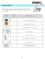
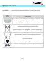
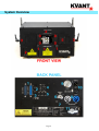
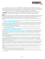
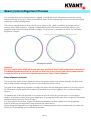
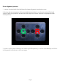
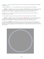
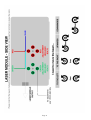
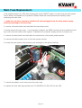
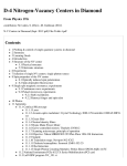
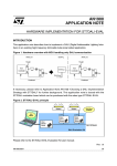
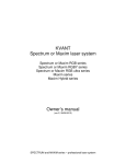
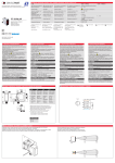
We give you the power of laser light.
MODEL SPECIFIC INFORMATION
KVANT ATOM 801
FULL COLOUR PURE DIODE LASER SYSTEM
© 2014 KVANT s.r.o.
All rights reserved.
Written by Martin Pelikan
Version 1.1
Thank you for purchasing a KVANT product.
To ensure proper operation, please read this Model Specific Information
carefully before using the product.
After reading it, keep it in a safe place for future reference.
KVANT gives you the power of laser light.
Contents
Item Checklist
p. 1
Optional Accessories
p. 2
System Overview
p. 3
Standard and Safety Features of the Laser System
p. 4, 5
Beam (colour) Alignment Process
p. 6 - 9
Main Fuse Replacement
p. 10
System Specification
p. 11
Item Checklist
Before starting, check that all the following items have been
included with your laser system. If anything is missing, contact
your supplier.
Product
picture
Number
of
units
Product details
1
Laser System KVANT ATOM 801
1
Emergency STOP remote
1
3-pin XLR Emergency STOP remote cable
1
AC power cable
1
Interlock connector
2
Set of Safety keys (4 keys in total)
1
ILDA signal cable
1
CD with Model Specific Information
and Instruction Manual
Page 1
Optional Accessories
Here is a list of accessories that are compatible with the ATOM 801 laser system.
Product
picture
Product details
SafeScan lens. Six different lenses are available. These lenses increase
the divergence of the laser beam when scanning downward into the
audience, helping to make the show safer.
Make sure you fully understand the laser safety before using your
laser with or without these lenses!
Adjustable attachment bracket for SafetyScan lens
3-pin XLR Emergency STOP remote cable - available in various lengths
up to 500 metres
ILDA signal cable - available in various lengths up to 200 meters
Set of spare Safety keys
DiscoScan 2.0 lens from Pangolin - extends scanning capability of the
system to 360°
Mounting bracket for DiscoScan lens 2.0
Page 2
System Overview
Page 3
Standard and Safety Features of the Laser System
The KVANT ATOM 801 is a full colour, pure diode laser system that was designed for professional
use. When operated correctly and in the right conditions the ATOM 801 is able to deliver a strong
performance in venues with up to 800 people capacity. This laser can display virtually any colour
within the basic RGB palette and its secondary mixed colours including white.
The system is air-cooled and designed so that there is no airflow going through the optical
compartment of the system. This ensures that all important optical parts of the system stay clean for
longer, keeping the maintenance time down to a minimum. This is a real advantage for all the
venues where lots of smoke or haze is used on a daily basis.
This laser is IP rated to IP54, meaning that it is splash-proof. It is however important to understand
that this system was designed for indoor use and therefore it must not be exposed to rain, snow or
excessive amounts of dust.
FRONT VIEW FEATURES
0. laser aperture window with four socket bolts. Undo these four socket bolts to remove the
aperture window if you need to clean it or to install the DiscoScan 2.0 lens.
1. aperture masking plate. This metal masking plate can be moved up and down when two
locking bolts are loosened. This is an extremely useful safety feature which gives you an option to
limit the bottom of the laser output area if necessary (for example if audience scanning needs to be
avoided). The masking plate can also be attached upside down if needed, using the two top holes
above the aperture window.
2. allen key in easily accessible front cover slot. This tool can be used for all user-allowed
servicing procedures.
3. u-Turn 360 attachment bracket. Especially developed attachment bracket allows you to
spin it 360 degrees around the laser body whilst it can also be locked in a desired position by two
small handles on its side. There's no need to use excessive force when locking the system in a
desired position because of the sophisticated locking mechanism.
4. laser emission indicator. When this indicator is lit up it means that the laser system is
ready to emit laser radiation as soon as it receives the instructions to do so from the control
software.
5. beam alignment mechanism. Under this small metal plate that is held in place by 4 socket
bolts you will find the beam alignment mechanism that is used for the beam alignment when
necessary.
REAR VIEW FEATURES
1. ILDA signal In/Out. Use the ILDA Input connector for plugging in your laser control
interface with the supplied ILDA cable. The ILDA Output connector can be used to daisy chain
more laser systems together when needed.
2. X & Y axis Invert. Use these two switches when the axis are required to be reversed. This
can be useful when projecting a text or graphics on a rear projection surface.
Page 4
3. ScanFail Safety indicator. This indicates the state of the scan-fail safety circuit or the
Emission Delay function. After every switch ON, this indicator will flash for about 60 seconds during
which the laser will not emit any laser radiation. After this initial period the light will turn itself off and
only light up again when there is a problem with the scanning system or input signal.
ScanFail mode selector. There are two modes in which the scan-fail circuit can work in:
SCANNER - the system controls the movement of both scanners. If there is no movement it
switches the laser emission off and keeps it off until there is a movement on both scanners
detected.
INPUT - the system checks for a difference between the input signal that goes into the laser system
and the movement of galvo motors. If the system detects that there's a difference between these
two signals (meaning that scanning system is faulty), it will switch the laser emission off.
Please note that in the INPUT mode the safety circuit sometimes kicks in if the scanned effect is too
small.
4. X & Y axis Size and Position. If necessary, you can these control pots to adjust the size
and position of the master projection zone.
5. colour adjustment pots. An output of each of three basic colours (RGB) can be manually
adjusted by turning corresponding pot to the left or right. Normally, all the colours are adjusted in
the laser control software and these pots are mainly used when taking measurements or when
performing the beam alignment procedure.
6. Safety key switch. The Safety key must be inserted and turned to ON position in order to
enable the system to operate.
7. Moncha.NET power connector. This is used to directly power supply the Moncha.NET
interface which can be purchased separately.
8 & 9. Main power socket IN/OUT and POWER switch. Use supplied power cable with the blue
Neutrik Powercon connector to connect the laser system to power supply. The main power switch
needs to be switched ON for the laser to be operational. The system requires 110-230V/50Hz
power supply.
There is also a power output connector (grey Powercon) which can be used for daisy-chaining of
more systems together for an easy installation. Please note that maximal number of laser systems
should not exceed 8 units.
10. E-STOP Remote connector and Interlock status indicator. In order to use the laser
system, the Interlock must be disabled. This can be done either by connecting the Emergency
STOP Remote to the 3-pin XLR INPUT Remote socket by using supplied cable or by plugging in the
supplied Interlock Connector.
Please note that it is a legal requirement to have a working E-STOP with every laser system and that
if you will use the Interlock connector for defeating the interlock you must have another method of
being able to switch the laser system off remotely in case of an emergency (i.e. electricity power
cut).
The Interlock status indicator goes off when the Interlock is defeated and the Interlock key is in ON
position. Unless all above is done correctly, the interlock will not allow laser emission from the
system.
The REMOTE Output is used to daisy-chain the Remote signal when you want to use a single
Emergency STOP Remote to control multiple systems.
11. Safety eyelet. Use this together with appropriate safety wire to secure the system against
unexpected fall.
Page 5
Beam (colour) Alignment Process
It is possible that due to transportation, rigging, moving around or vibrations caused by various
elements during a set up or laser performance, some of the internal optical parts can move slightly
resulting in colour misalignment.
The colour misalignment is when two or more colours (red, green and blue) physically do not
overlay each other properly - making it impossible to get nice mixed colours like yellow, cyan,
magenta and white (including all their shades). If this occurs it necessary to carry out the beam
alignment process.
Misaligned beams
Warning!
Be very careful when aligning beams and wear sufficient laser safety protection if necessary.
The beam alignment process is carried out when the front cover of the optical compartment
is open so there is a risk of accidental exposure to Class 4 laser radiation.
Beam alignment principle:
There are three laser colours (beams) within the system where one of them (usually the blue one)
has a fixed position aiming at the centre of the bottom scanner mirror.
The goal of the alignment process is to align the other two red and green beams to the first one so
all the beams overlay each other, making it possible to mix them together for a vivid and sharp
colours.
An easiest way to do this process is to project a full size circle so you can see it on the wall or
another projection surface during the alignment. That way you make sure that you get all the beams
aligned properly on both X and Y axes.
It is also good to know that, longer the distance between the laser system and the projection
surface is during the alignment, more precise the result will be.
When doing the alignment on long distances it is always good to have someone with you who can
direct you. Alternatively you could use binoculars.
Page 6
Beam alignment process:
1. remove 4 socket bolts that hold down the beam alignment mechanism cover.
2. the two adjustment groups will be revealed (picture below) - one for each colour (Red and
Green). Each group has four socket bolts that adjust the internal direction of appropriate laser
beam (colour).
3. power up the system following the Switching ON Sequence (p. 6 of the User Manual) and follow
the alignment instructions on the next page.
Page 7
4. create a cyan static tunnel effect (circle) so you can clearly see the whole shape on a projection
surface (i.e. wall).
5. check whether the green circle overlays the blue circle at all points around the shape.
IF not: use supplied 1.5mm allen key to adjust the GREEN adjustment socket bolts according
to the picture on next page, following the bolt numbers, turn directions and order in which the
adjustments need to be done, until the green circle sits exactly on top of the blue circle.
6. create a magenta static tunnel effect (circle) so you can clearly see the whole shape on a
projection surface (i.e. wall).
7. check whether the green circle overlays the blue circle at all points around the shape.
IF not: use supplied 1.5mm allen key to adjust the RED adjustment socket bolts according to
the picture on next page, following the bolt numbers, turn directions and order in which the
adjustments need to be done, until the red circle sits exactly on top of the blue circle.
8. finally create a white static tunnel effect (circle) so you can clearly see the whole shape on a
projection surface (i.e. wall). If you've done the alignment process successfully you should see all
the colours nicely overlaying each other resulting in even, bright and sharp circle like the one on the
picture below.
Page 8
Page 9
Main Fuse Replacement
If the system doesn't turn ON after pressing the main ON/OFF switch it is likely that the main power
fuse is blown and needs to be replaced. Please follow the instructions below carefully when
replacing the main fuse.
1. make sure the laser system is switched off and unplugged from the main power supply
before proceeding to the next step.
2. remove 18 socket bolts that hold down the top metal cover.
3. slowly remove the top cover - it is necessary to detach the GND connector that is attached to the
top cover from the inside of the system. To detach the connector simply pull the connector out.
4. remove 4 socket bolts that hold down the metal cover of the main power section.
5. remove the black metal cover of the main power section.
6. locate the main power fuse position (red rectangle on the picture below).
7. remove the plastic cover that covers the main fuse.
8. replace the fuse with appropriate fuse T3.15A/250V (T 6.3A/110V for the US).
Page 10
System Specification
KVANT ATOM 801 - full colour pure diode laser system
Total Optical Power (installed):
930mW
Total Optical Power (guaranteed): 800mW
Red:
Green:
Blue:
170mW / 637nm
110mW / 520nm
650mW / 445nm
NOHD (Nominal Ocular Hazard Distance): 275m
Beam diameter at laser aperture: 3mm
Beam divergence: <0.72mrad (full angle)
Modulation: 0-5V analog, up to 50kHz
Module cooling: TEC
Scanning System:
ScannerMAX 506 Compact, 35kpps @ 8°, max. scanning angle 60° on both axes
Control signal input: ILDA-IN DB25 male
Control signal output: ILDA-OUT DB25 female
Power requirements: 100-240V/50Hz (±5%)
Consumption: 250VA/100-240V
Operation temperature: 10-40°C
Ingress protection rating: IP54
Dimensions (WxDxH): 256 x 152 x 168mm
Weight: 5.7kg
Integrated Laser Safety features: Keyed interlock, emission delay, magnetic interlock (when housing cover is off),
adjustable masking plate, ScanFail circuit + mechanical shutter (reaction time < 20ms).
Page 11