1
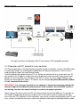
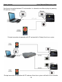
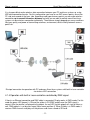
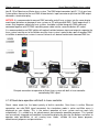
KVANT
Spectrum or Maxim laser system
Spectrum or Maxim RGB series
Spectrum or Maxim RGBY series
Spectrum or Maxim RGB ultra series
Maxim series
Maxim Hybrid series
Owner’s manual
(rev.D, 03/07/2012)
SPECTRUM and MAXIM series – professional laser system
Owner’s manual
Kvant Spectrum/Maxim laser system
Thank you for purchasing this KVANT product!
To ensure proper and safe operation, please read entire owner’s manual carefully before using the
product. After reading it, keep it in a safe place for future reference.
TABLE OF CONTENTS
-2-
Owner’s manual
Kvant Spectrum/Maxim laser system
1. LASER SAFETY INFORMATIONS, CAUTIONS AND WARNINGS
1.1 IMPORTANT INFORMATIONS ABOUT LASER LIGHT
The laser light is extraordinary type of light. It is much more concentrated than light from any other
light sources. This high concentration of light can cause permanent eye injuries if eyes are exposed
to the laser light. If the laser beam power reach certain level, it is possible to feel the “power” at skin
like heating or burning. This varies of the laser wavelength and applied power.
Please note that also laser beams that are not as powerful as “heating or burning” beams can cause
fatal eye injuries.
Please note that also scanned and moving laser beams can be dangerous too and can cause fatal
eye injuries.
Please note that also individual laser beam from larger picture which represents only a fragment of
total output power can be potentially dangerous for eyes.
1.2 LASER SAFETY CAUTIONS AND WARNINGS
CAUTION:
Visible and invisible laser radiation. Avoid eye and skin exposure to direct or scattered
radiation! Class IV. laser product EN 60825-1 : 2007
CAUTION:
By using other controls or adjustments than described in this manual, you can expose
yourself or other people to dangerous laser radiation. This laser product can potentially cause
fatal or total eye injury if eye is stroked by laser beam.
CAUTION:
It is forbidden to allow projecting the beams to the audience and any areas accessible by
persons without appropriate eye and skin protective items. For eye protection use suitable
eye protective spectacles if working in front of system (in scanning area) or maintaining the
system with opened covers. Use spectacles with minimum optical density 190-400nm OD5+,
510nm-670nm OD1.5+ 2%VLT
CAUTION:
Always install the output window of your laser system minimum 3m above the floor level
where audience or public are located. Make sure that any laser beam is projected below this
level.
CAUTION:
It is forbidden to shine any laser beam to the aircrafts.
-3-
Owner’s manual
Kvant Spectrum/Maxim laser system
CAUTION:
Risk of fire or burning materials. Keep flammamble materials far from the system. Do not
shine to any flammamble liquids or materials (e.g. paper, curtains...) with laser beams at short
distances where the beam can heat up the flammamble surfaces.
WARNING:
The KVANT SPECTRUM OR MAXIM laser system is a laser product class IV. It can be operated
only by qualified personnel by regulatory body or authorized training organization. If the laser
is operated in a situation where health or property injury may occur, operation MUST be
stopped immediately!
Manufacturer and distributors are not responsible for any damages caused by use of KVANT
Spectrum or Maxim lasers. User is responsible for applying conditions of use according to
regulations stipulated in EN60825-1:2007 and all locally applicable safety laws and
regulations.
1.3 WARNING SIGNS
2. GENERAL SAFETY INSTRUCTIONS, CAUTIONS AND WARNINGS
2.1 GENERAL SAFETY INSTRUCTIONS
This device can be installed, maintained, checked and opened by qualified personnel only. If you are
not qualified, please ask your distributor for such operations.
Before the installation read all instructions and warnings in this owner’s manual.
-4-
Owner’s manual
Kvant Spectrum/Maxim laser system
The laser system is sensitive to shaking and rough handling. It is recommended to use the supplied
flight case. Ensure the soft foam internal packing (5cm min thickness) is in place on all faces.
Correct packing allows the laser system to “float” slightly inside of the closed flight case. This
prevents vibrations and shocks being transferred directly to the laser system.
Before you install the system make sure that power voltage is not higher than maximal input voltage
of the laser system. For replacement please use fuses of the same type and rating only. Never
connect the Spectrum or Maxim’s AC plug to output of any dimmer. Connect it directly to power plug.
Always plug the power cable as the last step of installation process. Make sure that the main power
switch is in OFF position while connecting the power cord into mains. Always disconnect the device
from mains before maintenance or cleaning. Always perform the disconnection of the laser system
from mains by pulling the power cable from the mains socket. The power cable must be therefore
easily accessible.
The system must never be exposed to dripping or spraying water and objects containing liquids (e.g.
vase) are not allowed to be placed on top of the system.
If the device has been exposed to larger temperature changes (e.g. during transport), do not turn it on
immediately. The water condensation can damage the system. Keep your system turned off till it
reaches the ambient temperature.
The ambient temperature must be between 10°C (50°F) and 35°C (95° F). Do not use the fixture if
ambient temperature is above 35°C (95°F) or below 10°C (50°F), if relative humidity exceeds 90%, or
if condensation is forming.
Always stop operation if the output window is broken or missing. Before next operation replace the
output window with suitable replacement or contact your distributor.
Always fix the device with suitable lighting safety cable when hanging the laser system overhead.
Make sure that the construction you are going to use for installation of laser system is enough safe to
carry 5 times more than total weight of all installed items.
2.2 GENERAL SAFETY CAUTIONS AND WARNINGS
CAUTION:
Risk of electric shock. Do not open the device. Do not operate the laser system if any covers
are open, missing or damaged.
CAUTION:
Do not allow to operate this laser system by unauthorized personnel for laser system
operation. Operate the system only after reading and understanding all it’s functions. Never
remove safety or warning stickers from the laser system housing.
CAUTION:
-5-
Owner’s manual
Kvant Spectrum/Maxim laser system
Risk of finger injury. Do neither put fingers, nor any other objects into fans, fan holes or their
covers.
WARNING:
Make sure that there are no heat-producing device installed near to the laser system and keep
free area around the system of minimum 40cm from each side to ensure proper cooling
conditions.
3. DESCRIPTION OF KVANT LASER SYSTEM.
3.1 GENERAL DESCRIPTION
Kvant Spectrum or Maxim is professional laser system with wide range of use, mainly for laser show,
entertainment and advertisement as well.
Kvant Spectrum or Maxim laser projector is possible to control with following controlling modes:
- Controlling with any ILDA compatible software connected via ILDA signal input
- Controlling with installed software Display connected with laser system’s build in Laser controller
(optional) via ethernet cable connection
- DMX controlling of build in controller that contains at its SD memory card various preprogrammed
shows, patterns and animations (up to 32GB)
- Stand-alone operation, playback of selected show/pattern/animation
Spectrum or Maxim laser system has several internal protections including scan fail safety system,
multiple interlock system and remote controller with indicators and safety stop button.
Spectrum or Maxim laser system is manufactured with IP 44 housing (expect rear panel) that can be
used also for temporary outdoor installations (outdoor concerts or events). It is not suitable for
permanent outdoor installation. In that case the system has to be installed into additional housing to
protect the laser system. The additional housing is available on request.
3.2 FEATURES
Mechanical:
Dimensions (W x D x H):
Dimensions with handle:
Weight:
see product datasheet (model specific)
see product datasheet (model specific)
see product datasheet (model specific)
Electrical:
Input voltage (full range): 100-240 VAC, 47-63Hz
Current consumption:
see product datasheet (model specific)
Optical:
Total output power*:
Laser module specs.:
Laser class:
Laser operation:
see product datasheet (model specific)
see product datasheet (model specific)
4
CW (continuous wave)
Scanning:
Scanning input signal:
+-10V/ ballanced
-6-
Owner’s manual
Kvant Spectrum/Maxim laser system
Scanning system
LM
Scanning angle
Scanrate for 3mm beam [kpps] **
Scanrate for 5mm beam [kpps] **
Scanrate for 5.5mm beam [kpps] **
60° x 60°
27
-
CT 6215
Kvant drivers
60° x 60°
36
30
29
CT 6215
CT HP drivers
60° x 60°
55
35
33
Connectors:
AC power:
ILDA IN / OUT:
DMX IN / OUT:
Remote controller:
Ethernet:
SD card slot:
Powercon Neutrik
Sub-D 25pin – male (1x) / Sub-D 25pin – female (1x)
XLR 5pin –male (1x) / XLR 5pin –female (1x)
Sub-D 9pin – female (1x)
RJ45 (1x)
(1x)
Safety:
Scan fail system:
Interlock for covers:
Safety key switch:
Horizontal adjustable
bottom limiter:
Yes
Yes, top cover
Yes
Temperature:
Yes
Ambient temperature:
0 - 45°C (32 – 113°F), not condensating
Ambient operation temperature: 10 – 35°C (50 - 95°F), not condensating
* = Nominal output power measured before the scanners inside of the system.
** = Measured at ILDA12/30k test pattern at size 8%. Internal circle is touching square at all four sides.
4. OPERATION OF KVANT LASER SYSTEM
4.1 TYPICAL MODELS OF CONTROLL THE LASER SYSTEM.
4.1.1 Operation with PC and PCI card ILDA compatible controller.
WARNING: PC and all laser systems MUST be connected to the same plug to avoid signal
distortion or damage of laser systems or PC with possible GND / Earth loop current. It means
that the power cable from laser systems should be installed along with ILDA cable and
connected together with PC power cable into THE SAME distribution AC socket.
NOTICE: Always use original ILDA cables for ILDA signal connection. Using different cables than
original can cause incorrect operation of laser system or can damage the laser controller.
-7-
Owner’s manual
Kvant Spectrum/Maxim laser system
Principal connection for operation with PC and PCI card ILDA compatible controller
4.1.2 Operation with PC and external ILDA compatible controller (USB or Ethernet).
WARNING: PC and all laser systems MUST be connected to the same plug once the external
ILDA controller use USB data connection to avoid signal distortion or damage of laser
systems or PC with possible GND / Earth loop current. It means that the power cable from
laser systems should be installed along with ILDA cable and connected together with PC
power cable into the same distribution AC socket.
NOTICE: Always use original ILDA cables for ILDA signal connection. Using different cables than
original can cause wrong operation of laser system or can damage the laser controller.
For Ethernet connection between PC and external ILDA compatible controller it is allowed to use
different plugs for powering PC and laser systems.
-8-
Owner’s manual
Kvant Spectrum/Maxim laser system
Principal connection for Operation with PC and external ILDA compatible controller
4.1.3 Operation with PC and built-in Laser controller.
The Ethernet operation is the highest priority operation of built-in controller. It means that DMX mode
or stand-alone modes are automatically disabled once the Ethernet connection is active. For this
mode the display shows message Ethernet mode.
Install the Moncha.Net software to your PC first. Before you connect the laser system with your PC,
you should set the IP address of your laser on its display main menu manually (main menu screen,
position 3), Laser controller uses IP address 192.168.1.X, where X is from range 0-255 and every
device must have original IP address. IP address can be changed only when Moncha.Net software
is *not* connected to the device.
IMPORTANT: It is necessary to select in your computer’s Local area connection settings the
manual IP address according the address preset in the controller. Here the DHCP service is
not working, therefore the manual settings is necessary for proper operation.
Always connect the laser system with PC via Ethernet cable shorter than 1000 feet. It is possible to
use straight-through cable or crossover cable as well. If you want or control simultaneously more
lasers from one PC using built-in Laser controllers, you have to use data switch between your PC and
laser systems and connect each laser system with one data switch port via individual ethernet cable.
-9-
Owner’s manual
Kvant Spectrum/Maxim laser system
For ethernet connection between PC and controller it is allowed to use different plugs for powering
PC and laser systems.
Principal connection for operation with PC and one built-in Display Kvant laser system
Principal connection for operation with PC and more Kvant laser systems with built-in laser controller
- 10 -
Owner’s manual
Kvant Spectrum/Maxim laser system
It is also possible to make wireless data connection between your PC and laser system e.g. using
WiFi data connection/transfer. For this configuration you have to use WiFi access points, one at the
PC side and second at the laser side. According used type of access points you can make wireless
connection up to several kilometers distance and also you are able to control more Kvant laser
systems via one wireless connection individually. The distance strongly depends on many conditions
like type, quality and power of transmitting antennas, environment, direct visibility between access
points etc.
Principal connection for operation with PC and more Kvant laser systems with built-in laser controller
via wireless WiFi connection
4.1.4 Operation with built-in Laser controller controlled by DMX signal.
If there’s no Ethernet connection and DMX cable is connected, Display works in DMX mode. For this
mode the green LED (power) is ON and the yellow is ON (DMX mode) once the DMX signal is
correct. After the picture is displayed to the output, the red LED (active output) will start to flicker as
well. DMX address is set by main menu (Main menu, position 4). When Display is in DMX mode, it
receives DMX channels and plays all the pictures and shows stored at SD-card.
- 11 -
Owner’s manual
Kvant Spectrum/Maxim laser system
DMX signal controlling principles
The DMX address selected at Laser controller is the number of “first” channel used to receive valid
control data within the range of 512 channels available in one DMX channel packet. Laser controller
use 17 channels for full controlling abilities, it means that group of 17 channels in a row will control
the controller. If e.g. the DMX address preset in Laser controller is 16, then the physical data from 16
to 33 will control all parameters in DMX operation mode of Display. To avoid unexpected behavior,
make sure that channels used by different DMX devices are valid just for the selected device and are
not overlap for more devices.
Allow enough channels for the controller out of the 512 available. If the controller is set up to use 17
channels, for example, the highest value you should set as DMX address is the first of those 17
channels, i.e. 495. If you select the same address at more laser systems, you can simultaneously
perform the same steps on each laser.
Display channel assignment:
CH.#
1
2
3
4
5
6
7
8
9
10
11
12
13
14
15
16
17
Function
Position X
Position Y
Rotation
Size X
Size Y
Brightness
Scanrate
Animation
Animation speed
Animation
direction
Red
Green
Blue
Dark Blue
Position X fine
Position Y fine
Rotation fine
Details
128 – position in the middle
128 – position in the middle
0…0 degree, 255…360 deg.of rotation
(0%) – 255 (100%)
(0%) – 255 (100%)
(0%) – 255 (100%)
0 (default), 1 (slowest) – 255 (fastest)
0 (none), 1 – 255 (animation from SD-card)
0 (0% - stop) – 128 (100%) – 255 (300%)
0 – 127 (normal direction), 128 – 255 (opposite) – this
is working only for files up to 255 frames
0 – default, 1 (0%) – 255 (100%)
0 – default, 1 (0%) – 255 (100%)
0 – default, 1 (0%) – 255 (100%)
0 – default, 1 (0%) – 255 (100%)
Fine position for X
Fine position for Y
Fine rotation
Connecting to a DMX installation
The build in Laser controller has two DMX connectors XLR 5-pin type (pict B, 10&11), wired with pin 1
to ground, pin 2 to negative signal (-) and pin 3 to positive signal (+). This is the standard
configuration for DMX devices. Pins 4 and 5 are not used.
You can connect up to 32 devices to one DMX line and you can use up to 1km total distance between
transmitter and the last DMX device. Always terminate the DMX line by inserting a 5-pin XLR male
termination plug into the data output of the last DMX device. The termination plug is standard XLR
connector with a 120 Ohm, 0.25 W resistor soldered across pins 2 and 3.
Before you connect the DMX data cable into Spectrum or Maxim DMX input connector (pict B, 10),
please turn off all running DMX devices connected to the same DMX data cable. Connect the DMX
output connector of your DMX console (DMX transmitter) with DMX cable to the DMX input connector
- 12 -
Owner’s manual
Kvant Spectrum/Maxim laser system
(pict B, 10) of Spectrum or Maxim laser system. The DMX output connector (pict B, 11) of your laser
system please connect to the next DMX related device’s input connector or put into the DMX output
connector a termination plug.
NOTICE: It is recommended to connect DMX controller and all laser systems into the same plug to
avoid signal distortion or damage of laser systems or PC with possible GND / Earth loop current. It
means that the power cable from laser systems should be installed along with DMX cable and
connected together with PC/DMX controller power cable into the same distribution AC socket.
It is recommended to use DMX splitter with optical isolation between input and output to separate the
laser system from the rest of installation once the laser system is going to be a part of complex DMX
installation to protect laser system in case of failure of any device connected to common DMX line.
Principal connection for operation of Kvant laser system with built-in laser controller
controlled by DMX signal
4.1.5 Stand-alone operation with built-in Laser controller.
Stand –alone mode has the lowest priority of built-in controller. Once there is neither Ethernet
connection, nor valid DMX signal connected, the stand-alone mode is active and Main menu is
displayed on your display. This is the easiest operation of laser system and can work fully
automatically. It is suitable e.g. for advertisement and automatic operation purposes. This function
can be manually triggered and modified via controlling display by pressing the buttons and offers to
operator wide possibilities of self running laser shows, suitable for laser demo purposes,
advertisement purposes and presentations.
- 13 -
Owner’s manual
Kvant Spectrum/Maxim laser system
This is basic screen for stand-alone mode:
You can use up and down buttons to select file to play from SD-card (up to 255 files). With right
button you can display main menu. Main menu contains 9 items. List of main menu items is bellow.
Draw settings
Default file
IP Address
DMX Address
Display test
Load settings
Save settings
Reset settings
About …
Allows you to display draw settings for Stand-alone mode (Size, Position, …)
Sets default file, which will start to play after Display is turned on with stand-alone mode.
Set IP address of the device
Set DMX address of the device
Displays single white beam at the laser output
Loads Stand-alone mode settings from internal memory
Store stand-alone mode settings into device internal memory
Reset settings to default state
Display basic information about Display device (Version, Run hours, Serial number, …)
You can select specific settings using right button. Laser controller has internal memory, where it can
store all Draw settings, Default file, IP and DMX address. You can Load/Save/Reset these settings
using menu commands. You can select in “Draw settings” sub-menu following parameters for standalone mode:
Size X
Size Y
Position X
Position Y
Rotation
Scan-rate
Animation speed
Color
Repeat
Invert X,Y
Set horizontal size
Set vertical size
Horizontal position
Vertical position
Rotate picture around depth axis (Z), it’s practical when laser is placed on tilted surface
Set scan-rate for the images:
0-default scan-rate, 1-1% of required scan-rate, 255-100% of required scan-rate
Speed of played animation:
0-Stop, 128 – 100% speed, 255 – 300% speed
Allows you to recolor whole image using one color
If checked, played animation or show is repeated when it ends
Flip horizontally or vertically the displayed pictures
Principal connection of stand-alone laser system is very simple – just plug your Kvant laser system
into AC power plug. That’s it.
- 14 -
Owner’s manual
Kvant Spectrum/Maxim laser system
NOTICE: Master settings of size, color, position etc. for stand-alone mode are stored in
autoplay.txt file. It can be easily modified with any text editing program. Once the autoplay.txt
is saved in root SD card directory, the presets are loaded each time the laser system is
operated in stand-alone mode.
Autoplay.txt file is usually saved in AUTOPLAY directory together with readme.txt where this feature
is explained as well. The autoplay.txt file must be copied into SD card’s root directory if user wants to
use the autoplay.txt features (mainly for stand–alone advertisement automatic player purposes). This
autoplay.txt file can be changed remotely and whole laser system can be controlled remotely via
internet. There must be allocated by the provider at least one solid IP address for each built-in laser
controller. Laser system should be connected via router to ensure at least certain firewall protection.
This way you can easily upload the shows, pictures and animations to your SD card and also you can
modify all the system files at your SD card via INTERNET, even update the firmware so there is no
need to go personally to your laser system for upload / updates anymore.
Principal connection of remotely controlled laser system via Internet connection
- 15 -
Owner’s manual
Kvant Spectrum/Maxim laser system
4.2 TURNING ON SEQUENCE.
WARNING: Turn the system ON only if all Laser safety and general safety warnings and
cautions are understood and fulfilled. For more information please refer to chapter 1 of this
owner’s manual.
WARNING: Before you turn the unit ON, please make sure that the RGB test output switch is in
OFF position (for Laser controller option included in controller’s menu) and the scan-fail system
enable switch is in ON position to avoid uncontrolled dangerous operation of laser system.
1. Connect laser system Spectrum or Maxim according one of operating model schematic diagrams
(see chapter 4.1)
2. Select the scan-fail system mode by scan-fail mode switch (pict B, 6) For more info please refer to
chapter 6.
3. Release the aperture window fixing bolts (pict A, 5) and slide the aperture window front cover (pict
A, 4) to bottom - fully opened position.
4. If your system is not equipped by remote controller, please go to step 7
5. Connect the remote controller to the remote controller connector (pict B, 7). Ensure that the stop
button of remote controller is in released upper position. There is red LED near to the remote
controller, that is shinning always if either remote controller is blocked or it is not connected. It
shines also when any of magnetic interlock switches is not closed (e.g. while opened laser cover).
6. Insert the safety key into the remote controller safety key switch (pict C,2) Turn it to ON position.
Safety key is removable only in OFF position.
7. Insert the safety key into safety key switch (pict B,4). Turn it to ON position. Safety key is
removable only in OFF position.
8. Switch ON the laser system with mains switch (pict B,2). The mains switch will start to illuminate in
red.
9. The status indicator (pict B,18) will start to blink in regular period during startup delay of either 15
sec or 1 min depending on local country safety regulations. During this period is blocked possible
laser emission and laser modules are heating up.
10. After the startup delay finish, the emission indicator (pict A,6) will illuminate and laser emission is
enabled. The status indicator will stop to shine. The laser modules will reach full power after their
complete thermal stabilization which can take up to 3-5 minutes from switching on the system.
This time depends on ambient temperature and initial temperature of laser system.
11. Now you can start the projection from your software / laser controller.
12. You can adjust the color balance with brightness controls (pict B,13) or via the built-in laser
controller menu.
13. It is possible to run the test mode of your laser system either by selecting the “Display test” of
Laser controller Menu or switching the test switch to ON position (pict B,20).
14. You can invert the axes by pressing the arrow buttons of Laser controller and you can save it into
menu as default in “Draw settings” of built-in Laser controller Menu. Once your system isn’t
equipped by Laser controller, then you can invert the axes by Invert axes switches (pict B,19).
15. For Maxim and Maxim Hybrid models you can select the source of blanking signal for dominant
color of your laser system by TTL/Analog switch (pict B,17).
16. For RGB30/35W and RGB ultra systems you can select the source of blanking signal for the dark
red colour 658nm with the red input selector (pictB,21). For 637+658nm you control both red
wavelengths together from red colour output and for individual driving the dark red colour is
controlled via signal connected to “dark blue” output, (ILDA, pins 8&22). This way you can make
- 16 -
Owner’s manual
Kvant Spectrum/Maxim laser system
interesting colour mixing with two red colours included in your laser system. Also all pictures /
shows stored in built-in laser controller can be modified to four colour version easily.
17. If any dangerous situation occurs, immediately turn off the laser system with the mains power
switch (pict B, 2) or by pressing the emergency stop button (pict C, 1) or disconnect the main
power cable.
IMPORTANT: For analog option (Maxim and Maxim Hybrid models only) takes your system
blanking signal from dominant color output (for green = ILDA, pin 6, for blue =
ILDA, pin 7) and you can fade brightness level of your laser by software. Then
you can see ONLY parts of picture that contains the dominant (green or blue)
color.
For TTL option your system takes the blanking signal from TTL output of your
controller (ILDA, pin3) and your system will not perform fading of brightness.
For TTL option will be visible ALL parts and colours of displayed picture with
full brightness.
4.3 TURNING OFF SEQUENCE.
1. Stop the projection in your software / laser controller
2. Turn to OFF position both remote controller key switch (pict C, 2) and rear panel safety key switch
(pict B, 4) and remove the keys. Store them at safe place for next operation.
3. Allow at least 1 min cooling down period, before switching OFF
4. Turn the mains switch (pict B, 2) to OFF position.
5. BUILT-IN LASER CONTROLLER
Built-in laser controller is professional laser show controller. Your Kvant laser system can be used
with three different modes: PC controlled software for live lasershow purposes (software is included),
DMX operated lasershow controller and stand-alone controller for playback of ready patterns or whole
laser shows. All pictures and shows (for the DMX and Stand-alone mode) are stored in the SD-Card,
that supports FAT and also FAT32 file system with maximal capacity up to 32GB.
The main three modes of operation are described in details in chapters 4.1.3 - 4.1.5. There are three
useful features included in Laser controller that enhance possibilities of use and get maximum
performance of Spectrum or Maxim laser system.
IMPORTANT: All of following three functions are defined by separate text files [*.txt] with exact
file name format. They must be saved in SD card’s main root directory.
5.1 BRIGHTNESS MAPS
You can define brightness maps, i.e. sub areas within whole scanning area (60°x60° degrees optical)
with predefined reduced brightness level. For the brightness cut-down is used number between 0100. It means you define the percentage of original brightness level for each point (part of picture) in
the brightness map. The brightness map is great to ensure protection of audience or that part of
scanning area where the possible audience can occur.
- 17 -
Owner’s manual
Kvant Spectrum/Maxim laser system
IMPORTANT: Brightness map is useful tool to make your DMX OPERATED LASER SHOW
SAFE as the brightness map is master and it doesn’t depend on any other
settings like position or size.
There can be defined up to 8 independent sub areas and they are defined in map.txt file. Each sub
area can have rectangular shape with defined left, right, top and bottom border and selected
brightness level definition. In case of more sub areas write all of them into one file, separate individual
sub area definitions only with one empty row.
Either left or right border of sub area can have value from -100 up to 100 what represents -100% up
to 100% of X axes excursion. It means -100 represents fully left border of scanned area and +100
represents fully right border of scanning area. Either bottom or top border of sub area can have value
from -100 up to 100 what represents -100% up to 100% of Y axes excursion. It means -100
represents fully bottom border of scanned area and +100 represents fully top border of scanning
area.
Two ways of brightness level definition are available. Either the brightness level can be constant
value for whole sub area or the brightness level can be defined for the borders (top bottom, left and
right) of sub area and Display will automatically calculate smooth fade of the brightness for each part
of that sub area according the border brightness level.
For constant brightness level within a sub area write to the map.txt only 4 border position and simply
Brightness = x , where x is desired brightness decreasing percentage (0-100).
For smooth fade of brightness sub area you should define the borders and also border brightness
levels. On the left side you can see an example of such map.txt file and on the right side you can see
corresponding brightness decreasing level within specified sub area from example.
All the files must be stored in card’s root directory! You can use ‘;’ to make notes in the files – all the
text behind ‘;’ is ignored. This is useful to apply once you want to make the difference between file
versions or for backup purposes as the file name must always stay the same.
- 18 -
Owner’s manual
Kvant Spectrum/Maxim laser system
5.2 CONFIGURE COLOR BALLANCE
Use balance.txt file to define color balance of the colors. There are 7 colors used: White, Red,
Green, Blue, Magenta, Cyan and Yellow and you can define color channel levels (levels of the RED,
GREEN, BLUE and DARK BLUE outputs) for every one of these colors. So e.g. for RGV laser (the
one with red, green and ultra-violet 405nm lasers), it is good to add a little green color to the blue (it
will look more like blue).
5.3 CONFIGURE COLOUR FADES
Sometimes a laser module turns on at e.g. 30% of the fade range and is at maximal brightness at e.g.
60% of the fade range. This is usually possible to see at green modules that are DPSS type and their
output power can be nonlinear in order to laser diode current. Then it’s good to change color fade
curves to enhance color fade. Linear fade curve is defined by two points, beginning and ending point.
If the fade curve has more parts (it is not a straight line) then you have to add points, where the curve
should changed its tilt. The point definition has following format: Point=A,B where number A is desired
value of brightness (0 means 0% and 255 represents 100%) and B represent output of controller,
when the module gives corresponding brightness to desired value (0 means 0% and 255 represents
100%). For each color can be defined different fade curve. All fade curves must be saved in fades.txt
file. Example is below.
For example if the green module
turns on 30% of input blanking
voltage and reach full power at
70% of input blanking voltage,
then it is possible to correct it by
following fades.txt file.
On the left side you can see the
standard fades.txt file, all four
colour outputs have linear curves.
If we write for green colour the
text according right picture, then
green will get 30% of brightness
input voltage at 0.3% of desired
brightness level (when this
module starts to shine) and will
get 70% of brightness
input
voltage range (where the module
reach already the maximal output
power) at 98% of desired
brightness level.
- 19 -
Owner’s manual
Kvant Spectrum/Maxim laser system
5.4. UPLOADING ANIMATIONS TO
LASER CONTROLLER
You can create and upload frames to Display
SD-Card using Display software. It is even
possible to upload to more devices at once,
which is very practical by DMX-controlled laser
shows.
Thanks to brightness maps it is even possible
to make the DMX laser show safe. You can
find upload scenes dialog in Tools->Upload
scenes in Display software menu. Following
window will be displayed:
On the left side you can see animations, which will be exported to SD-Card. You can change
animation to any scene from your workspace. Just select Choose Scene and you’ll be able to pick
any scene from workspace.
The remaining settings can be used to prepare your animation suitable for DMX control. Start Time
sets start time of the animation, End Time end of the animation. Using these settings you can make
your animation loop-able.
Number of frames determines number of frames of the exported animation. It is recommended to use
less than 256 frames – like this you’ll be able to control direction of the animation (using channel 10).
Frames per seconds determine speed of playing of the frames. We recommend keeping it at 35, like
this the animation is smooth. When you set all your desired animations, you can export your scenes
to SD-Card or to Display devices directly. You can also export all animations or only one.
5.5 UPGRADING CONTROLLER FIRMWARE
Before you start to upgrade the built-in laser controller firmware, please take a SD card, insert into
card reader of your PC and perform format of your SD card using FAT 32 (!) file system. To upgrade
follow these steps:
1. Turn off your Display device.
2. Copy the file “mnet.bin” and bootldr.cfg to your FAT32 formatted card.
3. Insert the card into Display.
4. Turn on Kvant laser system. Upgrade will take less than 30 seconds.
- 20 -
Owner’s manual
Kvant Spectrum/Maxim laser system
6. SCAN-FAIL SAFETY CARD
Every KVANT laser system is equipped with a special electronic circuit that monitors signals going in
and out of the scanning system. In case of a failure/disconnection of one of the scanning components
or detected stable position of any scanner for longer than 20ms (50ms respectively), it disables the
brightness circuits of all used laser modules and the system’s emission is switched OFF immediately.
This kind of safety device is required by law in every EU/ECC country an in the U.S. included.
6.1 BRIEF DESCRIPTION AND OPERATION
1. After power on and initialization (factory programmed to 15sec or 1 minute), the Safe Card starts
monitoring signals at its axes inputs. Under normal conditions, the feedback signal coming from
scanner drivers is copying the input signal coming from ILDA input. Fault is defined as low
amplitude feedback (scanner not moving sufficiently), or no feedback signal at all (blown fuse, or
scanner disconnected).
2. According to selected mode of operation, it is monitoring either feedback signal movement only
(Mode switch in position SCANNER), or also input signals (Mode switch in position INPUT).
IMPORTANT: After any change of mode switch (SCANNER- INPUT) please restart the laser
system. Scan-fail safety card load the mode switch position only during
starting the system.
Scan-fail safety card layout
- 21 -
Owner’s manual
Kvant Spectrum/Maxim laser system
3. If there is mode switch in position SCANNER = no movement of feedback signals, the Safe card
disables laser output by switching output optocouplers off. Note that this also includes beam
positions, and horizontal/vertical lines only – laser output will be stopped.
4. If there is mode switch in position INPUT = no movement of feedback signals and while input is
moving, the Safe Card switches laser output off. You can display output beam positions, as well
as horizontal/vertical lines, with this mode. Your responsibility is to ensure, that no beam position
can be projected into the audience.
5. User can adjust sensitivity of scan–fail safety card i.e. amplitude of input signals that are
considered as small and “fault status”, by turning LEVEL trimpot cw: sensitivity higher, ccw:
sensitivity lower.
Sensitivity higher means smaller signals (pictures) are already a fault. Sensitivity lower means
larger signals (pictures) are already considered as a fault.
6. After fault condition is cleared, the Scan-fail safety card switches ON the laser output with a delay,
which is mode-dependant: scanner mode = no delay, immediately. For Input mode is the output
turned on with 1000ms delay.
7. User can disable Safe Card unconditionally by turning the scan-fail enable switch to OFF position.
In this case, the laser outputs are always enabled, even if fault condition exists.
IMPORTANT: It is STRONGLY RECOMMENDED to operate laser system with enabled scan
fail safety card. Do not operate it with disabled safety card as there is no
protection.
8. The EMISSION LED is on, every time, when there is possibility of laser output. It is mounted on
user-visible place of the front panel (pictA,6), near to the output window.
9. For laser emission to be possible, all INTERLOCK inputs must be shorted, the safety key must be
switched to ON position and all interlocked covers closed.
6.2 SENSITIVITY ADJUSTMENTS
1.
2.
3.
4.
5.
Select INPUT at scan-fail mode switch.
Pre-adjust sensitivity by fully turning LEVEL trimpot cw (maximum sensitivity).
All interlocks must be closed for proper operation.
Power on the laser system.
The safe card starts working, you can test it, for example by disconnecting any of the scanners, it
must disable laser outputs.
6. Play your show. The laser output must not be stopped when scanners are operating correctly.
When this happens and show is stopped sometimes, you have to decrease sensitivity by turning
LEVEL trimpot ccw.
7. CORRECT USE OF SCANNING SYSTEM
IMPORTANT: Warranty for scanning system does not include damages caused by improper
use of scanning system or improper replacement of scanner fuses. Therefore
please read carefully and apply following information.
- 22 -
Owner’s manual
Kvant Spectrum/Maxim laser system
The laser beams generated by laser modules are reflected by two moving mirrors one for horizontal,
second for vertical movement. These mirrors are mounted on scanner shafts and they are moved by
the scanner’s rotors. The drawing (image) is mechanically performed in real time. This kind of
drawing has maximum scan rate defined by mechanical load, mirror size/weight, complexity of
displayed picture, size and angle of projection. Each scanning system has different value of this limit.
It is always necessary to operate the scanning system at scan rates below the maximum scan rate.
7.1 HOW TO RECOGNIZE THE MAXIMUM SCAN RATE?
At the beginning it is necessary to understand that each picture has different value of maximum
scan rate, because each picture can contain different number of points. The more points the
picture contains, the lower maximum scan rate you can set. The best way to recognize this limit is to
observe the picture which is displayed by the laser system.
Choose a static effect and start to increase the scan rate in your software from minimum to higher
values.
IMPORTANT: The maximum scan rate is a when the displayed picture does not have distorted
shape around corner points. The maximum scan rate is exceeded when the
displayed picture shape begins to distort around corner points while increasing
the scan rate.
If you increase the scanning angle (size of projected picture), scanning speed needs to be lowered
accordingly. Scanning speed of LM scanning system is usually defined as 27 kpps (“kpps” means
Kilo Points Per Second). This number specifies only, how fast can be displayed the reference picture
“ILDA TEST 12/30k” at good shape conditions (8 degrees scanning angle and while internal circle is
touching the internal square). It is neither the maximal scan rate of LM scanning system, nor this
number 27kpps say that e.g. 1000 point picture can be displayed 27 times per second.
You can see examples of changing the scan rate for the same Star testing picture at full scanning
angle (60 degrees) at pictures below.
Pict. 1: The scan rate is too low. The corner points are more visible then the lines in between them.
Whole picture is flickering at this scanrate. You can increase the scan rate.
Pict. 2: The scan rate is about right. Whole picture has more or less same intensity and does not
flicker.
Pict. 3: If you increase the scan rate yet further, the picture doesn’t flicker, but starts to distort (non
precise geometry, rounded corners, noisy scanners). This indicates that you are exceeding
maximal scan rate!
CAUTION: If you continuously operate the scanning system at scan rates higher than
maximum scan rate, you will damage the scanners irreversibly. (Due to overheated
coils damaging rotor magnets).
- 23 -
Owner’s manual
Pict. 1
Kvant Spectrum/Maxim laser system
Pict. 2
Pict. 3
There is an electronic protection built into the scanner drivers. However, this protection can
successfully protect the scanners only for peaks and short term overloads.
IMPORTANT: If the scanner fuses blow, replace them only with the same value and of FAST
BLOW type! If you will replace the fuse with higher value or slow type, you will
damage the scanner. For scanners CT6215 use fuse F3A (fast) and for LM
scanners use fuse F2A (fast). For CT6215 the fuse is located on amplifiers. For
LM the fuse is located on scanner’s body.
This procedure involves soldering! If you are not 100% sure you can do it yourself, please contact
your supplier for an assistance. Location of scanner fuses is shown on following pictures.
- 24 -
Owner’s manual
Kvant Spectrum/Maxim laser system
8. ADJUSTMENTS AND MAINTENANCE
8.1 ALIGNMENT OF BEAMS (COLOURS)
Misalignment of RGB beams can occur after shaking or shock of the laser device especially after
transportation with no sufficient anti-vibration protection. In that case you should perform
adjustments of the beams according detailed alignment guide of product datasheet (it is
model specific), coming together with this owner’s manual.
WARNING: Alignment process should be carried out wearing sufficient safety wear due to
possible exposure to Class 4 laser radiation. Apply all safety rules described in
paragraph 1.2 of this owner’s manual.
Sometimes, especially with high-power laser systems, it is easier to do the colour alignment using
only fractions of powers of all the colours (the brightness of each colour is just above the threshold of
visibility) or on long distances. That is simply because the intensity of the light coming out of those
high-power laser systems can be confusing for human eyes - especially in dark (due to high contrast
ratio).
IMPORTANT: Please note, that the size of 445nm blue beam spot appears to be LOT thicker to
human eye than it actually is (especially on distances greater then 10 meters)
because of optical diffraction on human eye cornea.
Therefore it is quite handy to have someone standing right by the surface (of course with all eyeprotective items) where the projection during the alignment happens, so you can be navigated
precisely.
8.2 Maintenance of the optical components
We recommend to check the surfaces of the mirrors and connectors at least once a year. If the laser
beam is not sharp and massive surrounding brightness around the beam (static beam) is visible,
clean the optical components with natural cotton wool soaked with 100% alcohol. You can use cotton
wool buds as well. The mirrors and filters are surface coated; reflective surface is very sensitive and
easily possible to scratch.
IMPORTANT: Wipe the mirrors or filters only once and change the cotton wool after each
touching of mirror. This way you will avoid scratching of the surface by
contaminated parts already removed from mirror by previous cotton wool touch
of mirror.
CAUTION:
Never touch the scanner mirrors with fingers - damage to the mirror or the
scanner may occur. Always turn OFF the system before cleaning of scanner
mirrors and optical components.
The output window is made of glass where both sides are coated with anti reflex layer. Use paper
tissue soaked with 100% alcohol to remove the dirt. Polish it with a dry clean paper tissue after the
cleaning.
- 25 -
Owner’s manual
Kvant Spectrum/Maxim laser system
8.3 MAINTENANCE OF THE DEVICE
There should be no need to clean the upper sector very often, only if evidence of contamination is
apparent. The lower sector includes the main heat sink, fans and the power supplies and drivers. It is
necessary to keep this area clean as fine debris from the ambient air can be ingested here.
We recommend cleaning the device with compressed air max. 5 bars/ and dry brush. The
recommend cleaning intervals for the device are 50-100 operating hours for heavy dirty air – clubs
and discos (especially using smoke machines instead of recommended hazers) and 200-300 hours
for clean ambient air. Ensure that during cleaning the dirty parts do not contaminate the upper
optical sector – it is recommended to keep upper sector closed!
8.4 ILDA INPUT CONNECTOR
ILDA input connector – Cannon DB25-M
Ilda input connector pin description:
Pin number
1
2
3
4
5
6
7
8
9
13
14
15
16
17
18
19
20
21
22
25
Signal name
X+
Y+
Intensity/Blanking+
Interlock A
Red+
Green +
Blue +
Dark blue +
Yellow +
Shutter
XYIntensity/BlankingInterlock B
Red Green Blue Dark blue Yellow GND
Notes
X positive axes signal (+5 V to -5V)
Y positive axes signal (+5 V to -5V)
(0 or +2.5V)
Connected to pin 17 in signal connector
(0 to +2.5V)
(0 to +2.5V)
(0 to +2.5V)
(0 to +2.5V)
(0 to +2.5V)
(0V to 5V)
X negative axes signal (-5V to +5V)
Y negative axes signal (-5V to +5V)
(-2.5V or 0V)
Connected to pin 4 in signal connector
(-2.5V to 0V)
(-2.5V to 0V)
(-2.5V to 0V)
(-2.5V to 0V)
(-2.5V to 0V)
Signal ground, connected to shield of signal cable
- 26 -
Owner’s manual
Kvant Spectrum/Maxim laser system
9. TROUBLESHOOTING
PROBLEM
The main power switch does
not shine in ON position.
REASON
No AC voltage in
socket/cable.
Check present of AC voltage.
Burned main fuse.
Replace the fuse with the same type
and rating.
Safety key switch is in OFF
position
Turn ON the safety key switch
Remote controller is not
connected
The laser system is started
up, but there is no laser beam
output.
The laser system is started
up, Red and Blue modules
are working, but there is no
green laser beam output.
Laser system does not draw
with three colors RGB. Some
colors are visible and some
are invisible.
Displayed pictures have
inverted one or both axes.
SOLUTION
Opened Interlock cover
magnetic switch
Safety delay
Connect the remote controller to the
laser system or insert the dummy
connector there.
Bridge the magnetic interlock
switches with magnets mounted
near the switch.
Wait 60sec. after switch on.
Bad connection.
Connect laser system according
chapter 4.1.1 – 4.1.5
Bad or none signal from
laser software or laser
controller.
See the software / laser controller
user manual.
Wrong or damaged signal
ILDA cable or connector.
Check the signal cable connection
according ILDA pin description table.
Check if all pins of DB 25 male
connectors are present and straight.
Warming up process of
green module.
Wait up to 120sec. after switch on.
The module’s temperature is
stabilizing.
Incorrect signal from laser
software/controller.
Bad color palette settings of your
laser software/controller.
Check connection of the signal
cable.
Signal is ok. Also for Test
=ON (Display test) the
missing colour is not
shinning.
Contact your distributor.
Inverted signal for one or
both axes.
Invert corresponding axes in output
settings of your software / laser
controller
Switch corresponding axe invert
switch (arrow buttons) at device
- 27 -
Owner’s manual
PROBLEM
Kvant Spectrum/Maxim laser system
REASON
SOLUTION
Malfunction of scanning system.
Probably burned scanner fuses
because of overload or incorrect
manipulation.
Turn off the laser system and
measure with multimeter the
resistance of both scanner fuses. If
the resistance is higher than ca 1
Ohm then replace the fuse /two
spare scanner fuses F2A or F3A are
supplied with laser system/.
Laser system draws only
one horizontal or one
vertical line instead of
Check if all pins of DB 25 connectors
pictures.
Missing the axes scanning
are present and unbowed. Check the
signal. Wrong or damaged signal
signal cable connection according
ILDA cable or connector.
ILDA description table.
Malfunction of scanning system
and scanner fuses are ok.
Contact your distributor.
Turn off the laser system and
measure with multimeter the
Malfunction of scanning system.
resistance of both scanner fuses /7
Probably burned scanner fuses
at pict.12/. If the resistance is higher
because of overload or incorrect
than ca 1 Ohm then replace the fuse
manipulation.
/two spare scanner fuses F3A are
Laser system draws only
supplied with laser system/.
one horizontal or one
Check if all pins of DB 25 connectors
Missing the axes scanning
vertical line instead of
are present and straight. Check the
signal. Wrong or damaged signal
pictures.
signal cable connection according
ILDA cable or connector.
ILDA pinout table.
Malfunction of scanning system
Contact your distributor.
and scanner fuses are ok.
Check if all pins of DB 25 male
Missing positive or negative of
connectors are present and
axe scanning signal. Wrong or
unbowed. Check the signal cable
Laser system draws one damaged signal ILDA cable or
connection according ILDA pinout
connector.
axe with 50% size.
table.
Missing positive or negative of
Contact your distributor.
axe scanning signal.
Turn level trimpot of scan fail safety
Laser system stops
Sensitivity of scan fail safety
card ccw until output is not
drawing at small sizes
card is too high.
interrupted
Laser system stops RGB SCANNER mode of scan fail
Select mode INPUT, and restart the
output while drawing
card doesn’t allow to display
laser system
single beams
static beam positions
Laser system stops RGB
SCANNER mode of scan fail
output while drawing
Select mode INPUT, and restart the
card doesn’t allow to display
horizontal or vertical
laser system
horizontal or vertical lines
lines
- 28 -
Owner’s manual
Kvant Spectrum/Maxim laser system
- 29 -