1
BATTERY MONITOR BW-01 | OWNER'S MANUAL
Description and Features: This unit is an Intelligent, microprocessor based,
panel mounted battery voltage monitor for display of the State of Charge of 12V / 24V
battery with the help of buzzer and different patterns of Red / Yellow / Green LEDs: steady
/ blinking / slow or fast “Walking LEDs”. 12V / 24V battery is detected automatically when
voltage of 7 to 32V is seen on connection of the battery. Following parameters / conditions
are displayed:
• Terminal voltage
• Charging in progress
• Alarm at programmed low voltage threshold.
• Alarm at programmed high voltage threshold • 3- Day Timer / Switch OFF the unit for low voltage protection
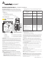
Layout and Dimensions
Battery Voltage
indicated for 12V
Battery
Battery Voltage
indicated for
24V Battery
> 14.8 (Preset) /
15.3V / 16.0V
> 29.6V (Preset) /
30.6V / 32.0V
> 13.3 But <(14.8V
(Preset) / 15.3V /
16.0V)
> 26.6V But < (29.6V
(Preset) / 30.6V /
32.0V)
Green
> 12.4
> 25.0V
Green+Yellow
> 11.6
> 23.2V
Yellow
> 11.2
> 22.2V
Yellow+Red
> 10.9
> 21.8V
Red
> 10.5
>21.4V
Status of LEDs
and Buzzer
*Walking LED’s - Fast + Beep (Indicates
charging in progress and the voltage is
higher than the programmed threshold
of Over Voltage Alarm)
*Walking LED’s - Slow (Indicates
charging in progress under normal
conditions)
Wire AWG #22 to 26
0.5A
Fuse
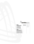
Fig 3. 0.25”/6.3 mm Female Quick
Connect Receptacle Terminal Lug
Threshold (14.8V (Preset) / 15.3V / 16V for 12V battery and 29.6V (Preset) / 30.6V /
32.0V for 24V battery). The loop is: (Red » Yellow » Green» All OFF)… repeats this
sequential loop.
65
56
(Green +Yellow + Red) - Blinking
3
B
65
4
A
14.9
36
2
56
Following pattern indicates voltage is
below the programmed threshold for
Low Voltage Alarm:
» (Red + Green) » (Yellow)… repeats
10 times
PCB
5
1
14.9
Fig 1. BW-01 Front View
Fig 1.:
1 – Red LED
2 – Yellow LED
3 – Green LED
4 – Buzzer (at the back)
5 – Programming Button
3.2
(Red + Green) » (Yellow + Beep)…
repeats 10 times
36
Fig 2. BW-01 Back View & Battery Connection (Note: Same dimensions as front view)
Fig 2.:
A – 1/4" (6.3mm) Quick Connect Tab Terminal
for connection to Positive (+) of the battery
B – 1/4" (6.3mm) Quick Connect Tab Terminal
for connection to Negative (-) of the battery
Installation: Please refer to Figs 1 and 2 above. The unit consists of a 65 x 65 mm
front plate with 4 x 3.2 mm holes for flush mounting on a wall / panel with 4 screws (#4,
Tapping, Flat Head). The Printed Circuit Board (PCB) and Battery Input Connectors (0.25”/
6.3 mm Quick Connect Tabs) are located at the back of the plate and project out to a
depth of 25.5 mm. For flush mounting on the wall / panel, a pocket / slot measuring 30
mm x 30 mm x 40 to 50 mm depth is required to be made to accommodate the projection
at the back.
Use AWG # 22 to 26 wires (e.g. telephone wires) to connect to the battery (See
Fig. 2). Use a 0.5A fuse in series with the Positive wire. The fuse should be as close as
possible to the battery Positive terminal (preferably within 7”).
Refer to Fig 2. Battery Positive (+) and Negative (-) connections to the unit are made
through Battery Input Connectors “A” and “B” (1/4”/6.3 mm Male Quick Connect Tabs).
For this connection, use 0.25”/6.3 mm Female Quick Connect Receptacle Terminal Lugs on
the wire ends (See Fig 3).
12V / 24V battery is detected automatically when voltage of 7 to 32V is seen on
connection of the battery. At startup, Red LED is activated as a sign of power up. After
some time, the unit is initialized and 12V / 24V battery is recognized. The State of Charge
is displayed thereafter.
LED and Buzzer Indications for Voltage Levels:
*NOTE: Term “Walking LEDs” has been used to indicate cyclical, sequential lighting
pattern of Red, Yellow and Green LEDs. This pattern indicates that charging is taking
place. Following 2 patterns are used:
• “Walking LED’s - Fast” + Beep: Indicates charging at voltage that is higher than the
programmed value of High Voltage Threshold (14.8V (Preset) / 15.3V / 16V for 12V
battery and 29.6V (Preset) / 30.6V / 32.0V for 24V battery). The loop is: {Red » Yellow
» (Green + Beep) » All OFF}… repeats this sequential loop.
• “Walking LED’s – Slow”: Indicates charging at voltage higher than 13.3V (12V
battery) / 26.6V (24V battery) but lower than the programmed value of High Voltage
-
> 21V
< 10.5 (Preset) or
< programmed
values of 10.6V
/ 10.7V / 10.8V
/ 10.9V / 11.0V
/11.1V / 11.2V
< 21V (Preset) or <
programmed values
of 21.2V / 21.5V
/ 21.6V / 21.8V
/ 22.0V / 22.2V /
22.4V
» All LEDs OFF. Unit enters
Sleep Mode. There is a beep every min.
High Voltage Alarm during Charging: Following voltage thresholds can be
programmed to warn about over voltage condition during charging (See programming
procedure given separately).
• 14.8V (Preset) / 15.3V / 16V for 12V battery
• 29.6V (Preset) / 30.6V / 32.0V for 24V battery
This facility can be used to indicate onset of “Equalization Stage” when charging Flooded
/ Wet Cell Batteries. During “Equalization Stage”, the battery is intentionally overcharged
to 15.3 to 16V (12V battery) / 30.6 to 32V (for 24V battery) for limited time of 1 to 3
Hrs. During this time, it is necessary to monitor the battery for overheating / electrolyte
level / measurement of individual cell voltages and for turning OFF Equalization at the
appropriate time.
The display pattern is “Walking LEDs – Fast” + Beep. In this pattern, the display / buzzer
loop is: {Red » Yellow » (Green + Beep) » All OFF}......Repeats this sequential loop.
NOTE: The unit will not reset even after the battery voltage drops below the programmed
Over Voltage Threshold. This is helpful to know that an over voltage condition existed. The
alarm can be reset manually as follows:
• Press and hold Programming Button » Beep will be heard » Release the Button Low Voltage Alarm: Following voltage thresholds can be programmed to warn
about low voltage condition (See programming procedure given separately).
• < 10.5 (Preset) or < programmed values of 10.6V / 10.7V / 10.8V / 10.9V / 11.0V
/11.1V / 11.2V
• < 21V (Preset) or < programmed values of 21.2V / 21.5V / 21.6V / 21.8V / 22.0V /
22.2V / 22.4V
When the programmed Low Voltage Threshold is reached, the following LED / Buzzer
pattern will be observed:
» (Red + Green) » (Orange + Beep)…….Repeats 10 times » (Red + Green) » (Orange)….. Repeats 10 times » All LEDs OFF. Unit enters Sleep Mode. There is a beep every minute so that it is clear that
the unit is not in a “3 Day Off Mode.”
NOTE: The unit will reset only when the battery voltage rises to > 13.3V (for 12 V battery)
/ 26.6 V (for 24V battery) i.e. when charging takes place.
3-Day Timer: A 3-Day Timer has been provided to automatically switch OFF the unit
after 3 days of switching ON of the Timer or if the battery voltage drops below 10.4V (for
12V battery) or 20.8V (for 24V battery). The Timer will be automatically switched OFF after
the battery voltage rises above 13,3V (for 12V battery) or 26.6V (for 24V battery).
ON / OFF Modes can be programmed as shown under heading “Programming
Alarm Thresholds / 3-Day Timer.”
SAMLEX AMERICA, INC.
| 1
BATTERY MONITOR BW-01 | OWNER'S MANUAL
Programming Procedure: Brightness of LED Display:
The unit comes
preset with brightness of the LEDs set at Normal (Bright). The brightness can be dimmed or
the LEDs can be switched OFF. Settings can be changed with the help of the Programming
Button (5, Fig 1). Settings are performed in sequential order in a loop: Bright » Dim » OFF
» Bright » Dim » OFF… repeats the loop.
For changing the Setting: Press and hold Programming Button » Beep will be heard
» Release the Button.
Please note that when the LED display is switched OFF, the Buzzer alarm protocols stay
active in the background. Hence, if Under Voltage / Over Voltage condition is activated,
the LED display and Buzzer alarm protocols for the abnormal condition will be activated.
Programming Procedure: Alarm Thresholds / 3-Day Timer
Thresholds of Low Voltage / High Voltage Alarms and Timer ON / OFF settings are
programmed with the help of Programming Button (5, Fig 1) and by monitoring the LED
and Buzzer indication patterns. CAUTION! Alarm thresholds are to be programmed
only when the voltage is between 10.5V and 13.3V (for 12V battery) and between
21V and 26.6V (for 24V battery). In this condition, the LEDs / Buzzer will not be
indicating (i) “charging” i.e., will not be displaying “Walking LEDs – Fast+Beep” or
“Walking LEDs – Slow” or (ii) "Low or High Voltage Alarm".
Programming Modes are SEQUENTIAL as shown in the sequence given below. This means
that in order to access programming of the desired parameter, it will be necessary to pass
through the previous programming positions. Press Programming Button (5, Fig 1) and
hold it in pressed condition. Release the Button ONLY when the LED + Beeping pattern for
the desired parameter is displayed.
Specifications
Battery System Voltage............................. 12V / 24V (Auto Detection)
Input voltage Range................................................7 VDC to 32 VDC
Input current............................................................ Less than 30 mA
Battery Input Connectors........¼” / 6.3 mm Male Quick Connect Tabs
Input Wiring..............................................................AWG # 22 to 26
Fuse* ..........................................................................................0.5A
Dimensions, mm.......................................................... 65 x 65 x 25.5
Weight..................................................................................... 35 gm
* In series with Positive wire preferably within 7” from the Battery Positive
2 YEAR LIMITED WARRANTY
Battery Monitor BW-01 manufactured by Samlex America, Inc. (the “Warrantor“) is
warranted to be free from defects in workmanship and materials under normal use and
service. The warranty period is 2 years for the United States and Canada, and is in effect
from the date of purchase by the user (the “Purchaser“).
The sequence starts with Programming Mode for Low Voltage Thresholds first followed by
High Voltage Thresholds and then followed by Timer ON/OFF. Before the start of each
Programming Mode, all the 3 LEDs and buzzer will blink simultaneously 3 times.
Warranty outside of the United States and Canada is limited to 6 months. For a warranty
claim, the Purchaser should contact the place of purchase to obtain a Return Authorization
Number.
To START, press Programming Button (5, Fig 1) and hold it in pressed condition. Release
the Button ONLY when the LED + Beeping pattern for the desired parameter is
displayed.
The defective part or unit should be returned at the Purchaser’s expense to the authorized
location. A written statement describing the nature of the defect, the date of purchase,
the place of purchase, and the Purchaser’s name, address and telephone number should
also be included.
» Long beep » {(Red+Yellow+Green+Beep) » (Red+Yellow+Green+Beep)}…
3 Times (Low Voltage Threshold Programming Menu starts)
LOW VOLTAGE MENU STARTS
12V Battery
24V battery
(Red + Beep) - 3 blinks 10.5V (Preset)
21V (Preset)
10.6
21.2
(Red + Yellow + Beep) - 3 Blinks 10.7V
21.5V
(Red + Yellow + Beep) - Steady 10.8V
21.6V
(Yellow + Beep) - 3 Blinks
10.9V
21.8V
(Yellow + Beep) - Steady
11.0V
22.0V
(Yellow + Green + Beep) - 3 Blinks 11.1V
22.2V
(Yellow + Green + Beep) - Steady
11.2V
22.4V
(Red + Beep) - Steady {(Red+Yellow+Green+Beep) » (Red+Yellow+Green+Beep)}… 3Times
(High Voltage Threshold Programming Menu starts)
HIGH VOLTAGE MENU STARTS
12V Battery
24V battery
Steady Red + Long Beep
14.8V
29.6V
Steady Yellow + Long Beep 15.3V
30.6V
Steady Green + Long Beep
16.0V
32.0V
If upon the Warrantor’s examination, the defect proves to be the result of defective
material or workmanship, the equipment will be repaired or replaced at the Warrantor’s
option without charge, and returned to the Purchaser at the Warrantor’s expense.
(Contiguous US and Canada only)
No refund of the purchase price will be granted to the Purchaser, unless the Warrantor is
unable to remedy the defect after having a reasonable number of opportunities to do so.
Warranty service shall be performed only by the Warrantor. Any attempt to remedy the
defect by anyone other than the Warrantor shall render this warranty void. There shall be
no warranty for defects or damages caused by faulty installation or hook-up, abuse or
misuse of the equipment including exposure to excessive heat, salt or fresh water spray, or
water immersion.
No other express warranty is hereby given and there are no warranties which extend
beyond those described herein. This warranty is expressly in lieu of any other expressed
or implied warranties, including any implied warranty of merchantability, fitness for the
ordinary purposes for which such goods are used, or fitness for a particular purpose, or
any other obligations on the part of the Warrantor or its employees and representatives.
There shall be no responsibility or liability whatsoever on the part of the
Warrantor or its employees and representatives for injury to any persons, or damage
to person or persons, or damage to property, or loss of income or profit, or any other
consequential or resulting damage which may be claimed to have been incurred
through the use or sale of the equipment, including any possible failure of malfunction
of the equipment, or part thereof. The Warrantor assumes no liability for incidental or
consequential damages of any kind.
Samlex America Inc. (the “Warrantor”)
www.samlexamerica.com
DETAILED PRODUCT INFORMATION
For a complete user manual including specifications, application notes, installation
instructions, trouble shooting and more, please visit the web page for this product on
www.samlexamerica.com. Product page can be found using the “Search by Model”
field.
Long Pause
(3-Day timer Programming Menu Starts)
3 DAY TIMER ACTIVATION
Short Beep (No LED)
3-Day Timer ON
Long Pause
3 DAY TIMER DE-ACTIVATION
Long Beep (No LED)
3-Day Timer OFF
Programming sequence ends. Release Programming Button
11004-BW-01-0914
SAMLEX AMERICA, INC.
| 2