1
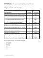
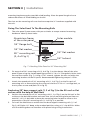
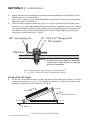
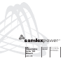
28"
Adjustable
Solar tilt
Mount
ADJ-28
Owner's
Manual
Please read this
manual BEFORE
installing your
solar tilt mount
oWneR'S MAnUAL | index
SECTION 1
Introduction .......................................................................... 3
SECTION 2
Components & Required Tools ............................................. 4
SECTION 3
Installation ...........................................................................5
SECTION 4
Warranty
.........................................................................10
DETAILED PRODUCT INFORMATION
For a complete user manual including specifications,
application notes, installation instructions, trouble
shooting and more, please visit the web page for this
product on www.samlexamerica.com. Product page can
be found using the “Search by Model” field.
2 | SAMLEX AMERICA INC.
Section 1 | Introduction
Mounting your solar panel inclined to an optimized angle with respect to the horizontal
axis can lead to increased annual collection of sunlight. Depending on the location and
time of the year, this could lead to up to 50% more solar energy collection compared to
horizontally mounted panels. Typically, for optimal annual performance, the solar panel
should be tilted at an angle equal to 0.9 times the latitude of the location with respect
to the horizontal. For optimal summer performance, the solar panel should be tilted to
an angle equal to latitude – 15 degrees and optimal winter performance the solar panel
should be tilted to angle equal to latitude + 15 degrees with respect to the horizontal.
The ADJ-28 Tilt Mount kit includes 4 Nos. sturdy 28” Aluminum mounting rails, 2 Nos.
14” Aluminum brackets (Fig. 1) and stainless steel hardware required to securely fasten
a solar panel to the roof of your Recreational Vehicle (RV) or any other flat surface. The
inclination of the solar panel can be adjusted to a desired angle with respect to the
horizontal axis.
...
....
....
...
7.4
...
...
....
.
1
1, 2
3, 4
5, 6
7.1 to 7.6
8.1 to 8.6
....
....
....
..........
..........
..
....
..........
........
7.6
....
..
....
....
.
.
.
..
....
....
.. ...
7.2
.
....
..........
..........
...
....
....
..
..........
8.5
...
....
.......... 8.2
..........
....
2
..
.......... 7.5
..........
....
....
..........
...
....
...
..........
...
....
4
....
....
..
....
....
8.3
...
....
7.3
5
3
....
8.4
8.6
8.1
7.1
28” Mounting Rail (for base support)
28” Mounting Rail (for supporting solar panel)
14” Aluminum Bracket for setting tilt angle
Carriage bolts
Wing nuts
Fig.1. ADJ-28 Tilt Mount
SAMLEX AMERICA INC. | 3
Section 2 | components & Required tools
List of Parts (included in the kit)
Part Description
Illustration
28” Aluminum mounting rail for base support
2
Fig. 1
28” Aluminum mounting rail for supporting
solar panel
2
Fig. 1
14” Aluminum bracket for setting tilt angle
2
Fig. 1
¼” - 20 x 1” stainless steel carriage bolts
6
Fig. 1
¼” - 20 stainless steel wing nuts
6
Fig. 1
Stainless steel serrated flange bolt ¼” - 20 x ¾"
4
Fig. 2
Stainless steel nylon insert locknut, ¼”
4
Fig. 2
Stainless steel flat washer, ¼” - 20
8
Fig. 2
Well nut-nut thread:
¼” - 20, length: 1”, shank diametre: ½”
4
Fig. 8
Stainless steel serrated flange bolt, ¼”- 20 x 1¼”
4
Fig. 8
Required Tools (not included in the kit)
•
•
•
•
•
•
Quantity
7/16” wrench
3/8” wrench
Hand Drill
½” drill bit
Pliers
Punch or Awl
4 | SAMLEX AMERICA INC.
Section 3 | installation
Pre-installation
With the incidence of sunlight on all photovoltaic modules, a voltage appears at the
output terminals of the photovoltaic module turning it into a live power source. To
avoid a shock hazard make sure the solar module is covered with an opaque (dark)
material such as paper / cloth.
Stainless Steel can be subject to a process called “thread galling” in which bolts can twist
off and/or the bolt threads seize to the nut’s thread. Apply anti-galling lubricant available at most hardware or auto-parts stores to all the stainless steel fasteners before installation. If anti-galling lubricant is not available, any standard lubricant will minimize
the occurrence of “thread galling”.
Well Nut For Anchoring 28" Base Support Mounting
Rails To The RV Roof Or Flat Surface
A Well-Nut is a bushing of tough neoprene rubber with a flange at the top end and a
captive brass nut mounted within the bore at the bottom end (Fig. 2). This is used to
anchor the 28" base support mounting rails (1, 2 of Fig.1) on to the roof of the RV or to
other flat surface. Typical installation is shown in Figs 3 to 6. Tightening a conventional
machine bolt or screw engages the captive nut thereby causing the bushing to expand
outwards. This fastens securely to thinner RV roofs by bulging up and against the bottom surface of the roof (Fig. 5). If used in a blind hole in a solid surface material, the
rubber will expand outwards to create a secure fastening (Fig. 6). The neoprene and
brass resist most environmental conditions. Additionally, the Well-Nut seals the drilled
hole effectively against air and liquid leakage.
flange
1/2” diameter
1/4” captive brass nut
Fig. 2. Construction of a Well Nut
SAMLEX AMERICA INC. | 5
Section 3 | installation
Typical Installation Of A Well-Nut
RV Roofing
Material
Well Nut
1/4”-20 x 11/4”
Serrated
Flange Bolt
Mounting
Rail
Captive
Brass Nut
Fig. 3. Well-Nut is inserted
into a pre-drilled hole with
its flange against the outer
surface. There is no need for
access to the
inner side.
Fig. 4. The 28" mounting
rail is placed against the
flange of the Well-Nut and
is secured by the 1/4"-20 x
11/4" serrated flange bolt
engaging the captive brass
nut.
Fig. 5. As the bolt is
tightened, the neoprene
body of the Well-Nut is
compressed and expanded,
forcing it tightly into the
bolt's threads and against
the inner surface of the
thin RV roof material.
Fig. 6. Installed in a blind
hole in a solid material,
the body of the Well-Nut
expands tightly against
the walls of the hole,
effecting a secure,
dependable fastening.
Installation Procedure
Determine the position of the solar panel on the RV roof or flat surface. While positioning panels, avoid shading of the solar panel by neighboring obstacles such as vents, airconditioners, TV antennas etc. As far as possible, position the panels to minimize wiring
distance between the solar panel and the charge controller. Place the panel at least 8-10
inches away from the RV roof edges and leave sufficient space to walk around the panel
and access the mounting hardware.
Make sure the thickness of the roof at the installation location is at least ½” thick and
the material is strong enough to provide mechanical support to the solar panel and
6 | SAMLEX AMERICA INC.
SECTION 3 | Installation
mounting hardware against possible wind loading. Place the panel length-wise to
reduce the effects of wind loading on the RV.
The slots on the mounting rails are sized to accept the ¼” hardware supplied with
the unit.
Fixing The Solar Panel To The Mounting Rails
1.
The solar panel frame comes with pre-cut holes to accept external mounting
hardware. Identify these holes.
Aluminium frame
of the solar panel
Solar module
1/4” flange bolt
1/4” flat washer
28 “ mounting rail
(3, 4 of Fig.1)
1/4” flat washer
1/4” locknut
Fig. 7. Attaching Solar Panel to 28” Mounting Rail
2.
Fix one pair of 28” mounting rails (3, 4 of Fig.1) to the shorter sides of the solar
panel frame using the slotted opening and the ¼”-20 x ¾" Flange Bolt, Nylon Locknut and flat washer (Fig. 7). Using a 7/16” wrench, tighten the nuts to secure the
mounting brackets to the PV panel. Recommended tightening torque is 15 lbs.
3.
Attach the second pair of 28” mounting rails (1, 2 of Fig.1) to the first pair of
mounting rails at one end using the wing nut and the ¼”-20 x 1" carriage bolt, so
that it pivots at one end (Point A in Fig. 9).
Anchoring 28" base support rails (1, 2 of Fig.1) to the RV roof or flat
surface with the help of Well-Nuts
4.
5.
Position the second pair of 28" mounting rails (1, 2 of Fig.1) on the RV roof or flat
surface at the desired location and mark two sets of mounting hole positions on
each 28” rail. It is desirable to have the mounting holes located as close to the
extremities of the 28” mounting rails (1, 2 of Fig.1) as possible.
To install the Well-Nuts to anchor the two base support mounting rails (1, 2 of
Fig.1), drill holes 1¼” deep at the marked positions using a ½” size drill bit. Make
sure that drilling does not interfere with pre-existing wiring installations.
SAMLEX AMERICA INC. | 7
Section 3 | installation
6.
7.
8.
Apply silicone or any appropriate sealant recommended by your RV dealer to the
drilled holes for water-proofing.
Insert the ¼” Well nut into the drilled holes so that only the flange section remains
above the roof surface (Fig. 3).
Fasten the base support mounting rails (1, 2 of Fig.1) to the roof surface by inserting the ¼ x1¼” serrated flange bolt into the Well-Nut. Tighten using a 3/8” wrench
to a recommended torque of 15 lbs. When the serrated flange bolt is screwed into
the Well-Nut, the material surrounding the well nut bulges slightly securing the
structure to the RV roof (Fig. 5, Fig. 8).
28” mounting rail
¼”- 20 x 1¼” flange bolt
¼” flat washer
Well-Nut
Rubber bushing material expands
when bolt is tightened to securely
anchor hardware
Fig. 8 Attaching 28” base support mounting rails
(1, 2 of Fig.1) to the RV roof or other flat surface
Setting The Tilt Angle
9.
Fix the 14” Aluminum brackets to the free ends of the mounting rail pairs as shown
in Figure 9 using the ¼”-20 x 1" carriage bolts and the ¼” wing nuts to obtain the
desired tilt angle (Point B and Point C in Fig. 9).
Point B
Solar Panel
14” Aluminum Bracket
Point A
Point C
RV Roof
Fig. 9 Tilt-up position (Side view)
8 | SAMLEX AMERICA INC.
SECTION 3 | Installation
10. Fig. 9 corresponds to one possible tilt-angle. Other tilt-angles maybe possible by
using different hole combinations.
Travelling mode
11. The mounting hardware should be connected in the tilted position only when the
RV is stationary. When the RV is in motion, the mounting hardware should be in
the flat mount position.
12. In order to do this remove the ¼”-20 x 1" carriage bolt carriage bolts by loosening
the ¼” wing nuts at points B and C (Fig. 9).
13. Lower the 28” mounting rails and the 14” brackets so that the square holes of
each set of the mounting rails and brackets align with each other and the solar
panel is flat (Fig. 10).
14. Using the ¼”- 20 x 1" carriage bolts and the ¼” wing nuts, secure the structure in
this position (Fig. 10).
Solar Panel
28” Mounting Rail
28” Mounting Rail
Point A
Point C
RV Roof
Point B
Fig. 10 Travelling Mode
SAMLEX AMERICA INC. | 9
Section 4 | Warranty
2 YEAR LIMITED WARRANTY
ADJ-28 Adjustable Solar Tilt Mount, manufactured by Samlex America, Inc. (the “Warrantor“) is warranted to be free from defects in workmanship and materials under
normal use and service. The warranty period is 2 years for the United States and Canada,
and is in effect from the date of purchase by the user (the “Purchaser“).
Warranty outside of the United States and Canada is limited to 6 months. For a warranty
claim, the Purchaser should contact the place of purchase to obtain a Return Authorization Number.
The defective part or unit should be returned at the Purchaser’s expense to the authorized location. A written statement describing the nature of the defect, the date of purchase, the place of purchase, and the Purchaser’s name, address and telephone number
should also be included.
If upon the Warrantor’s examination, the defect proves to be the result of defective
material or workmanship, the equipment will be repaired or replaced at the Warrantor’s option without charge, and returned to the Purchaser at the Warrantor’s expense.
(Contiguous US and Canada only)
No refund of the purchase price will be granted to the Purchaser, unless the Warrantor
is unable to remedy the defect after having a reasonable number of opportunities to do
so. Warranty service shall be performed only by the Warrantor. Any attempt to remedy
the defect by anyone other than the Warrantor shall render this warranty void. There
shall be no warranty for defects or damages caused by faulty installation or hook-up,
abuse or misuse of the equipment including exposure to excessive heat, salt or fresh
water spray, or water immersion.
No other express warranty is hereby given and there are no warranties which extend
beyond those described herein. This warranty is expressly in lieu of any other expressed
or implied warranties, including any implied warranty of merchantability, fitness for the
ordinary purposes for which such goods are used, or fitness for a particular purpose, or
any other obligations on the part of the Warrantor or its employees and representatives.
There shall be no responsibility or liability whatsoever on the part of the Warrantor or
its employees and representatives for injury to any persons, or damage to person or
persons, or damage to property, or loss of income or profit, or any other consequential
or resulting damage which may be claimed to have been incurred through the use or
sale of the equipment, including any possible failure of malfunction of the equipment,
or part thereof. The Warrantor assumes no liability for incidental or consequential damages of any kind.
Samlex America Inc. (the “Warrantor”)
www.samlexamerica.com
10 | SAMLEX AMERICA INC.
NOTES
SAMLEX AMERICA INC. | 11
contact
information
Toll Free Numbers
Ph: 800 561 5885
Fax: 888 814 5210
Local Numbers
Ph: 604 525 3836
Fax: 604 525 5221
Website
www.samlexamerica.com
USA Shipping Warehouse
Kent WA
Canadian Shipping Warehouse
Delta BC
Email purchase orders to
[email protected]
11013-ADJ-28-1212 MAN10007