1
®
MONITORING STATION
STAM-2/STAM-2 PRO
USER MANUAL
Program version 1.5.0
stam2_f_en 05/11
The dongle number,
required to register this software with the Manufacturer:
Minimum hardware requirements for the
monitoring station server:
• computer with installed Microsoft
Windows 2000 or Microsoft Windows XP
operating system
• Pentium II 400 MHz processor
• 128 MB RAM
• CD-ROM
• free PCI slot
• free serial COM port
• free USB port
• monitor with 1024 x 768 resolution
support
Minimum hardware requirements for the
monitoring station client:
• computer with installed Microsoft
Windows 98 SE, Microsoft Windows
Millennium Edition (ME), Microsoft
Windows 2000 or Microsoft Windows XP
operating system (Microsoft Windows
2000 or Microsoft Windows XP
recommended)
• Pentium II 400 MHz processor
• 128 MB RAM
• CD-ROM
• monitor with 1024 x 768 resolution
support
• sound card
SATEL's goal is to continually improve the quality of its products, which may lead to
alterations in their technical specifications and firmware. Current information on the
introduced modifications is available on our website.
Please visit us:
http://www.satel.pl
1.
2.
3.
4.
5.
6.
CONTENTS
MONITORING STATION FEATURES ............................................................................................ 3
CARD DESCRIPTION ................................................................................................................ 5
ADDRESSING CARDS............................................................................................................... 7
INSTALLING CARDS ................................................................................................................. 8
PROTECTION DONGLE ............................................................................................................. 8
STAM-2 PROGRAM INSTALLATION ........................................................................................... 9
6.1
6.2
6.3
6.4
INSTALLATION OF STAM-2 SERVER PROGRAM ............................................................................ 9
INSTALLATION OF STAM-2 CLIENT PROGRAM ........................................................................... 10
UPDATING STAM-2 PROGRAM ................................................................................................. 12
MOVING STAM-2 PROGRAM..................................................................................................... 13
7. OPERATION AND PROGRAMMING OF STAM-2 MONITORING STATION ......................................... 13
7.1
FIRST TIME RUN OF CLIENT PROGRAM ....................................................................................... 13
7.1.1
7.1.2
7.2
CLIENT PROGRAM INSTALLED ON THE SAME COMPUTER AS SERVER PROGRAM ........................................14
CLIENT PROGRAM INSTALLED ON A COMPUTER DIFFERENT FROM THAT WHERE SERVER PROGRAM IS
INSTALLED ...........................................................................................................................................14
MAIN WINDOW OF STAM-2 CLIENT PROGRAM ........................................................................... 15
Telephone receiver card ...........................................................................................................................17
Ethernet receiver card ..............................................................................................................................18
7.3
SERVER CONFIGURATION ......................................................................................................... 19
7.3.1 “CARDS” TAB .......................................................................................................................................19
Automatically finding devices ...................................................................................................................21
Manually defining devices ........................................................................................................................21
Additional configuration of STAM-1 P, STAM-1 R and STAM-1 K cards .................................................22
Additional configuration of STAM-1 PE and STAM-1 RE cards ...............................................................22
“Ethernet settings” tab ..........................................................................................................................22
“Reporting” tab .....................................................................................................................................23
Additional configuration of GSM modules ................................................................................................24
7.3.2 “INFORMATION” TAB .............................................................................................................................25
Changing TCP/IP port ..............................................................................................................................25
7.3.3 “ACTIONS” TAB ....................................................................................................................................26
Server .......................................................................................................................................................26
Client .........................................................................................................................................................26
7.3.4 “OPTIONS” TAB ....................................................................................................................................27
7.3.5 “SETTINGS” TAB...................................................................................................................................28
7.4
USER ACCOUNTS ..................................................................................................................... 34
7.4.1
7.4.2
7.4.3
7.5
7.6
7.7
ADDING NEW USER ..............................................................................................................................36
EDITING USER .....................................................................................................................................36
DELETING USER...................................................................................................................................37
CHANGING PASSWORD ............................................................................................................. 37
MIMIC BOARDS ......................................................................................................................... 37
SUBSCRIBERS.......................................................................................................................... 39
7.7.1 “INFORMATION” TAB .............................................................................................................................40
7.7.2 “FIND” TAB ..........................................................................................................................................41
7.7.3 "REPORT" TAB .....................................................................................................................................42
7.7.4 SUBSCRIBER .......................................................................................................................................43
“General” tab.............................................................................................................................................43
“Plans” tab ................................................................................................................................................44
“Identifiers” tab ..........................................................................................................................................46
Adding identifiers ..................................................................................................................................47
Editing identifiers ..................................................................................................................................47
“Definitions” Tab for “Contact ID” type of identifiers .............................................................................47
“Definitions” Tab for “Normal” type of identifiers ..................................................................................49
“Definitions” Tab for “SIA” type of identifiers ........................................................................................50
“Partitions” tab ......................................................................................................................................50
“GSM” tab .............................................................................................................................................54
2
STAM-2
SATEL
“Test transmissions” tab ...................................................................................................................... 55
“Ethernet” tab....................................................................................................................................... 56
“Video verification” tab ......................................................................................................................... 58
“Guardx” tab [only STAM-2 PRO]........................................................................................................ 59
“Nonstandard codes ” tab .................................................................................................................... 60
7.8
EVENT HANDLING WINDOWS ..................................................................................................... 61
7.8.1
7.8.2
7.8.3
7.8.4
7.8.5
7.8.6
7.8.7
7.9
WINDOW HEADER ............................................................................................................................... 64
SUBSCRIBER'S DATA ........................................................................................................................... 64
TABS.................................................................................................................................................. 65
ACTIONS ............................................................................................................................................ 67
COMMENT .......................................................................................................................................... 67
BUTTONS ........................................................................................................................................... 67
VIDEO VERIFICATION ........................................................................................................................... 68
EVENT LOG ............................................................................................................................. 69
7.9.1 EVENT MENU ...................................................................................................................................... 71
7.9.2 EVENT DETAILS................................................................................................................................... 71
Event data ................................................................................................................................................ 71
Subscriber data ........................................................................................................................................ 72
Data on event handling method ............................................................................................................... 72
7.9.3 COMMENTS ........................................................................................................................................ 73
New event ................................................................................................................................................ 73
To event ................................................................................................................................................... 74
7.9.4 FILTER ............................................................................................................................................... 74
7.9.5 ARCHIVING EVENTS TO FILE ................................................................................................................. 76
7.9.6 FILTERS ............................................................................................................................................. 77
Filter manager .......................................................................................................................................... 77
7.9.7 SERVICE ............................................................................................................................................ 78
7.10 STATUS BOARD ....................................................................................................................... 79
7.10.1 FIND .................................................................................................................................................. 81
7.10.2 DETAILED INFORMATION ...................................................................................................................... 82
7.11 REPORTS AND DOCUMENTATION .............................................................................................. 83
7.11.1 “SUBSCRIBER” TAB ............................................................................................................................. 83
7.11.2 “USER” TAB ........................................................................................................................................ 86
7.11.3 “SYSTEM” TAB .................................................................................................................................... 87
7.12 NOTES .................................................................................................................................... 88
7.12.1 CREATING NEW NOTE .......................................................................................................................... 88
8. LICENSE AGREEMENT ........................................................................................................... 89
SATEL
STAM-2
3
The STAM-2 is an advanced solution offered to the companies engaged in the business of
monitoring signals derived from security alarm systems. It is available in two variants: basic –
STAM-2 BASIC, and extended – STAM-2 PRO. This manual covers both variants of the
program.
The STAM-2 monitoring station consists from cards installed in the computer, as well as
software which enables management of the signals received by modules. It is possible to
receive transmissions sent through telephone line, Ethernet (TCP/IP) or GSM (SMS
and CLIP) networks. The STAM-2 program works in WINDOWS environment. It is a clientserver type of application which enables incoming events to be handled by some operators
on a number of workstations.
Note: Some features in the STAM-2 PRO program are only available, when the ETHM-1
module is connected to the alarm control panel.
If the STAM-2 program version 1.5 or later is to handle events received by the GSM module:
− GSM-4 module must have firmware version 4.11 of 13.05.2009 or later,
− GSM LT-1 module must have firmware version 1.11 of 13.05.2009 or later,
− GSM LT-2 module must have firmware version 2.11 of 13.05.2009 or later,
− "Fax/modem" option must be enabled in the module,
− speed of data transmission through the RS-232 port must be set at 19 200 bps in the
module.
1. MONITORING STATION FEATURES
• easy-to-install cards
• optional expansion of the station by adding more cards
• receiving transmissions sent via telephone line, Ethernet (TCP/IP) network or GSM (SMS,
CLIP) network
• detecting telephone line defect (telephone receiver cards), no network cable or
communication with Ethernet module (Ethernet receiver cards)
• compatible with:
− GSM-4 and GSM LT-1 / 2 modules (manufactured by SATEL)
− VISONIC RC-4000, VIRGO and MESSER radio stations
− modem
• automatic recognition of one of the following transmission formats:
− Silent Knight, Ademco slow (10 BPS)
− Sescoa, Franklin, DCI, Vertex (20 BPS)
− Silent Knight fast
− Radionics 1400 Hz
− Radionics 2300 Hz
− Radionics with parity 1400 Hz
− Radionics with parity 2300 Hz
− Ademco Express
− Silent Knight, Ademco slow - extended
− Sescoa, Franklin, DCI, Vertex - extended
− Silent Knight fast - extended
− Radionics 1400 Hz - extended
4
•
•
•
•
•
•
•
•
•
•
•
•
•
•
•
•
•
•
•
•
•
•
STAM-2
SATEL
− Radionics 2300 Hz - extended
− Contact ID (CID)
− SIA (telephone cards version 3.00 and higher; Ethernet cards version 3.01 and higher)
user friendly STAM-2 software, working in WINDOWS environment
client-server type of application which enables incoming events to be handled by several
operators on a number of workstations
option of smart distribution of events between the workstations
option to display event handling window at all workstations simultaneously
capability to handle events repeatedly
encrypted client-server communication
monitoring station data stored in an encrypted database file
defining the program user authority levels
simplified work of the monitoring station program operator:
− selection of intervention requiring events
− list of program user required actions
− storing program user reactions in memory
− reminder of unhandled events
saving major operations of the system users into event log
reporting situations which require intervention:
− alarm
− trouble (including lack of test transmission or transmission at wrong time)
− check for site status correctness (armed, disarmed)
status overviews of supervised sites:
− alarm reporting systems
− trouble reporting systems – possible verification of troubles occurring in the system
− armed systems – in case of bigger sites: a list of armed partitions
− status of communication with the systems
cyclic saving of data copy
capability to create auxiliary database, in parallel with the backup copy
capability to use the STAM-VIEW interface
interaction with GuardX INTEGRA alarm system administrator and user program – version
1.08.001 of 15.02.2011 or newer [only STAM-2 PRO]
capability to connect the video alarm verification unit
remote control of the site status using the virtual keypad [only STAM-2 PRO]
capability of creating detailed site plans [only STAM-2 PRO]
capability to use a map for presentation of the site status [only STAM-2 PRO]
handling subscribers in simple mode (no control of communication with the subscriber) or
extended mode (with control of communication with the subscriber)
detailed subscribers' data:
− up to a dozen or so identifiers of different types
− any number of information drawings (JPG or PNG files)
− decode tables (each code meaning and event description)
SATEL
•
•
•
•
•
•
•
•
•
•
•
STAM-2
5
− priority differentiation – order of reporting events which require intervention when events
are incoming simultaneously from many subscribers
− patterns of action in case of events which require intervention in partition – up to 5 items
extended event filtering
management of event filters
defining the actions needed to handle events
option to add comments to the actions
extended event handling menu
capability of fast event handling
archiving events, also to an external file
system of notes:
− information exchange between users
− defined validity period
− automatic display option
printing documentation regarding subscribers, reports for subscribers, reports on program
users and station system in PDF format
capability of archiving reports
selection of language version for STAM-2 Server and STAM-2 Client program
2. CARD DESCRIPTION
The card is a complete receiver of data sent by the control panels which enables
a supervision center to be organized for monitoring the security system status. It can be
installed on board of any PC computer (PCI slot), deriving only +12V power supply and
RESET signal from the computer. It is capable of working without the computer, if power
supply of approx. +12...15V is provided. The RESET signal is only necessary for operation
with the use of computer.
SATEL offers the following cards:
STAM-1 P
– base telephone receiver card (available in STAM-2 BT bundle);
STAM-1 R
– expansion telephone receiver card;
STAM-1 K
– expansion telephone termination receiver card for connecting mimic
boards;
STAM-1 PE
– base Ethernet receiver card (available in STAM-2 BE bundle);
STAM-1 RE
– expansion Ethernet receiver card;
Each telephone receiver card means that it is possible to connect the telephone line, i.e.
assign 1 telephone number to the monitoring station. Also, connecting the GSM module to
the COM port of the computer denotes that 1 additional telephone number (SMS/CLIP) is
assigned to the station. Each Ethernet receiver card means that it is possible to assign 1 IP
address to the monitoring station.
The card selection depends on what method of data transmission is used. The cards can be
connected with each other, which enables the monitoring station to support different
transmission methods and increase the number of telephone lines / IP addresses. The
STAM-2 monitoring station may comprise up to 16 interconnected cards (base receiver card
+ 15 expansion receiver cards of various types). Also, when GSM modules are connected to
the computer COM ports, the total number of supported cards and GSM modules is 16.
The STAM-1 K card accepts the STAM-1 PTSA mimic boards which enable visualization of
the status of monitored sites by means of LED indicators. One mimic board makes it possible
6
STAM-2
SATEL
to visualize the status of 64 objects. Additional mimic boards must be used for a greater
number of objects. Altogether, 63 mimic boards can be used for 1 monitoring station, which
means 4032 visualized objects.
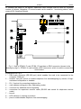
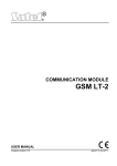
Fig. 1. View of STAM-1 P card. STAM-1 R card has no DB-9 connector (shown in the
drawing by digit 1). STAM-1 K card includes a DB-9 connector, which is used to connect the
mimic board.
Explanations for Fig. 1:
1 – DB-9 male connector (RS-232 port) which enables the card to be connected to the
computer COM port.
2 – headset mini-jack socket to enable telephone line eavesdropping by means of highresistance loudspeaker or headset.
3 – RJ-11 socket for connecting telephone line.
4 – card address setting pins (see: Addressing cards).
5 – connector for additional control signaling.
6 – connectors for expansion receiver cards (RS-232 and sound for telephone receiver
cards).
7 – buzzer.
8 – LED indicator. Lit during connection.
9 – pins to enable/disable telephone line eavesdropping.
SATEL
STAM-2
7
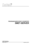
Fig. 2. View of STAM-1 PE card. STAM-1 RE card has no DB-9 connector to connect to the
computer COM port (indicated in the drawing by digit 1).
Explanations for Fig. 2:
1 – DB-9 male connector (RS-232 port) which enables the card to be connected to the
computer COM port.
2 – RJ-45 socket for connecting the Ethernet network. The socket incorporates two LEDs.
The green one indicates network connection and transmission, and the yellow one –
network transmission rate (OFF: 10Mb / ON: 100Mb).
3 – card address setting pins (see: Addressing cards).
4 – connector for additional control signaling.
5 – connectors for expansion receiver cards (RS-232 and sound for telephone receiver
cards).
6 – LED indicator.
7 – buzzer.
3. ADDRESSING CARDS
An individual address must be set for each installed card. The addresses may not be used
repeatedly. To set an address, use the pins (see Figures 1 and 2). The pin pairs are
designated JP1, JP2, JP3 and JP4. Addressing is carried out by means of jumpers placed on
the pins. The pins allow setting addresses from 0 to 15 (in hexadecimal mode: from 0 to F).
8
STAM-2
SATEL
In order to determine the address of a card, add up the values set on consecutive pin pairs,
according to Table 1.
Pin pair
Numerical value
(after setting the jumper)
JP1
JP2
JP3
JP4
1
2
4
8
Table 1.
4. INSTALLING CARDS
Prior to installation of a card in the computer, disconnect the computer from the
source of power supply.
The STAM-1 PE (Ethernet receiver base card) and STAM-1 RE (Ethernet receiver
expansion card) are dedicated devices designed for work in the local computer
networks (LAN). They cannot be connected directly to the public computer
networks (MAN, WAN). Connection to the public networks should be effected via
a router or xDSL modem.
In order to install the STAM-1 P or STAM-1 PE card in the computer:
1. Set the card address (see: Addressing cards).
2. Open the computer case.
3. Install the card in PCI slot.
4. Close the computer case.
5. Using the cable included in the bundle, connect the card DB-9 connector to the computer
serial COM port.
6. Connect the telephone line (STAM-1 P card) or network cable (STAM-1 PE card) to the
card socket.
In order to install the STAM-1 R, STAM-1 K or STAM-1 RE extension card in the computer:
1. Set the card address (see: Addressing cards).
2. Open the computer case.
3. Install the card in PCI slot.
4. Using the cable delivered with the expansion card, connect the card to the base receiver
card or another expansion card.
5. Close the computer case.
6. Connect the telephone line (STAM-1 R and STAM-1 K cards) or network cable
(STAM-1 RE card), or, optionally, the mimic board (STAM-1 K card) to the extension card.
If the card is to be installed outside the computer, proceed in the same way as described
above, skipping the steps which refer to installation of the card in computer PCI slot.
5. PROTECTION DONGLE
Installation of the STAM-2 server program is impossible without the protection dongle
(hardware key). Having installed the server program, leave the dongle in the USB port. If the
dongle is removed for more than 30 minutes, it will be unregistered and functionality of the
monitoring station will be limited. Such functions as editing subscribers and users accounts,
creating reports and configuring the server will be unavailable. 2 weeks after unregistering
the dongle, the monitoring station program will stop working.
SATEL
STAM-2
9
If your dongle gets damaged, please contact the SATEL Company. Replacement
is possible after you return the damaged dongle and pay a small handling
charge.
The SATEL Company shall not be held responsible for lost or stolen dongles. If
you loose your dongle, you must be prepared for high costs connected with
delivery of a new one.
6. STAM-2 PROGRAM INSTALLATION
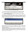
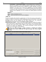
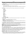
Insert the CD with installation program into the CD-ROM drive. The welcome screen should
appear in a while. Click on the command of chosen program installation and follow the
instructions.
If the splash screen fails to appear after the disk is inserted into the CD-ROM drive, the
autostart function of your CD-ROM must have been disabled. If this is the case, click twice on
the “My computer” icon and, after the resource window opens, on the CD-ROM icon. There is
the SetupStam2.exe file on the installation disk. Open it, e.g. by clicking on it twice, to bring
up the splash screen.
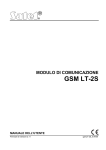
Fig. 3. Welcome screen of the installation package.
6.1 INSTALLATION OF STAM-2 SERVER PROGRAM
The server program should be installed on a computer to the serial COM port of which the
STAM-1 P or STAM-1 PE card is connected. If the server program finds no STAM-1 P or
STAM-1 PE card within a few minutes after being started, it will be terminated.
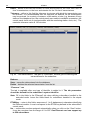
To begin installation, click on the “Install STAM-2 server program” command. During
installation, the protection dongle must be inserted into the computer USB port.
At installation stage, the users of STAM-1 monitoring station can import data from the
program. To do so, you must select the option “I have STAM-1 installed and want to import
data from it” (see Fig. 4), and then indicate the folder where the STAM-1 program is installed.
10
STAM-2
SATEL
Fig. 4. Importing STAM-1 program data.
Note: The database of STAM-1 monitoring station can only be imported during installation.
The STAM-2 monitoring station needs to be registered within 31 days of the server program
installation. After expiry of this period, the server program will stop working. The server
installer program offers optional registration at the end of installation procedure. Registration
is also possible at a later date on the website www.stam2.satel.pl or by using the form
included in the bundle. When filled in, the form should be sent by fax to the number (+48)
58 320 94 01. After registration, SATEL will send a license file to the e-mail address, or to the
mailing address (in case of regular postal mail). Installation of the license file will enable the
server program to be used without any time limitations.
6.2 INSTALLATION OF STAM-2 CLIENT PROGRAM
Installation of the client program is possible on the same computer on which the server
program has been installed. In addition, it may be installed on any number of workstations,
however the server program can support up to 3 or up to 10 clients, depending on the license
held.
SATEL
STAM-2
11
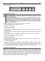
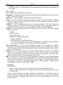
Fig.5. Example of configuration of the STAM-2 monitoring station.
To begin installation, click on the “Install STAM-2 client program” command. The Java Virtual
Machine is required for the client program to be operable, therefore it must be installed. The
"jre-6u25-windows-i586.exe" installation file can be found on the provided CD in the "java"
folder. Double click on the file to start the installation. You can also download the latest
version of the Java Virtual Machine from www.java.com/pl/download/.
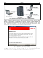
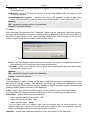
Fig. 6. Installation of Java Virtual Machine.
Installation of the Java Virtual Machine will begin after you click on the "Install" button
(see: Fig 6). A window will appear showing the installation progress (see Fig. 7).
12
STAM-2
SATEL
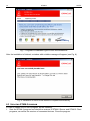
Fig. 7. Progress of installation type of Java Virtual Machine.
After the installation is finished, a window with suitable message will appear (see Fig. 8).
Fig. 8. Installation of Java Virtual Machine completed successfully.
6.3 UPDATING STAM-2 PROGRAM
In order to update the STAM-2 program, do the following:
1. Start the STAM-2 program and check the versions of STAM-2 Server and STAM 2 Client
programs, as well as the versions of connected devices. Close the program.
SATEL
STAM-2
13
2. Download the latest versions of the STAM-2 program and the updating program for
phone / Ethernet receiver cards and GSM modules from the www.satel.eu website, and
save them to disk.
3. In case of any trouble, prepare a backup copy to guarantee data recovery. Copy the
"Client" and "Server" folders (including their contents) to a safe place. The default access
path is C:\Program Files\Satel\STAM-2.
4. Disconnect the telephone lines (for STAM-1 P, STAM-1 R and STAM-1 K cards) and the
network cables (for STAM-1 PE and STAM-1 RE cards) from the card slots, so that the
monitoring station should not receive any events during the update process.
5. Update the firmware of telephone cards, Ethernet cards and GSM modules.
6. Reconnect the telephone lines and network cables to the appropriate card slots.
7. Start the installation of a new version of the program and follow the instructions. The new
version will replace the existing one.
8. Run the installed version of STAM-2 program.
6.4 MOVING STAM-2 PROGRAM
In the event of transfer of the STAM-2 program from one computer to another, follow these
steps:
1. Create the "Satel" folder on the new computer, C drive, "Program Files" folder, and then
create the "STAM-2" folder in it (C:\Program Files\Satel\STAM-2).
2. Copy the "Client" and "Server" folders, including its contents, from the old computer
(default access path: C:\Program Files\Satel\STAM-2) and paste them into the created
STAM-2 folder.
3. Manually create shortcuts to the STAM-2 program on the desktop and in the Start Menu,
or install the STAM-2 program, replacing the old version with the new one.
Note: When moving the data, be sure to create appropriate folders for the database backup
copy and the auxiliary database on the new computer.
7. OPERATION AND PROGRAMMING OF STAM-2 MONITORING STATION
The STAM-2 server program works as an ordinary application and starts after
logging into the system.
You can terminate the server program manually and then restart it. In order to terminate the
server program manually, you must:
1. Hover the cursor over the server icon displayed on the system taskbar.
2. Press the right mouse button – a menu will appear.
3. Highlight the “Exit” item and press the left mouse button.
4. A window will be displayed. Enter your login and password in the window and then press
the “OK” button.
Configuration of the STAM-2 server and operation of the monitoring station can be effected
by means of the STAM-2 Client program.
7.1 FIRST TIME RUN OF CLIENT PROGRAM
After starting the STAM-2 Client program, the login window will open (see Fig. 9).
As the program is case-sensitive, make sure when logging in, that the Caps
Lock has not been accidentally activated.
14
STAM-2
SATEL
Fig. 9. STAM-2 program login window.
7.1.1
CLIENT PROGRAM INSTALLED ON THE SAME COMPUTER AS SERVER PROGRAM
In order to log in, enter “satel” as the default password and click on the “Log in” button.
7.1.2
CLIENT PROGRAM INSTALLED ON A COMPUTER DIFFERENT FROM THAT WHERE
SERVER PROGRAM IS INSTALLED
Before you log in, it is necessary to define the server parameters (address and TCP/IP port of
the computer where the STAM-2 server program is installed). For this purpose, click your
mouse on the “Edit” button. The “Servers” window will open, displaying the list of defined
servers. You can define any number of servers for the client program to work with. By default,
the “Stam-2” server is defined (see Fig. 10).
Fig. 10. “Servers” window on first-time run of the program.
Default parameters of the “Stam-2” server allow the user to log in when the STAM-2 Client
program is run on the same computer as the STAM-2 Server program. You can edit the
server settings (see Fig. 11) after clicking on the “Edit” button, or add a new server after
clicking on the “Add” button.
Having defined the server parameters, you can return to the login window. If the name of
required server with which you want to communicate is not shown, click on the arrow at the
server name. A dropdown list will appear, from which you should select the server the client
program is to work with. If the name of required server is shown, enter the default password
“satel” and click on the “Log in” button.
SATEL
STAM-2
15
Fig. 11. “Server” window defining parameters of the server with which the client program is to
work.
7.2 MAIN WINDOW OF STAM-2 CLIENT PROGRAM
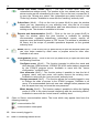
After login procedure, the main window of the program will open (see Fig. 12).
Fig. 12. Main window of STAM-2 Client program
Explanations for Fig. 12:
1
Click on the icon to open a window with information on the STAM-2
program and SATEL Company, manufacturer of the program.
2
Status board (Alt+T) – Click on the icon (or press Alt+T) to open a window
where the status of supervised sites can be checked (alarms, troubles, arm
statuses, test transmissions). The window is available to all users.
3
Event log (Alt+H) – Click on the icon (or press Alt+H) to open the event log
window. The window is available to users with the “viewing” authority level.
4
Handle alarms (Alt+1) – The icon is active when there are unhandled alarms.
The number at the icon shows how many alarms are still unhandled by the
user. Click on the icon (or press Alt+1) to open the "Alarm" tab (unhandled
alarms) in the "Event log" window. Available to users with the “handling”
authority level.
5
Handle troubles (Alt+2) – The icon is active when there are unhandled troubles.
The number at the icon shows how many troubles are still unhandled by the
user. Click on the icon (or press Alt+2) to open the "Troubles" tab (unhandled
troubles) in the "Event log" window. Available to users with the “handling”
authority level.
16
STAM-2
SATEL
6
Handle arm status events (Alt+3) – The icon is active when there are
unhandled arm status events. The number at the icon shows how many arm
status events are still unhandled by the user. Click on the icon (or press Alt+3)
to open the "Wrong arm status" tab (unhandled arm status events) in the
"Event log" window. Available to users with the “handling” authority level.
7
Subscribers (Alt+A) – Click on the icon (or press Alt+A) to open the window
where you can, depending on your authority level, view the list of current
subscribers, edit the current subscribers, add new subscribers or remove the
existing ones. The window is available to all users.
8
Reports and documentation (Alt+R) – Click on the icon (or press Alt+R) to
open the window where the print function is available for printing
documentation regarding subscribers, subscriber's reports, reports on
program users and station system in PDF format. The window is available to
all users, but the scope of possible operations depends on the granted
authority level.
9
Notes (Alt+N) – Click on the icon (or press Alt+N) to open the window where you
can view notes created by other users or prepare notes for other user.
Available to all users.
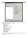
10
Configuration (Alt+K) – Click on the icon (or press Alt+K) to open the menu with
the following functions:
Configure server (Alt+K) – The function intended to define the cards and
other devices (GSM modules, VISONIC RC-4000 radio stations) supported
by the STAM-2 program server. Available to users with the “server
configuration ” authority level.
User accounts (Alt+E) – The function makes it possible to view the list of
program users, add new users, edit and/or remove the existing ones.
Available to users with the “user accounts” authority level.
Change password (Alt+P) – The function allows the currently logged in user
to change the code of access to the STAM-2 program. Available to all
users. It is recommended that each new user change his/her password so
that the supervisor may not know the user password.
Mimic boards (Alt+S) – The function makes it possible to define the lighting
mode of LEDs in the mimic boards interfacing with the monitoring station.
Available to users with the “mimic boards” authority level.
11
Client to Server communication status. The icons which may appear here have the
following meaning:
– communication OK
– communication interrupted
12
User currently logged in
13
Data of monitoring station server.
SATEL
STAM-2
17
14
Click on the icon (or press Alt+X) to open the menu with the following commands:
Help – opening the "Stam-2 Help" window.
Log out user (Alt+L) – after the current user has logged out, a next one can
log in.
Minimize (Alt+M) – minimizing the main window of the STAM-2 Client
program.
Close (Alt+X) – closing the STAM-2 Client program.
15
The icons illustrate the devices supported by the monitoring station: telephone / Ethernet
receiver cards, radio stations, modems and GSM modules supported by the STAM-2
program server. They can be designated with numbers from 0 to 15 and symbols Ex1,
Ex2 and Ex3 (the symbols are only used to designate radio stations, modems and GSM
modules). These characters correspond to the address of server supported card or
device. The icons have the following meaning:
- telephone card is working properly
- telephone card is receiving ring signal or is being configured
- telephone card has established connection with control panel
- telephone card is receiving data
- no telephone card, or trouble (to check the trouble details, refer to the “Event
log” window)
- GSM module is working properly
- GSM module is receiving data (SMS or CLIP type message)
- no GSM module, or trouble (to check the trouble details, refer to the “Event log”
window)
- Ethernet card is working properly
- Ethernet card is being configured
- no Ethernet card, or trouble (to check the trouble details, refer to the “Event log”
window)
– radio station is working properly
– no radio station or trouble (for details of the trouble, check the "Event log"
window)
Click on the icon of card / station / module to open a window with information on the
particular device, the port to which it is connected and its current status. In the event of
connected GSM module, the level of signal received by GSM antenna is also displayed.
A grayed out
icon means that no card / device has been defined for the given
address.
TELEPHONE RECEIVER CARD
A list of 10 recently received calls is displayed in the window. The list includes the date
and time of the call, consecutive number of call on that day and the phone number from
which the call was made. Additionally, the "Off-hook" or "On-hook" button is available,
depending on whether the receiver card is connected or disconnected. Click on the "Offhook" button to test the telephone line for correctness, and also to answer the call. Click
on the "On-hook" button to end the connection test or to terminate the connection.
18
STAM-2
SATEL
Fig. 13. Window of telephone receiver card with address 0.
ETHERNET RECEIVER CARD
The window will display information on the card – its IP, MAC address, data on the event
log and whether the card is configured or not. If the card is currently being configured, it
displays a progress indicator for settings, including configuration, subscribers and MAC,
as well as information about memory, additional card troubles or error during
configuration.
Fig. 14. Window of Ethernet card, address 12.
16
Current date and time.
SATEL
STAM-2
19
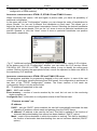
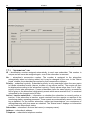
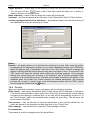
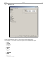
7.3 SERVER CONFIGURATION
The first operation to be carried out after starting the monitoring station program for the first
time and logging in, is configuration of the server. In order to configure the server, you must,
first of all, define the devices that are to be supported by the monitoring station program. The
“Cards” tab in the “Configuration” window is provided for this purpose.
Fig.15. Devices supported by the STAM-2 Server (example).
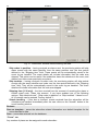
7.3.1
“CARDS” TAB
Address – the address set in the card or assigned by default to another device (GSM
module, VISONIC RC-4000, VIRGO, MESSER radio stations or modem). It is
recommended that you only check boxes next to the addresses which are set in the
connected cards, or to which other devices are to be assigned.
Port – the serial COM port of the computer to which the device supported by the monitoring
station program is connected. Editing is possible when the adjacent “Address” box is
checked.
Device – the type of device connected to the computer COM port (STAM-1 card, GSM
module, VISONIC RC-4000, VIRGO or MESSER radio stations, modem). Editing is
possible when the adjacent “Address” box is checked.
Buzzer – if this option is enabled and an event is received by the card, the card buzzer will
generate an additional audible signal, irrespective of the sounds generated by the
computer. The option only refers to the STAM-1 cards. Available after adding cards
(automatically or manually).
Attempts – enter in this field the number of failed monitoring attempts which, if occur within
the time period defined in the “Time” field, will result in registering the “Failed monitoring
attempt” event. If the last monitoring attempt was made by means of the DTMF system
and the control panel identifier has been sent, it will be shown at the event. If the preset
number of failed monitoring attempts does not occur within the defined period of time, the
time counter will be reset, and after another unsuccessful attempt, the time will be counted
20
STAM-2
SATEL
anew. Values from 0 to 255 minutes can be entered in the “Time” field. Entering 0 will
disable control of the unsuccessful attempts to connect to the monitoring station. The
option refers to the STAM-1 P, STAM-1 R and STAM-1 K cards. Editing is possible after
cards have been added (automatically or manually).
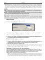
Fig. 16. “Cards” tab in “Configuration” window, before defining devices.
Time – enter in this field the maximum time interval counted from the unsuccessful attempt of
the control panel to establish connection with the monitoring station (a ring was received,
but no event was received). If more failed connection attempts occur during this time and
reach the number defined in the “Attempts” field, the “Failed monitoring attempt” event will
be registered. If the last monitoring attempt was made by means of the DTMF system and
the control panel identifier has been sent, it will be shown at the event. If the preset
number of failed monitoring attempts does not occur within the defined period of time, the
time counter will be reset. After another unsuccessful attempt, the time will be counted
anew. Values from 0 to 255 minutes can be entered in the “Time” field. Entering 0 will
disable control of the unsuccessful attempts to connect to the monitoring station. The
option refers to the STAM-1 P, STAM-1 R and STAM-1 K cards. Editing is possible after
cards have been added (automatically or manually).
Trouble – enter in this field the maximum time period in minutes, during which the card may
receive no events. After expiry of this time, the card trouble will be reported. Values from 0
to 65535 minutes can be entered in the “Trouble” field. Entering 0 will disable control of the
events receiving by the card. The option only refers to the STAM-1 cards. Editing is
possible after cards have been added (automatically or manually).
Filter – enter in this field the time of filtering the card events in seconds. If several identical
events are received within the defined time period (i.e. events with the same identifier and
code), only the first event will be added to the event log, the other ones being omitted.
Values from 0 to 2550 seconds can be entered in the “Filter” field. Entering 0 will disable
the event filtering. The option only refers to the STAM-1 cards. Editing is possible after
cards have been added (automatically or manually).
SATEL
STAM-2
21
Ring – indicate in this field the number of rings after which the telephone receiver card is to
establish connection with the control panel – Off hook. You can enter numbers from 1 to 9.
The option refers to the STAM-1 P, STAM-1 R and STAM-1 K cards. Editing is possible
after cards have been added (automatically or manually).
Information – information on the type of receiver card with the given address (TEL –
telephone, TCP/IP – ethernet) or another device assigned to that address (GSM – GSM
module, VISONIC, VIRGO, MESSER – radio stations, MODEM – modem). Additionally,
the firmware version of telephone / Ethernet receiver cards and GSM modules is shown.
The information is displayed when the devices supported by the monitoring station
program have been defined.
Configuration – the button available for STAM-1 P, STAM-1 R and STAM-1 K telephone
receiver cards (version 3.00 or higher), the STAM-1 PE and STAM-1 RE Ethernet cards
and the GSM modules. Press it to open a window of extra settings (see: Additional
configuration of STAM-1 P, STAM-1 R and STAM-1 K, Additional configuration of STAM1 PE and STAM-1 RE cards and Additional configuration of GSM modules).
Buttons:
Search – the button enabling automatic detection of cards connected to the computer serial
COM ports (see: Automatically finding devices).
Apply – the button making it possible to manually add devices supported by the monitoring
station program (see: MANUALLY DEFINING DEVICES). The button becomes active on
selecting the address for which the device is to be defined, or after deselecting the
address to which the device was previously assigned.
Close – button closing the window.
AUTOMATICALLY FINDING DEVICES
The program can by itself find the cards connected to the computer serial COM ports. To do
so, click on the “Search” button in the “Cards” tab of the “Configuration” window, and then
select one of the available ports which is to be searched.
The program cannot automatically find the GSM modules, VISONIC RC-4000,
VIRGO, MESSER radio stations and modems.
After the connected cards have been found, they must be appropriately configured.
MANUALLY DEFINING DEVICES
The program allows for manually adding all the supported devices. The GSM modules and
VISONIC RC-4000, VIRGO and MESSER radio stations as well as modems can only be
added manually.
To manually define a device, do as follows:
1. Open the “Configuration” window, and the “Cards” tab in it.
2. Determine address of the device, checking the appropriate “Address” box. Select any
unassigned address for the GSM modules, VISONIC RC-4000, VIRGO and MESSER
radio stations as well as modems, in which the address is not set.
3. Select the COM port to which the device is connected.
4. Select the type of device.
5. Click on the “Apply” button.
6. Define the “Buzzer”, “Trouble” and “Filter” options for all cards. For the telephone receiver
cards, determine the “Time”, “Attempts” and “Ring” parameters. In case of the STAM-1 P,
STAM-1 R and STAM-1 K (version 3.00 or higher), the STAM-1 PE and STAM-1 RE
cards and GSM modules, click on the “Config.” button to configure additional parameters
for these devices (see: Additional configuration of STAM-1 P, STAM-1 R and STAM-1 K,
22
STAM-2
Additional configuration of STAM-1 PE
configuration of GSM modules).
and STAM-1 RE
SATEL
CARDS
and
Additional
ADDITIONAL CONFIGURATION OF STAM-1 P, STAM-1 R AND STAM-1 K CARDS
When connecting the version 3.00 and higher of phone cards, you have the possibility of
additional configuration.
In the upper part of the "Configuration" window, you can change the order of handshakes for
phone formats. You can set a different first handshake on each card. This allows you to
adjust the device to the control panel transmission format. Selecting the desired handshake
will highlight the arrows beside. Click on the "up" arrow to move a particular handshake one
position upwards, or click the "down" arrow to move a particular handshake one position
downwards, respectively.
Fig. 17. Additional configuration window for telephone receiver cards, version 3.00 or higher.
At the bottom part of the "Configuration" window, you can select the CLIP service format:
FSK BELL 202, FSK V23 or DTMF. This option makes it easy to identify the calling party
number. Before choosing the appropriate format, consult the operator to make sure which is
the mandatory CLIP standard.
ADDITIONAL CONFIGURATION OF STAM-1 PE AND STAM-1 RE CARDS
The parameters available for programming depend on the card version. In case of the card
version 3.01 and higher (simple monitoring and SIA format), the configuration is performed in
two tabs of the "TCP/IP configuration" window. The lower versions of the cards are
configured by filling in only the active fields.
IP: – IP address programmed in the card.
MAC: – MAC card number.
Event memory – number of events received by the card, but not sent to the monitoring
station program yet.
Configured card – information on configuration status of the Ethernet card.
“ETHERNET SETTINGS” TAB
IP address
DHCP – with the “DHCP” option enabled, the card will automatically download the data
regarding IP address, subnet mask and gateway from the DHCP server.
IP address– IP address to be used by the card. This field is available if the function of
automatic data downloading from server has been disabled (“DHCP” option).
Mask – mask of the subnetwork in which the module is working. This field is available if
the function of automatic data downloading from server has been disabled (“DHCP”
option).
SATEL
STAM-2
23
Gateway – network gateway, i.e. IP address of the network device through which other
network devices communicate with the Internet or other local networks. This field is
available if the function of automatic data downloading from server has been disabled
(“DHCP” option).
Fig.18. “Ethernet settings” tab in “TCP/IP configuration” window before defining card
parameters.
DNS
DHCP – with the "DHCP" option enabled, the card will automatically download the DNS
server address data from the DHCP server.
IP address – DNS server address. The field is available if the function of automatic data
downloading from the server has been disabled ("DHCP" option).
“REPORTING” TAB
Fig. 19. “Reporting” tab in “TCP/IP configuration” window before defining card parameters.
Extended mode
Parameters defined in this area relate to handling subscribers in extended mode, i.e.
with the communications control.
Port – enter the number of the network port intended for communication in this field.
Values from 1 to 65535 can be entered. The value must be different from that
24
STAM-2
SATEL
entered for the other ports. The same port number must be entered in the reporting
settings of the subscriber device.
Station key – in this field, a string of 1 to 12 alphanumeric characters which determine
the key to be used for data encrypting during communication in the extended mode
should be entered. The identical station key must be entered in the reporting settings
of the subscriber device.
Simple mode
Parameters defined in this area relate to handling subscribers in the simple mode, i.e.
without the communication control. This feature requires connection of the Ethernet
cards, version 3.01 and higher.
Enabled – if this checkbox is checked, it will be possible to handle the subscribers in
the simple mode.
Port – this field is available if the "Enabled" box is checked. You must indicate the
number of the network port on which communication will take place. You can enter
values from 1 to 65535. The value must be different from that entered for the other
ports. The same port number must be entered in the reporting settings of the
subscriber device.
Station key – the field is available if the "Enabled" box is checked. You must enter
a sequence of 1 to 12 alphanumeric characters to define the key with which the data
will be coded during communication in the simple mode. The same station key must
be entered in the reporting settings of the subscriber device.
MAC control – when the option is enabled, the card will only receive transmissions from the
devices with defined MAC numbers. This enables the card to be protected from hacking
attempts. You can define the MAC numbers after the “MAC” button is pressed.
Buttons:
MAC – pressing the button will open a window where you can define MAC numbers for the
devices, from which the card is to receive transmissions. Up to 256 MAC numbers can be
defined. The button is active, if the “MAC control” option is enabled.
Apply – the button is active if any changes have been made in the window and enables
saving the introduced changes.
Close – closes the window.
ADDITIONAL CONFIGURATION OF GSM MODULES
Fig. 20. Additional configuration window for GSM module.
Password – a password for communication with the GSM module connected to the COM
port. In case of the GSM-4 module, the password must be identical with that programmed
in the module as “DWNL code”. In case of the GSM LT-1 module, enter 111111.
CLIP – a name, on the basis of which the CLIP type messages received from the given GSM
module will be identified (a corresponding event code can be assigned to this name at the
stage of adding / editing subscriber).
SATEL
STAM-2
25
[s] – time period defined in seconds, after which the GSM module will acknowledge receiving
the CLIP type message. You can enter values from 0 to 20. Value 00 means the function
is disabled.
Buttons:
OK – saves the changes made to the database.
Cancel – closes the window.
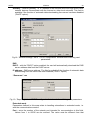
7.3.2
“INFORMATION” TAB
Fig. 21. “Information” tab in “Configuration” window.
The following information is provided in the tab:
• IP address of the computer with installed program of the server to which the client program
is connected
• Number of the TCP/IP port through which communication is effected
• Number of users logged in
• Information on the users logged in (first and last name, address, telephone, user status, IP
address of the computer from which they logged on)
• Duration of the connection to server
Buttons:
Change port – enables changing of the TCP/IP port number (see: Changing TCP/IP port).
OK – closes the window.
CHANGING TCP/IP PORT
In order to change the number of TCP/IP port through which the client-server communication
is effected, do as follows:
1. Open the “Information” tab in “Configuration” window.
2. Click on the “Change port” button.
3. A window will be displayed in which you should enter the new port number. It is possible
to enter values from 1 to 65535.
4. Click your mouse on the “Apply” button.
5. If the port is available, a window will be brought where you can accept or cancel the port
change. Before the next login, it will be necessary to change the server port settings in the
login window (see Fig. 11).
26
STAM-2
SATEL
Fig. 22. Window for changing port number.
7.3.3
“ACTIONS” TAB
Fig. 23. “Actions” tab in “Configuration” window.
The tab allows the user to define suggested actions that should be taken by the program
operator if specified events occur.
SERVER
In this section you can define actions for the selected system troubles. If this type of event is
generated, the texts entered will be displayed in red in the "Actions" section of the event
handling window for all computer stations.
CLIENT
You can define a list of actions that will be displayed in the window of each event that
requires handling. These actions are presented in black (the actions defined individually for
the subscriber are presented in red). The list of actions is local by nature, i.e. it only applies to
the computer workstation (the client program) on which it was created. If the same list of
actions is to be valid on another computer workstation, copy the "actions.txt" file to that
workstation (default access path: C:\Program Files\Satel\STAM-2\Client\src\lang\actions.txt).
SATEL
STAM-2
27
Button:
Apply – active after any changes are made to the window and allows to save the changes.
7.3.4
“OPTIONS” TAB
Fig. 24. “Options” tab in “Configuration” window.
Cancel all
“Should the need arise to delete all events requiring intervention (alarm, trouble, arm status
event), you should choose the button designated with the appropriate icon. Additionally, you
can specify a date by which all occurring events of the given type will be deleted. You can
define the date using the calendar which will be available when you check the "To date" box.
System time
You can set the time on the server. Enter the date and time in the "Time change on STAM-2
server" field and then confirm the change using the "Apply” button.
Move events to archive
Events can be stored in a dedicated part of the database. To do so, select a specific date in
the calendar in the "To date" field and confirm it by pressing the "Move" button. All the events
that took place by that time will be moved to the archive. They will be accessible when you
select the "Archive" option in the "Filter" window (see: Filter). The archived events will be
displayed in the "Event log" window tab. After the archiving is completed, detailed date and
time will appear to indicate the last time when the events were moved to the archive.
Close server
You can turn off the server from the computer station on which the server configuration was
run. To do so, click on the "Close" button.
28
7.3.5
STAM-2
SATEL
“SETTINGS” TAB
Fig. 25. Default settings in the "Settings" tab, "Configuration" window, STAM-2 PRO program.
SATEL
STAM-2
29
Event log
You can define the "Event log" appearance.
Font – the font size that will be used in the event list in the "Event log" window. The default
setting is 16.
Default event numbers – the number of events displayed in the "Event log" window. The
default setting is 200.
Default event filtering – the number of events meeting the defined criteria, which are
displayed in the "Filter" tab in the "Event log" window. The default setting is 500.
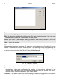
Status board
The area where you can define the look of the "Status board" window.
Visible map – if this checkbox id checked, a map is displayed as background in the "Status
board" window [only STAM-2 PRO].
Map – hover the cursor over the box and click on it with the left mouse button to open the
"Map" window, where you can add a map.
Fig. 26. “Map” window.
File name – add the access path to an image file with map in this field. The program
supports JPG and PNG file types.
Description – the field where the map name is to be entered.
Buttons:
– allows you to indicate the access path to the selected image file.
Save – saves the selected image file to the database. The button is active if the access
path to the image file has been indicated and a description of the map has been
entered.
Delete – deletes the map. The button is active if a map has been loaded.
Preview – allows you to preview a map selected from the list. The button is available if
a map has been loaded.
OK – saves the changes made to the database.
Cancel – closes the window.
30
STAM-2
SATEL
Objects size – the field allows you to specify the size of icons presenting individual
subscribers in the "Status board" window (the options are: small, medium and big). The
default size is "Big".
Empty objects visible – if this checkbox is selected, the icons presenting undefined
subscribers will be displayed in the "Status board" window. This does not apply when the
window displays a map. The option applies to all undefined subscribers whose
consecutive number is lower than that of the last-defined subscriber. The box is checked
by default.
Language
You can select the language version for the STAM-2 Server and STAM-2 Client program.
The programs may have the same or different language version. After selecting the
language, click on the "Apply" button, close the program (one or both of them, depending on
to which of them the changes have been made) and then restart it, because only then the
change of language version will take effect.
Server – in this field you can select the language version for the STAM-2 Server program.
Client – in this field you can select the language version for the STAM-2 Client program.
Other
Events for all – if this box is checked, the handling window will be displayed simultaneously
on all workstations when the monitoring station receives an event requiring intervention.
When one of the operators takes any action related to the event handling, the window will
be closed on the other stations. The box is checked by default.
Sounds with reader – if this box is checked, the events for which the WAV files are placed
in the "Sounds" folder will be signaled by a distinctive sound and reader comments in the
language chosen for the STAM-2 Client program. The box is checked by default.
Server
Arm status control – if this box is checked, the arm status events received by the
monitoring station will require handling. The box is checked by default.
Test transmission control – if this box is checked, the test transmission events received by
the monitoring station will require handling. The box is checked by default.
STAM-IRS service – if this box is checked, the power supply unit installed in the STAM-IRS
system is constantly monitored. Thus the information on troubles related to the device
power supply status will be sent to the monitoring station in the form of events.
SMS – if the GSM module is connected to the monitoring station, the monitoring station can
notify subscribers by SMS messages about receiving the alarm code. The SMS message
comprises a description of the event (up to 15 characters), the subscriber's name (up to 23
characters) and the subscriber's address (up to 24 characters). The message may contain
up to 62 characters. Move the cursor onto the "SMS" field and left click on it to open the
"SMS" window, where you can define the parameters of the above described message.
Fig. 27. “SMS” window.
SATEL
STAM-2
31
Sending devices address – select in this field the address of the connected GSM module
from which you want to send an SMS message notification of receiving the alarm code.
Transfer alarms – if this option is selected, the GSM module will be sending SMS
message notifications of receiving the alarm code.
Phone no – in this field, enter the number of GSM phone to which an SMS message is to
be delivered to inform that the alarm code is received.
Buttons:
OK – saves the changes made to the database.
Cancel – closes the window.
Default prefix GSM – the field where you should enter the country code. The country code
will be added before the cell phone number, to which an SMS message will be sent to
notify that the alarm code is received.
Viver settings – when you hover your cursor over the field and left-click on it, the "Viver
settings" window will open where you can define the parameters of this device.
Fig. 28. “Viver settings” window.
Ethernet – information provided in this area relates to:
IP address of the computer where the STAM-2 Server program is installed,
number of the TCP/IP port through which communication takes place.
Button:
Change port – enables changing the TCP/IP port number (see: Changing TCP/IP port).
32
STAM-2
SATEL
Transfer – information provided in this area relates to the conversion of events.
Port RS-232 – number of the port through which the events will be sent to another
monitoring station.
Output format – the field displays information about SurGuard format in which data will
be sent to another monitoring station.
Receiver No. [1-9] – enter in this field the number of receiver the data transfer from
which is simulated by the station. Values from 1 to 9 can be entered. By default: 1.
Line No. [1-99] – enter in this field the number of line the data transfer from which is
simulated by the station. Values from 1 to 99 can be entered. If the number is
between 1-9, then the SurGuard MLR2 format is chosen, if the number is between
10-99, then the SurGuard MLR2E format is chosen. By default: 1.
Test period [1-255] [s] – the parameter is used to control communication with the
monitoring station, for which the STAM-2 monitoring station acts as a converter. The
time is defined in seconds. Values from 0 to 255 can be entered. By default: 30 s.
Fig.29. Configuration of the server and VIVER module.
SATEL
STAM-2
33
Buttons:
OK – saves the changes made to the database.
Cancel – closes the window.
Backup
The area to define parameters for automatically making backup copy of the database. In
case of a primary disk trouble or loss of the database itself, the backup copy will be the
source to restore it. At the time of making the backup copy, a window is displayed to inform
you about it.
Active – check this box to activate creating a backup copy of the database.
Source folder – enter in this field the access path to the directory where you want the
STAM-2 database to be saved. By default: C:/Program Files/Satel/STAM-2.
Direct folder – enter in this field the access path to the directory where the database backup
copy is to be saved. It is recommended to create this directory on a different drive than the
one on which the STAM-2 database is placed. By default: D:/Backup STAM-2.
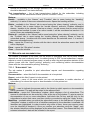
Scheduler – hover the cursor onto the field and left-click on it with your mouse to open the
"Scheduler" window where you can define a schedule for making the database backup
copy.
Fig. 30. “Scheduler” window.
Everyday – after you check this box and enter the time in the field next to it, the database
backup copy will be created automatically every day at the selected time. When you
check this box, the other fields in the window will become inactive.
Weekdays – when you select specific days and enter the time in the field on the right, the
database backup copy will be created automatically on selected days of the week at
a predetermined time.
Last backup – date and time of making the last database backup copy.
Next backup – date and time of making the next database backup copy.
Buttons:
OK – saves the changes made to the database.
Cancel – closes the window.
Additional database [only for STAM-VIEW users]
The area where you can define parameters for the auxiliary database. All operations and
events occurring in the monitoring station, receivers connected to it and sites monitored by it
34
STAM-2
SATEL
will be saved into the auxiliary database. The auxiliary database is parallel to the database
backup copy. In case of failure, it allows you to restore the database and recover the data
that have not been saved in the backup.
Active – check the box to activate creating the auxiliary database.
Path – enter in this field the access path to the directory where you want the auxiliary
database to be saved. It is recommended to create this directory on a different drive than
the one on which the database STAM-2 is placed.
Note: The files of database backup copy and auxiliary database should also be copied to
another data storage device. This can be done e.g. with the free Cobian Backup
program. This program allows you to create backups of data both locally and via the
network (e.g., FTP or shared folders). Thus, in the event of any failure of the operating
system or the computer itself, the backup copy will guarantee the recovery of data.
STAM-VIEW [only for STAM-VIEW users]
With this option enabled, it is possible to view the events coming from the site, using the web
browser: Mozilla Firefox, Google Chrome and Internet Explorer (version 8.0 or higher). The
program uses an external database, which is the continuously synchronized STAM-2
auxiliary base. The user (site owner, installer) logs, based on the name and password
(assigned by the company monitoring the site) and the characters from the image. If inactive,
the connection is closed after 10 minutes.
Enabled – if this box is checked, the connection between STAM-2 Server and STAM-VIEW
programs will be active.
The IP address of the database – enter in this field the IP address of the computer on which
the STAM-VIEW database will be located. The default setting is "Localhost".
Port – enter in this field the port number through which communication with the database will
be effected. The default setting is 3306.
Login – enter in this field the login name to be used by the STAM-2 Server to get access to
the STAM-VIEW database. The default setting is "admin".
Password – enter in this field the password to be used by the STAM-2 Server to get access
to the STAM-VIEW database. The default setting is "admin".
Button:
Apply – saves the changes made to the database.
7.4 USER ACCOUNTS
The window is available to users with the “user accounts” authority level.
When the monitoring station program is started with its factory settings (first time run), there
is one registered user with the name “satel”, and using the password “satel”, who has the
“Supervisor” status and nearly all available authorities. You cannot remove this user, or
change his status, or cancel his “user accounts” authority.
After the first run, the factory user password “satel” should be replaced with
another one.
User – User’s name. Filling this field is necessary. It is recommended that the user’s first and
last name (surname) be entered. The user’s name is to be entered when logging into the
server program. It is saved in the event log at all events handled by this user. It will be also
included in the created reports.
Address – User’s residence address. Filling this field is not necessary. It is recommended to
fill it, so that the user can be contacted, if needed. The user’s address is saved in the
event log at all events handled by this user.
SATEL
STAM-2
35
Fig.31. “User accounts” window at the first time run of the monitoring station program.
Telephone – Number of the user's home or mobile phone. Filling this field is not necessary. It
is recommended to fill it, so that the user can be contacted, if needed. The user’s
telephone number is saved in the event log at all events handled by this user.
Password – User’s password. Filling this field is necessary. The password is required to log
into the server program. It must have at least 4 characters. The program is case-sensitive.
After the first login, the user should change the password assigned to him by the person
who added him to the user list (see: Changing password).
Status – A status must be granted to each user. By default, a particular authority level is
assigned to each status. One of the 3 following statuses can be chosen: “Operator”,
“Installer” or “Supervisor”. The “Operator” is only granted the authorities of the “Event log”
category. The ”Installer” is given all the authorities included in the “Subscribers” category
and, additionally, is authorized to view event log, print reports and documentation. The
“Supervisor” is granted all the authorities, except for the simple handling of events. The
authorities possessed by the user with a particular status can be freely changed, which
practically means that the status is primarily a template, useful when creating and editing
users. During the use of the monitoring station program, the status will decide which of the
notes sent (see: Notes) will be received by the particular user.
Authorities – The authorities determine the scope of access to the monitoring station
program. They are subdivided into three main categories: event log, subscribers and other.
• Event log
− viewing – the user can only view the history of events (he cannot handle the events,
unless he has been granted the “handling” authority level).
36
STAM-2
SATEL
− handling – the user can only handle events (he cannot view the events log, unless he
has been granted the “viewing” authority level, but he can handle the older events by
means of the “Status board” window).
− simple handling – the user with the “handling” authority level can handle events in an
easy way, i.e. the event will be considered as already handled immediately after the
user clicks on the “Handle” button.
− clearing troubles – the user can clear unhandled troubles in the “Status board”
window, by clicking twice on the subscriber and opening the detailed information
window (when cleared, the troubles will be considered as already handled and inactive).
− clearing alarms – the user can clear unhandled alarms in the “Status board” window,
by clicking twice on the subscriber and opening the detailed information window (when
cleared, the alarms will be considered as already handled).
• Subscribers
− adding – the user can add new subscribers and restore deleted ones. Unless he has
been granted the “editing” authority, the user will not be able to edit the settings of
added subscriber after closing the “Subscriber” window.
− editing – the user can edit the existing subscribers.
− editing skips – the user with “adding” or “editing” authorities can define the rules for
skipping the incoming events.
− editing time areas – the user with “adding” or “editing” authorities can define the “Time
areas” for the subscriber.
− deleting – the user can delete subscribers.
• Other
− printing documentation – the user can print documentation regarding the monitoring
station in PDF format.
− printing reports – the user can print subscriber reports, reports on activity of selected
program users, as well as event log and system performance statistics in PDF format.
− server configuration – the user can configure the server.
− user accounts – the user can add, edit and remove other users.
− mimic boards – the user can define the lighting mode of mimic board LEDs.
7.4.1
ADDING NEW USER
In order to add a new user, do the following:
1. Open the “User accounts” window. An empty item in the list, intended for adding new
users, will be highlighted as the active field.
2. Enter the user name.
3. Enter additional information on the user (address, telephone), so that he can be
contacted, if necessary.
4. Enter the user password.
5. Select the user status.
6. Click on the “Save” button.
7.4.2
EDITING USER
In order to change the user settings, do as follows:
1. Open the “User accounts” window. An empty item in the list, intended for adding new
users, will be highlighted as the active field.
2. Click on the user whose data you want to edit.
SATEL
STAM-2
37
3. Make changes to the user settings.
4. Click on the “Save” button.
Note: If the user whose data have been edited is logged in, any changes regarding his
name, password or authorities will take effect after logging out of the user.
7.4.3
DELETING USER
In order to delete the user, do as follows:
1. Open the “User accounts” window. An empty item in the list, intended for adding new
users, will be highlighted as the active field.
2. Click on the user you want to delete.
3. Click on the “Delete” button.
4. In the window that will appear, confirm the intention to delete the user by clicking on the
“Yes” button.
Note: If the user being deleted is logged in, he will be able to operate the monitoring station
program until he logs out.
7.5 CHANGING PASSWORD
The function is available to all users. It is recommended that each user, after the first login,
change the password assigned to him by the person who added him to the user list. In order
to change the password, do as follows:
1. Open the “Change password” window.
Fig. 32. Password change window.
2.
3.
4.
5.
Enter the previous password in the “Old password” field.
Enter the new password in the “New password” field.
Re-enter the new password in the “Confirm password”.
Click on the “Apply” button.
7.6 MIMIC BOARDS
The window enables configuration of the mimic boards connected to the monitoring station.
Number of boards (0-63) – enter in this field the number of mimic boards connected to the
monitoring station. Up to 63 mimic boards can be connected (each board illustrates the
status of 64 subscribers). Entering 0 will disable support of the mimic boards. Do not enter
the greater number of boards than in reality. When you enter a smaller number of boards
than in reality, only the indicated number of boards will be supported. Factory default: 0.
38
STAM-2
SATEL
Fig. 33. “Mimic boards” on first-time run of the program.
Frequency x0.5s (1-255) – define in this field with what speed the LED lighting templates are
to move. The entered value is multiplied by 0.5 seconds. You can enter values from 1 to
255 seconds. Factory default: 4.
Indicate received event – check this box if the mimic boards are to signal receiving events
from the subscriber. Receiving an event will be signaled by the alternate blinking of the
subscriber assigned LEDs for 2 seconds. After elapse of this time, the LEDs will indicate
the subscriber's status again.
1 – check this box to see how the template will be displayed on one LED. The LED is
represented in graphical form.
2 – check this box to see how the template(s) will be displayed on two LEDs. The LEDs are
represented in graphical form.
Template for LED 1 – LED 1 lighting template for the following statuses:
− Armed
− Partially armed
− Disarmed
− Armed - wrong status
− Partially armed - wrong status
− Disarmed - wrong status
Template for LED 2 – LED 2 lighting template for the following statuses:
− Alarm
SATEL
STAM-2
39
− Trouble
− Alarm, Trouble
Template for LEDs 1 and 2 – LEDs lighting template for the following statuses:
− Subscriber not in database
− Subscriber inactive
Click on the selected template to display it on the LED/LEDs in the upper right-hand corner of
the window.
Each template is represented in graphical form on 8 fields. The LED is ON, when the field is
selected. To select / deselect the required field, click on it with our mouse pointer.
Buttons:
Apply – saves introduced changes to the database and restarts mimic board LEDs.
Close – closes the window.
7.7 SUBSCRIBERS
The window is available to the users who possess the “Subscribers” category authorities
(“adding”, “editing” or “deleting”).
The window displays a subscriber list. Depending on the granted authority level, the user can
add, edit or delete the subscribers. When editing subscribers, the program remembers the
last item from the list as well as the size and width of the displayed window.
No. – subscriber's consecutive number. The number is assigned to the subscriber
automatically when he is being added, but it may be changed by the user. In the “Status
board” window, the subscribers are sorted by their consecutive numbers.
Name – subscriber's first and last name.
Buttons:
New – active if the user has the “adding” authority. Allows adding new subscribers. If
a subscriber data template has been created, you can press the button to create a new
subscriber, for which the data from the template will be entered by default (see: description
of the "Save as template" button).
Delete – active if the user has the “deleting” authority. Allows deleting subscribers.
Edit – active if the user has the “editing” authority and after the first subscriber is added.
Allows editing the existing subscribers' data and settings.
Restore – displayed after deleted subscribers are found (see: “Find” tab), if the user has the
“adding” authority. Allows restoring the deleted subscriber (his setting will not be restored).
Filter – opens the "Event log" window with a tab which will display events related to the given
subscriber selected in the upper portion of the "Subscribers" window.
Details – opens the "Detailed information" window (see: Detailed information)
with information related to the given subscriber.
Plans – opens the "Site plans" window. The window displays a list of plans defined for the
specific subscriber. Click on the required plan and press the "Preview" button to familiarize
with the plan of monitored site.
Export – used to export subscribers. Highlight the selected subscribers in the list (holding
down the Ctrl key and left clicking your mouse) and click on the button. The "Save" window
will open, where you can select the location and file name to which the subscribers will be
exported.
Import – opens the "Open" window, where you can select the location and file name from
which the subscribers will be imported. Only the subscribers with currently non-existent
identifiers will be imported.
Cancel – closes the subscribers list window.
40
STAM-2
SATEL
Fig. 34. “Subscribers” window with “Information” tab on first-time run of the program.
7.7.1
“INFORMATION” TAB
ID – identification number assigned automatically to each new subscriber. This number is
unique and will never be assigned again, even if the subscriber is removed.
No. – subscriber's consecutive number. The number is assigned to the subscriber
automatically when he is being added, but it may be changed by the user. In the “Status
board” window, the subscribers are sorted by their consecutive numbers.
Priority – subscriber's priority. Subscriber's priority is only meaningful when the user wants
to handle unhandled events (alarms, troubles or arm status events). The events will then
be displayed according to the subscriber's priority. Priority values range from 0 to 9. Highpriority events take precedence. If some subscribers have the same priority, precedence
will be given to the subscriber's high-priority events which were received first, i.e. remained
unhandled for the longest period of time.
Active / Inactive subscriber – information on whether the subscriber is currently active or
inactive. If the subscriber is inactive, events received from him require no reaction of the
monitoring station operating personnel. These events are automatically saved in the event
log as handled. For the inactive subscriber, neither test transmissions, nor consistence of
arming/disarming with time areas are checked. The “Status board” displays no information
on the inactive subscriber's status.
Subscriber – subscriber's first and last name (or company name).
Address – subscriber's address.
Telephone – subscriber's telephone number.
SATEL
STAM-2
41
Installer – data of the company or person who installed the alarm security system at the
subscriber's premises, or is currently responsible for maintenance and operability of the
system.
Displayed below the “Installer” field is additional information on the subscriber (see: “General”
tab). The adjacent field shows a list of identifiers defined for the subscriber (see: “Identifiers”
tab).
7.7.2
“FIND” TAB
Fig. 35. “Find” tab (part of “Subscribers” window) on the first-time run of the program.
The “Find” tab makes it possible to find any subscriber (also a deleted one).
Text – the field where the character string you are searching for should be entered. The field
can be left empty: if this is the case, the search will only be based on the other search
criteria defined.
Where – the place where to search for the character string entered into the “Text” field. You
can select the following places:
− in names
− in addresses
− in installers
− in information
− anywhere
− in telephone numbers (the program will search all telephone and GSM related fields).
Active – check this box if the subscriber you search for is active. By default, this checkbox is
checked.
Inactive – check this box if the subscriber you search for is inactive.
Note: If the “Active” and “Inactive” boxes are checked at the same time, the search will
include both categories of subscribers, similarly as when none of the boxes is
checked.
42
STAM-2
SATEL
With identifiers – check this box if an identifier has been assigned to the subscriber
searched for. By default, this checkbox is checked. See also “Identifiers”.
Without identifiers – check this box if no identifier has been assigned to the subscriber
searched for.
Note: If the “With identifiers” and “Without identifiers” boxes are checked at the same time,
the search will include both categories of subscribers, similarly as when none of the
boxes is checked.
Identifiers – this field is available when the “With identifiers” box has been checked. It
enables a subscriber to be found on the basis of identifier(s). If the “With identifiers” box is
checked and the “Identifiers” remains blank, the search will include all subscribers who
possess identifiers.
Deleted – check this checkbox if the subscriber you are searching has been deleted.
Checking the box will block access to the boxes: “Active”, “Inactive”, “With identifiers” and
“Without identifiers”.
Buttons:
Search – starts searching the database. The list of subscribers who meet the defined criteria
will be displayed in place of the list of all subscribers.
Clear – restores default settings of the “Search” tab and brings up the list of all users.
7.7.3
"REPORT" TAB
The "Report" tab provides information about subscribers: consecutive number, name,
address, identifiers, and GSM phone numbers. The data can be sorted by column name, as
may be required. Additionally, you can move the whole columns, changing their position in
relation to each other. To do so, click on the column name and holding down the left mouse
button drag the column to the desired location.
Button:
Update – updates the report with the changes recently made to all subscribers' data.
Fig. 36. A report example in "Report" tab (part of "Subscribers" window).
SATEL
7.7.4
STAM-2
43
SUBSCRIBER
The window allows you to enter the subscriber's data. It will open on pressing the “New” or
“Edit” buttons in the “Subscribers” window.
Before entering the data, only the “General” tab is available. The “Plans” and “Identifiers” tabs
will only be available after the data are entered into the “Subscriber”, “Address” and
“Telephone” fields and then saved, which amounts to adding the subscriber to database. The
skipping settings (on right-hand side of the window) are only available when the user has the
“editing skips” authority.
“GENERAL” TAB
ID – identification number assigned automatically to each new subscriber. The number is
unique and will never be assigned again, even after the subscriber is removed.
No. – subscriber's consecutive number. The number is assigned to the subscriber
automatically when he is being added, but it may be changed by the user. To do so,
double-click on the "No." field. When the field text is highlighted, you can change the
assigned number. In the “Status board” window, the subscribers are sorted by their
consecutive numbers.
Priority – subscriber's priority. Subscriber's priority is only meaningful when the user wants
to handle unhandled events (alarms, troubles or arm status events). The events will then
be displayed according to the subscriber's priority. Priority values range from 0 to 9. Highpriority events take precedence. If some subscribers have the same priority, precedence
will be given to the subscriber's high-priority events which were received first, i.e. remained
unhandled for the longest period of time. By default, the subscriber's priority is set to 1.
Active – the box must be checked if the subscriber is to be active. By default, the box is
checked. If the subscriber is inactive, events received from him require no reaction of the
monitoring station operating personnel. These events are automatically saved in the event
log as handled. For the inactive subscriber, neither test transmissions, nor consistence of
arming/disarming with time areas are checked. The “Status board” displays no information
on the inactive subscriber's status.
Subscriber – enter the subscriber's first and last name or company name in this field. The
field must be filled in.
Address – enter subscriber's address here. The field must be filled in.
Telephone – enter the subscriber's telephone number in this field. The field must be filled in.
Installer – enter in this field the data of the company or person who installed the alarm
security system at the subscriber's premises, or is currently responsible for maintenance
and operability of the system.
Additional information – here you can enter additional information on the subscriber, for
example, the telephone numbers to which the GSM module will be able to send an SMS
message notifying you of the event (see: Tabs in the event handling window section). It is
recommended that the data be entered in the following way: first the name of the phone
owner, and then the phone number (e.g. John Smith 585656565).
Skipping – options available to users with “editing skips” authority. They allow you to define
how to handle the alarm / trouble event codes coming from the subscriber.
Skip nothing – no alarm event will be omitted. Each of them will bring up the alarm
window.
Skip identical code – having received an alarm event, the monitoring station will skip
alarm events with the same identifier and code over the time period defined in the
“Skipping time” field. These events will be automatically saved in the event log as
handled. The event details will include information that the code was skipped.
44
STAM-2
SATEL
Fig. 37. “Subscriber” window before entering the data.
Skip codes in partition – having received an alarm event, the monitoring station will skip
alarm events with the same identifier from the same partition over the time period
defined in the “Skipping time” field. These events will be automatically saved in the
event log as handled. The event details will include information that the code was
skipped. This option can be useful if the subscriber has a few detectors in the room, and
alarms from them mean practically one alarm.
Skip troubles – having received a trouble code, the monitoring station will skip trouble
events with the same identifier and code over the time period defined in the “Skipping
time” field. They will be automatically saved in the event log as handled. The event
details will include information that the code was skipped.
Skipping time [1-30 min] – the time counted from the moment of receiving the alarm or
trouble event code. Taken into account, if you have enabled one of the following
options: “Skip identical code”, “Skip codes in partition” or “Skip troubles”. Values fro m 1
to 30 minutes can be entered. Factory default: 1.
Simple handling – if this box is checked, events received from the subscriber will be
considered as handled immediately after the user clicks on the “Handle” button in the
event handling window.
Buttons:
Save as template – saves the subscriber related information as a default template for the
new subscriber's data.
Save – saves data entered into the database.
“PLANS” TAB
Any number of plans can be assigned to each subscriber.
SATEL
STAM-2
45
Fig. 38. “Plans” tab in “Subscriber” window, before adding a plan.
File Name – enter in this field the access path to the graphic file with the plan. You can
indicate the access path by clicking on the
button. The program supports the following
file types: JPG and PNG.
Description – the field where you should enter description of the plan.
Buttons:
– enables the access path to the graphic file to be indicated.
Save – saves the selected graphic file into the database, provided that description will be
added. The button is active, if the access path to the graphic file has been indicated.
Delete – deletes the selected plan. Click your mouse in the list (column on the left-hand side
of the window with plan descriptions) on the plan to be deleted, and then on the “Delete”
button.
Zones – displays a list of zones in the site assigned to an identifier in Contact ID format. The
list includes identifier, partition number as well as the zone number and description. The
button is available after a plan has been loaded [only STAM-2 PRO].
Preview – allows preview of the plan selected from the list. The button is available after
several plans have been loaded.
In the STAM-2 PRO program, you can place zones (detectors) on the plan. In order to
arrange the detectors, follow these steps:
1. Select the given plan from the column on the left-hand side of the window.
2. Click on the "Zones" button. A list of zones assigned to the given subscriber will be
displayed.
46
STAM-2
SATEL
3. Double click on each zone name in the list. In the upper left corner of the plan,
a pictogram appears in the shape of a small gray circle which symbolizes the given zone.
4. Put it on the plan in the place where the detector is.
5. Arrange the other detectors in a similar way.
You can check where the given detector has been placed. After selecting one of the zones in
the open list, the relevant pictogram on the plan will be highlighted in green. The plan also
serves informational purposes. When the monitoring station receives the alarm code from
a given zone, the corresponding pictogram will be highlighted in red.
“IDENTIFIERS” TAB
The tab contains a list of identifiers defined for the subscriber. It allows for adding new
identifiers, as well as editing and deleting the existing ones.
Type – the subscriber-assigned identifier can be of the following type:
Normal – identifier for transmission in formats other than Contact ID and SIA.
Contact ID – identifier for transmission in the Contact ID format.
SIA – identifier for transmission in the SIA format.
Reservation – identifier is only reserved for the subscriber. Defining any codes or settings
for it is impossible.
Identifier – each subscriber can be assigned any number of identifiers. The identifier has
hexadecimal format (digits and letters from A to F). It cannot, however, include the digit 0
inside. See also: Adding identifiers and Editing identifiers.
A change of the identifier type is saved automatically.
A change of the identifier type will delete all the identifier settings.
Fig. 39. “Identifiers” tab before adding identifiers.
SATEL
STAM-2
47
Extended kiss-off – the option applies to the transmission of Contact ID codes via telephone
lines. Some control panels require the extended kiss-off signal upon reception of the code.
By default, to speed up communication, short kiss-off signal is used in the STAM-1
telephone receiver cards. The option is available after selecting the “Contact ID” identifier
type.
Buttons:
Save – active after manual change of the identifier or activation of the “Extended kiss-off”
option. Saves the entered data into the database.
Delete – deletes the selected identifier. Deleting the identifier will also delete all settings
referring to this identifier that were entered in all active tabs.
Add – enables adding new identifiers (see: Adding identifiers).
Copy from… – allows you to easily add data related to the identifier settings by copying
them from the list of available database identifiers. You can copy all data from the selected
identifier or only selected ones.
ADDING IDENTIFIERS
In order to add a new identifier, do as follows:
1. Click on the “Add” button.
Fig. 40. Reservation of identifiers.
2. A window will be displayed in which you must select the number of new identifiers
you want to add. It is possible to add from 1 to 10 new identifiers.
3. Enter, from what value is the identifier to be searched for.
4. Press the “OK” button. The program will automatically search the database and find
the identifiers which can be assigned to the subscriber.
EDITING IDENTIFIERS
To edit the existing identifier, do as follows:
1. Click your mouse on the identifier you want to edit (the column with identifier list on
the left-hand side of the window). It will be displayed in the “Identifier” field.
2. Enter the new value in the “Identifier” field.
3. Click on the “Save” button. The program will check, if it possible to save the entered
identifier. If it is, the changed identifier will be saved. It will retain all the settings
entered for the previous identifier in the active tabs.
“DEFINITIONS” TAB FOR “CONTACT ID” TYPE OF IDENTIFIERS
The tab is available after adding the identifier and selecting the “Contact ID” type. It
enables defining additional detailed descriptions for the events received in this format.
Defining additional descriptions is not necessary, but it makes operation easier.
Type – select in this field the type of description:
− Zone – the description will refer to the zone of the subscriber's security system. It
will overwrite the standard zone name in all events coming from the partition defined
in the “Partition” field and referring to this zone. If no partition number is entered in
48
STAM-2
SATEL
the “Partition” field, the name will appear in all events which refer to this zone,
irrespective of from what partition they may come from.
− User – the description will refer to the user of the subscriber's security system. It will
overwrite the standard user name in all events received from the partition defined in
the “Partition” field and referring to this user. If no partition number is entered in the
“Partition” field, the name will appear in all events which refer to this user,
irrespective of from what partition they may come from.
− Expander – the description will refer to the expander of the subscriber's security
system. It will overwrite the standard user name in all events coming from the
partition defined in the “Partition” field and referring to this expander. If no partition
number is entered in the “Partition” field, the name will appear in all events which
refer to this expander, irrespective of from what partition they may come from.
Partition – enter the partition number in this field. Information entered in the
“Description” field will appear at all events referring to the given zone / user /
expander and coming from this partition. If the partition number is not entered, this
description will appear at all events which refer to the given zone / user / expander.
Zone / User / Expander (the name dependent on the selected description type) – enter
in this field the number of zone / user / expander to which the information entered in
the “Description” field will be assigned.
Description – enter in this field the name of zone / user / expander (depending on the
selected description type). It will appear in events referring to the given zone / user /
expander.
Fig. 41. “Definitions” tab for identifiers type ”Contact ID” (part of “Subscriber” window) prior to
defining descriptions.
SATEL
STAM-2
49
Buttons:
Save – saves the entered descriptions into the database.
Clear – deletes all descriptions defined for the identifier.
Repeat – enables easy addition of a new description with parameters similar to the
existing one. For this purpose, click on the description you want to copy, and then on
the “Repeat” button. Having entered changes in the selected fields (a change of the
zone / user / expander number or partition number is necessary), press the “Save”
button.
Delete – deletes the selected description.
Dload – enables downloading of descriptions exported by means of the Dload64 or
DloadX program.
“DEFINITIONS” TAB FOR “NORMAL” TYPE OF IDENTIFIERS
Fig. 42. “Definitions” tab for “Normal” type identifiers (part of “Subscriber” window) before
codes are defined.
The tab is available after adding the identifier and selecting the “Normal” type. It enables
the defining of event codes.
Type – enter in this field the type of edited code:
− Alarm – the code informs of an alarm at the subscriber's site. It requires intervention
of the monitoring station operating personnel (after receiving the code, the alarm
handling window will be brought up).
− Arming – the code informs of armed status activation. It requires no intervention of the
monitoring station operating personnel, but allows to verify whether the arming occurred
within the time interval defined for the “Time areas” (see: “Partitions” tab).
− Disarming – the code informs of armed status deactivation. It requires no
intervention of the monitoring station operating personnel, but allows to verify
50
STAM-2
SATEL
whether the arming occurred within the time interval defined for the “Time areas”
(see: “Partitions” tab).
− Trouble – the code informs of a trouble at the subscriber's site. It requires
intervention of the monitoring station operating personnel (after receiving the code,
the trouble handling window will be brought up).
− Restore – the code informs of the end of the previously reported trouble. It requires
no intervention of the monitoring station operating personnel. For this code it is
necessary to enter in the “Decode” field the code of the trouble to be restored.
− Test – test transmission code. It requires intervention of the monitoring station
operating personnel, unless it is received according to the defined rules (see: “Test
transmissions” tab).
− Remark – the code requires no intervention of the monitoring station operating
personnel. When received, it will be saved into the event log and audibly signaled.
− Other – the code requires no intervention of the monitoring station operating
personnel. When received, it will be saved into the event log.
Decode – the field is available after selecting the “Restore” code type. Enter here the
code of the trouble which will be canceled after the “Restore” code type is received.
Partition – enter in this field the number of the partition to be assigned with the code.
This enables the codes to be linked to the partitions defined in the subscriber's alarm
control panel. In case of certain codes, selection of the partition will affect the
reaction pattern of the monitoring station. It applies to the “Alarm” type codes (see
“Skip codes in partition” option) and the codes of “Arming” and “Disarming” type (see:
Time areas). In addition, for the codes of “Alarm” and “Troubles” type which come
from a particular partition, it is necessary to define actions to be taken by the
monitoring station personnel after the codes are received (see: Partition actions).
Code – enter a two-character value in the field. Digits and letters from A to F can be
used. Digit 0 in the first position means entering one-digit code.
Description – enter in this field verbal description of the event to represent the entered
code. The description will be shown in the “Event log” and in event handling
windows.
Buttons:
Save – saves entered event codes into the database.
Clear – deletes all event codes defined for the identifier.
Repeat – enables easy addition of a new code with parameters similar to the existing
one. For this purpose, click on the code you want to copy, and then on the “Repeat”
button. Having entered changes in the selected fields (code change is necessary),
press the “Save” button.
Delete – deletes the selected code.
Templates – enables downloading of code templates. They are included in the
monitoring station program and can be found in the “templates” folder (a folder of the
STAM-2 Client program). The files, which have the WZ1 or WZ2 extension, can be
edited by means of any text editor. You can also add your own templates.
“DEFINITIONS” TAB FOR “SIA” TYPE OF IDENTIFIERS
After adding and selecting the "SIA" type identifier, the fields in the tab are not available.
“PARTITIONS” TAB
If the window displays only a list of partitions, including the fields to define, edit and
delete partitions, use the
button to split the window into the list of partitions and the
"Partition actions" or "Time partitions" tab.
SATEL
STAM-2
51
If the window displays a list of partitions and the "Partition actions" or "Time partitions"
tab (depending on which one is currently open), use the
button to switch the open
tab to fit the entire window height.
If the window displays only the "Partition actions" or "Time partitions" tab, use the
button to split window into the list of partitions and the open tab.
If the window displays a list of partitions and the "Partition actions" or "Time partitions"
tab, use the
button to switch the list of partitions to fit the entire window height.
The tab is available after adding the identifier and selecting one of the three types for it.
It contains a list of defined partitions, enables defining new ones (see: Adding new
partitions), as well as editing and deleting the existing ones.
Partition 00 is the default partition, created automatically for each identifier. For this
partition it is only allowed to define actions in case of alarm and trouble (“Partition
actions” tab) as well as arming / disarming at wrong time (“Actions” in “Time areas” tab).
These actions will be considered as default ones for all partitions for which individual
actions will not be defined.
Fig. 43. “Partitions” tab (part of “Subscriber” window) before partitions are defined.
Partition – enter the partition number here. The name entered in the “Description” field
will appear at all events coming from this partition.
Arm status control – the option enables / disables verification, whether armed /
disarmed status of the partition coincides with the defined time areas (“areas” tab).
Having checked / unchecked the box, press the “Save” button so that the change can
take effect.
Description – enter the partition name in this. This name will appear at all events
coming from the partition with the number entered into the “Partition” field.
52
STAM-2
SATEL
ADDING NEW PARTITIONS
In order to add a new partition, do as follows:
1. Click on a blank field in the partition list.
2. Enter the partition number in the “Partition” field.
3. Enter the partition name in the “Description” field.
4. Select or deselect the “Arm status control”, as may be required.
5. Click on the “Save” button. The new partition will appear in the list. Click your
mouse on the partition and you may proceed to defining the rest of its
parameters.
Buttons:
Save – saves changes referring to the partition (partition number, description, “Arm
status control”) into the database.
Delete – deletes selected partition.
“PARTITION ACTIONS” TAB
Alarms – you can define up to 5 actions to be taken by the operator of the
monitoring station program upon receipt of the alarm event from the selected
partition. The action list in red will be displayed in the event handling window, in
the actions section. If no actions have been defined in case of alarm, the list of
actions defined for the default partition will be displayed. The action list for the
default partition should be defined.
Troubles – you can define up to 5 actions to be taken by the operator of the
monitoring station program upon receipt of the trouble event from the selected
partition. The action list in red will be displayed in the event handling window, in
the actions section. If no actions have been defined in case of trouble, the list of
actions defined for the default partition will be displayed. The action list for the
default partition should be defined.
Buttons:
Clear – deletes all actions defined for the partition in case of alarm or performance
trouble.
Save – saves actions defined for the partition in case of alarm or trouble to the
database.
“TIME AREAS” TAB
The “time area” is a time interval during which the partition should be armed or
disarmed. The program of monitoring station will check whether the partition status
corresponds to its predetermined status. If there is any inconsistence, the event
window will be displayed to inform the operating personnel thereof. The window is
displayed in two cases: at the beginning of the defined time interval and upon
receipt of the event informing that the partition status has been changed to one
which is inconsistent with the defined status (e.g. the partition has been armed
when it should be disarmed, or armed when it should be disarmed). When defining
the time areas, remember to leave undefined periods between the times of armed
and disarmed status, when the partition status will not be monitored, so that the
partition can be armed / disarmed.
Definitions – the tab contains a list of defined time areas. It enables defining new
partitions, as well as editing and deleting the old ones.
− Arm status – select in this field whether the system is to be armed within
the defined time interval, or not.
SATEL
STAM-2
53
− From – select in this field from which day of the week the system status is to
be monitored. Indicate the exact time from which the system status will be
monitored.
− To – select in this field to which day of the week the system status is to be
monitored. Indicate the exact time to which the system status will be
monitored.
Buttons:
Save – saves the defined time areas into the database.
Clear – enables all defined time areas to be cleared.
Repeat – enables easy addition of a new time areas with parameters similar to the
existing one. For this purpose, click on the definition of the time area you want
to copy, and then on the “Repeat” button. Having introduced changes to the
selected fields, press the “Save” button.
Delete – enables deletion of the selected time area.
Exceptions – the tab contains a list of exceptions, i.e. time intervals within which
the time area definitions will be disregarded.
− Arm status – select in this field whether the exception defined will refer to
armed status or disarmed status.
− [Everyday] From – determine in this field the time from which the partition
status will not be monitored everyday.
− [Everyday] To – determine in this field the time to which the partition status
will not be monitored everyday.
− [Valid] From – define in this field the date from which the exception is to be
effective.
− [Valid] To – define in this field the date to which the exception is to be
effective.
− Automatic deletion – check this box if the exception is to be deleted on the
specified day. When checked, a field will be available where you should
enter exact time of the automatic deletion.
Buttons:
Save – saves the defined exception into the database.
Clear – deletes all defined exceptions.
Repeat – enables easy addition of a new exception with parameters similar to the
already existing one. To do so, click on the exception you want to copy, and
then on the “Repeat” button. Having introduced changes to the selected fields,
press the “Save” button.
Delete – deletes the selected exception.
Actions – in this tab, you can define actions which should be taken by the
operator of the monitoring station program when the arm status window is
displayed.
− Disarmed and should be armed – you can define up to 5 actions to be
taken by the operator of the monitoring station program when the window is
brought up with information that the partition is disarmed, although it should
be armed. The action list in red will be displayed in the event handling
window, in the actions section. If for the particular partition have been defined
no actions in case of such an event, a list of actions defined for the default
partition will be displayed. The list of actions the default partition should be
defined.
54
STAM-2
SATEL
− Fully armed – incorrect arm status – you can define up to 5 actions to be
taken by the operator of the monitoring station program when the window is
brought up with information that the partition is armed, although it should be
disarmed. The action list in red will be displayed in the event handling
window, in the actions section. If for the particular partition have been defined
no actions in case of such an event, a list of actions defined for the default
partition will be displayed. The list of actions the default partition should be
defined.
Buttons:
Clear – deletes all defined actions.
Save – saves the defined actions into the database.
“GSM” TAB
The tab is available after identifier is added and one of the three types is selected for it.
It allows to define the subscriber's GSM telephone number and the SMS or CLIP type
messages which can be received by the GSM module from the subscriber.
Corresponding event codes should be assigned to these messages.
GSM telephone number – enter in this field the GSM telephone number, by means of
which control panel communicates with the GSM module of the monitoring station,
and then click on the "Save" button. Based on this number, the monitoring station
program will identify the subscriber. The number presentation function must be
enabled in the subscriber's GSM telephone.
Deleting the GSM telephone number amounts to deleting all settings
defined for this number (SMS and CLIP type messages and codes assigned
to them).
Fig. 44. “GSM” tab (part of “Subscriber” window) before entering the subscriber's GSM
telephone number.
SATEL
STAM-2
55
Exactly – the option refers to SMS messages. If enabled, the received SMS content
must precisely correspond to the character string entered into the “Content” field. If
disabled, other characters may appear before and after this character string. The
field is available after saving the GSM telephone number.
Message – enter in this field the character string which must occur in the SMS
message, or the name predefined for the CLIP type messages received from this
telephone (see: Additional configuration of GSM modules). Receiving the defined
SMS or CLIP message will be recognized by the monitoring station program as
receiving the event code. The field is available after saving the GSM telephone
number.
Code – enter in this field what kind of event code is to be generated on receiving the
SMS or CLIP type message defined in the “Content” field. The field is available after
saving the GSM telephone number.
Buttons:
Delete – deletes the selected messages from the list.
Save – saves the data entered into the database.
Repeat – allows to add a new message with parameters similar to those of the already
existing one. To do so, click on the message you want to duplicate, and then on the
"Repeat" button. After making changes in selected fields (you need to change the
content), click on the "Save" button.
“TEST TRANSMISSIONS” TAB
The tab is available after adding identifier and selecting one of the types for it.
Active – select this box if the monitoring station program is to monitor receiving test
transmissions.
Type – select in this field the test transmission type:
− After time – the test transmission must be received exactly after elapse of a
specified time period from the last transmission (irrespective of whether it was a
test transmission, or another event was sent). If the test transmission fails to be
received after defined time (taking into account preprogrammed tolerance), or is
received earlier, the station program will display the trouble handling window with
appropriate information.
− On time – the test transmission must be received every specified number of days
at the defined time. If the test transmission fails to be received at the defined time
(taking into account preprogrammed tolerance), or is received earlier, the station
program will display the trouble handling window with appropriate information.
Receiving the test transmission at another time or on another day will also result
in trouble being reported. The first test transmission must be received before
expiry of the time defined in the “Days” field. Receiving it is recognized as
synchronization of the control panel and the monitoring station.
− In time – any transmission must be received within the defined time interval. The
time is counted from the last transmission (irrespective of whether it was a test
transmission, or another event was sent). If no transmission is received within the
defined time interval (taking into account preprogrammed tolerance), the station
program will display the trouble handling window with appropriate information.
Days – define in this field the number of days. The maximum value that can be entered
is 31 days. In case of the “On time” transmission, entering 0 or 1 will be interpreted in
the same way, i.e. as defining transmissions to be received every day at the specified
time.
56
STAM-2
SATEL
Hours – define in this field the number of hours and minutes for the “After time” and “In
time” transmissions, or the hour and minutes for the “On time” transmissions.
Tolerance – define in this field the tolerance in minutes with which the transmission can
be received. It is recommended that the tolerance be defined, as the transmission
may be received, for a variety of reasons, a little earlier or later (e.g. because of busy
status of the telephone line, the control panel was unable to establish connection, the
control panel clock out of synchronization with the monitoring station clock, etc.). The
maximum tolerance value is 120 minutes.
Fig. 45. “Test transmissions ” tab (part of “Subscriber” window) prior to defining test
transmissions for the subscriber.
Buttons:
Save – saves the data entered into the database.
Delete – deletes the selected transmission from the list.
“ETHERNET” TAB
The tab is available after one type of identifier is added to it. The tab parameters
should be defined for the subscriber's system identifier.
Note: Fill in the fields in the "Ethernet" tab when defining subscribers handled in the
extended mode. Leave the fields blank for subscribers handled in the simple
mode.
ETHM key – enter in this field a sequence of 1 to 5 alphanumeric characters identifying
the Ethernet module. It must correspond to the ETHM key defined in the subscriber's
control panel.
No. – consecutive number assigned automatically when you click on the “Save” button.
It can be a number from the range of 0 to 255. One Ethernet card can support up
to 256 subscribers.
SATEL
STAM-2
57
Fig. 46. “Ethernet” tab (part of “Subscriber” window) before entering data in the STAM-2 PRO
program.
Card address – select in this field address of the STAM-1 Ethernet card to which the
subscriber will be assigned.
Test period [s] [0-255] – determine in this field the time between successive
communication tests. Values from 0 to 255 seconds can be entered. Entering 0
means that the communication test will be disabled. Factory default: 0.
Number of missing tests [1-15] – determine in this field, how many unsuccessful
communication tests are required before trouble is reported (the trouble handling
window will be displayed). Values from 1 to 15 can be entered. Factory default: 0.
Note:
Caution is advisable when selecting parameters to be entered in the “Test
period” and “Number of missing tests” fields. If you enter low values in both
fields, the frequency of reported troubles may increase, which not necessarily
means any actual communication problems.
IP address – IP address of the Ethernet module through which it will be possible to
control the site state using the virtual keypad. It can be entered in the form of an IP
address (four decimal numbers separated by dots) or in the form of a name [only
STAM-2 PRO].
Buttons:
Delete – deletes all data.
Save – saves entered data into the database.
In case of the STAM-2 PRO program, you can specify additional rights for the users. In
the lower part of the "Ethernet" tab, the "Rights" window is situated. The window
contains the list of all users who are allowed to control the site state using the virtual
keypad. This list will be available for editing after the data which define the Ethernet
58
STAM-2
SATEL
module are entered and saved. Click on the name of the user to select it and grant
access privileges to the user. In order to remove user permissions, deselect the user
name.
“VIDEO VERIFICATION” TAB
Fig. 47. “Video verification” tab (part of “Subscriber” window) before entering data.
The tab is available after an identifier is added and one of the types selected for it.
Device identifier – identifier defined in the VIVER module, which sends information
about the zone violation.
Password – password to log in the module to the monitoring station. You can enter
from 1 to 16 alphanumeric characters (numbers, letters and special characters).
Buttons:
– click on this button to see the password entered.
Save – saves the data entered into a database.
Delete – deletes all data.
Note: Editing the parameters below is only possible after the device identifier and
password have been defined.
To be handled – check this box if the event generated after violating the module input
is to be handled.
Input no. – the field where you should indicate the input number. There are four inputs
on the module board – A, B, C and D, to which the camera is to be connected and
the TEST input to check the test transmissions.
Code – enter in this field the event code that is to be generated after activating
a specific input of the visual alarm verification module.
SATEL
STAM-2
59
Buttons:
Save – saves the data entered to the database.
Delete – deletes all data.
“GUARDX” TAB [ONLY STAM-2 PRO]
Fig. 48. “GuardX” tab (part of “Subscriber” window) before entering data.
Note: The tab is available at all times, while the changes will only be saved after an
identifier is defined.
It allows you to define the appropriate settings necessary for correct communication of
the STAM-2 monitoring station with the GuardX program, version 1.08.001 of
02.15.2011 or later. Before entering the data, the names of fields to be filled in are
displayed in red. When the fields are filled in, they change their color to black. The field
name will also remain red if you type in an invalid value.
IP address – enter in this field the IP address used by the Ethernet module connected
to the control panel. It can be entered as a name or in numerical form.
Port DloadX – enter in this field the TCP port number, which is defined in the INTEGRA
series control panel for communication with the DloadX program. It will be used for
communication between the GuardX program and the control panel. You can enter
a value from 1 to 65535. It must be different from that entered for the other ports.
DloadX key – enter in this field a sequence of 1 to 12 alphanumeric characters for the
key that was defined in the INTEGRA control panel for data encryption during
communication with the DloadX program. It will be used to encrypt data during
communication between the control panel and the GuardX program.
Panel’s alarm user code – enter in this field the user code which will be used by the
GuardX program during communication with the control panel. The same code must
be entered in the panel settings.
60
STAM-2
SATEL
Integra identifier – enter in this field the identifier of the INTEGRA series control panel
with which the GuardX program will communicate. It consists of 10 characters.
GuardX identifier – the identifier of the computer on which the GuardX program is
installed. It consists of 10 characters. The same identifier must be entered in the
control panel settings.
Buttons:
Save – saves the data entered to the database.
Delete – deletes all data.
“NONSTANDARD CODES ” TAB
Fig. 49. “Nonstandard codes” tab (part of “Subscriber” window) before defining nonstandard
Contact ID codes.
The tab is available after adding identifier and selecting “Contact ID” type. It allows to
define nonstandard codes of events sent in Contact ID format.
Type – select in this field the type of edited code:
− Alarm – the code informs of an alarm at the subscriber's site. It requires
intervention of the monitoring station operating personnel (after receiving the
code, the alarm handling window will be displayed).
− Arming – the code informs of arming. It requires no intervention of the monitoring
station operating personnel, but allows to verify whether the arming occurred
within the time interval defined for the “Time area” (“Partitions” tab).
− Disarming – the code informs of disarming. It requires no intervention of the
monitoring station operating personnel, but allows to verify whether the disarming
occurred within the time interval defined for the “Time area” (“Partitions” tab).
SATEL
STAM-2
61
− Trouble – the code informs of a trouble at the subscriber's site. It requires
intervention of the monitoring station operating personnel (after receiving the
code, the trouble handling window will be displayed).
− Restore – the code informs of the end of previously reported trouble. It requires
no intervention of the monitoring station operating personnel.
− Test – test transmission code. It requires intervention of the monitoring station
operating personnel, unless it has been received according to the defined rules
(see: “Test transmissions” tab).
− Remark – the code requires no intervention of the monitoring station operating
personnel. When received, it will be saved in the event log and audibly signaled.
− Other – the code requires no intervention of the monitoring station operating
personnel. When received, it will only be saved in the event log.
Code – enter in this field 4 digits, which have the Q-XYZ format, where:
− Q – digit 1, 3 or 6 (by default: 1 – new event or disarming, 3 – end event or
arming, 6 – repeat event).
− XYZ – 3-character code of event.
Description – enter in this field a verbal description of the event which will be
represented by the entered code. This description will be displayed in the “Event log”
and in the event handling windows.
SS and CCC definition – select in this field how the last five characters of the received
code should be interpreted (the whole code format is Q-XYZ-SS-CCC):
− Partition – SS denotes partition number, CCC will be disregarded.
− Partition and zone – SS denotes partition number, CCC denotes zone number.
− Partition and user – SS denotes partition number, CCC denotes user number.
− User – SS will be disregarded, CCC denotes user number.
− Partition and expander – SS denotes partition number, CCC denotes expander
number.
− System – SS and CCC will be disregarded.
Buttons:
Save – saves event codes entered into the database.
Delete – deletes selected code.
Clear – deletes all event codes defined for the identifier.
7.8 EVENT HANDLING WINDOWS
The handling windows are available to users with the “handling” authority level.
The events can be handled in two ways (depending on the settings – see: “Settings” tab):
• smart distribution of events between workstations. After the monitoring station receives an
intervention requiring event, the STAM-2 Server program will decide on which workstation
to display the handling window. Taken into account is the number of events queued up for
handling on each of the workstations. The handling window will be displayed on the
workstation with the shortest queue of events waiting to be processed.
• display of events on all workstations simultaneously. When the monitoring station receives
an event that requires intervention, the handling window will be displayed simultaneously
on all workstations. At the moment when one of the operators takes any action related to
the event handling, the window will be closed at the other operators' workstations.
If the handling window of the previously received event is currently open, the new handling
window will not be displayed until it closes. Information on the events unhandled is displayed
62
STAM-2
SATEL
in the main bar of the STAM-2 Client program (see: Main window of STAM-2 Client program).
Flashing icons indicate that there are new events to be handled (not displayed on the
screen), and the number next to the icon indicates their quantity. The icon stops flashing, if
the handling window is displayed at any of the operators' workstations. A click on the
selected icon (“Alarm handling”, “Trouble handling” or “Arm status event handling”) will bring
up successively the handling windows for events which have been received, but still remain
unhandled. The order of display depends on the subscribers' priority and the event receipt
time (precedence is taken by the high-priority events which were received first, i.e. remain
unhandled for the longest period of time).
Additionally, the handling window will be displayed when a user with the “handling” authority
level clicks twice on an unhandled event in the “Event log” window.
You can re-handle the events that have already been handled. To do so, use the “Handle"
function available in the drop-down menu which opens when you right-click on an already
handled event (see: Event menu).
Note: Pressing simultaneously the Ctrl + Backspace keys will disable the automatic display
of the successive event handling windows. Restarting the function is only possible
after you manually handle any event.
There are 3 kinds of handling windows for 3 types of events that require intervention. The
windows differ in their header color:
Alarm – window header in red. Refers to the alarm event received from the subscriber.
Fig. 50. Example of alarm handling window with open plan of the site where an alarm
occurred (only STAM-2 PRO).
SATEL
STAM-2
63
Trouble – window header in yellow. Refers to the trouble event, received from the subscriber
or generated by the monitoring station (system).
Fig. 51. Example of trouble handling window.
Arm status – window header in dark-blue. Refers to the event generated by the monitoring
station (system), which informs of inconsistency between the actual status and the status
defined for the partition (partition is armed, and should be disarmed; partition is disarmed
and should be armed).
If the window displays the subscriber data, tabs, as well as "Actions" and "Comment", use the
button to switch the subscriber data and tabs to fit the entire window height.
If the window only displays the "Actions" and "Comment", using the
button will split the
window into the subscriber data, tabs, as well as "Actions" and "Comment".
If the window displays the subscriber data, tabs, as well as "Actions" and "Comment", use the
button to switch the "Actions" and "Comment" to fit the entire window height.
If the window only displays the subscriber data and tabs, using the
button will split the
window into the subscriber data, tabs, as well as "Actions" and "Comment".
64
STAM-2
SATEL
Fig. 52. Example of arm status handling window.
7.8.1
WINDOW HEADER
The handling window header displays the following information:
• Type of event requiring intervention,
• Monitored site data – information displayed in case of events received from the
subscriber:
− Partition – partition name.
− Expander – expander name.
− User – name of the security system user.
− Zone – zone name.
• Date and time of the event occurrence,
• Time elapsed from the event occurrence up to the present moment.
7.8.2
SUBSCRIBER'S DATA
If the event relates to a subscriber, information about the subscriber is displayed under the
header:
− No. – subscriber's consecutive number.
− Subscriber – subscriber's name
− Address – subscriber's address.
− Telephone – subscriber's telephone number.
SATEL
STAM-2
65
− Installer – data of the company or person who has installed the security system at the
subscriber's site, or is at the present time responsible for maintenance and operability of
the system.
7.8.3
TABS
The following tabs are available for each event:
Information – subscriber's data entered into the "Additional information" field (see: “General”
tab in "Subscriber" window).
Identifiers – a list of identifiers defined for the given subscriber.
Alarms – a list of unhandled alarms for the given subscriber. The list includes the following
information: date and time of the event, identifier, event description, number of partition
and zone / expander / user.
Troubles – a list of unhandled troubles for the given subscriber. The list includes the
following information: date and time of the event, identifier, event description, number of
partition and zone / expander / user, information on activity and trouble handling.
Partitions – a list of partitions assigned to all identifiers of the given subscriber. The following
data are provided:
− identifier,
− partition number,
− partition description,
− information on defined arm status:
armed / disarmed,
should be armed / should be disarmed,
??? (if the "Arm status control" option is disabled for the partition or the information
on partition arm status is not received by the monitoring station).
Test transmissions – a list of test transmissions defined for all identifiers of the given
subscriber. The following information is provided: identifier, type of transmission, defined
time and tolerance with which the transmission can be received, test status, date and time
of the next transmission.
Actions – a list of actions taken by the user when handling the event. The following
information is provided: consecutive number of action, date and time of its execution,
delay, i.e. the time elapsed since the event was received to execution of the action, user
name, action description, a comment typed in by the user.
SMS – tab where you can define the relevant parameters required to notify specified people
about the event, and start test transmissions of the GSM receivers to check them for
correct communication with the station. If the function is to work, the GSM module must be
connected to the station and programmed as an SMS message sending device
("Configuration" window, "Settings" tab - "SMS").
Phone No.
Presented are:
− names and phone numbers saved in the subscriber's "Additional information",
− phone number entered in the "Telephone" field with the subscriber's name (see:
"General” tab).
The list of phone numbers can make a permanent contacts book. If it is empty, enter the
phone number(s) to which an SMS message is to be sent. In this way, the defined
contacts book will be displayed locally (on the given computer workstation) in each event
handling window.
66
STAM-2
SATEL
The operator can perform the following actions:
1. Add a telephone number:
– click on the
button to open the "New phone number" window,
– enter in the window the owner name and the phone number to which an SMS
message is to be sent and confirm with the "OK" button.
Note: You cannot add a phone number without entering the name of phone owner.
2. Change the already entered name and phone number:
– select the name and phone number,
–
–
3.
–
button to open the "New phone number" window,
click on the
correct the name and phone number in the window and confirm using the "OK" button.
Remove the name and phone number:
select the name and phone number,
–
–
4.
–
click on the
button,
the selected name and phone number will be permanently deleted.
Add a phone number which will not be saved:
enter the phone number in the "Other" field.
SMS messages
The program offers 5 different, automatically created messages, which can include:
− data of the subscriber for which the event was generated,
− information on the event itself.
The operator can perform the following actions:
1. Send an SMS message:
– select the required number or add a new one in the "Phone No." window,
– select a message in the "SMS messages" window,
– click on the "Send SMS" button.
2. Send an SMS message that will not be saved:
– select the required number or add a new one in the "Phone No." window,
– enter the message text in the "SMS" field,
– click on the "Send SMS" button.
3. Remove an SMS message suggested by the program:
– select a message in the "SMS messages" window,
– click on the
button,
– the selected message will be permanently removed.
4. Add own SMS message:
–
–
5.
–
click on the
button to open the "New text message" window,
enter the text of message in the window and confirm using the "OK" button.
Change the added SMS message:
select a message in the "SMS messages" window,
– click on the
button to open the "New text message" window,
– correct the message text in the window and confirm with the "OK" button.
SATEL
STAM-2
67
Notes:
• You cannot edit the message suggested by the program.
• The edited new message replaces one of the message templates.
• The new message cannot be reedited.
7.8.4
ACTIONS
The window displays the list of actions that can be taken by the user who is handling the
event. Depending on their type, the actions can be presented as follows:
• black – defined locally, for the given computer workstation (see: "Actions” tab in
"Configuration" window),
• red – for all computer workstations:
− actions defined for the given subscriber that the operator can perform when handling
alarms, troubles and arm status events (see: "Partition actions” tab in "Subscriber"
window),
− actions defined for the selected system troubles (see: "Actions” tab in "Configuration"
window).
• grayed out – actions already taken by the operator.
7.8.5
COMMENT
You can add an additional comment to the selected action. To do so, select the specific
action, hover your mouse over the "Comment" window area, click and type in the text. Then
use the "Add" button to confirm the action and the comment entered. It will appear with the
selected action in the "Actions" tab and in the detailed list of actions taken in the "Event log"
window.
Note: You cannot add any comment to the already performed action.
7.8.6
BUTTONS
Close – ends handling the event and closes the window.
Add – adds the selected action to the list of actions taken, including the comment to each
action entered in the field next to it. The selected action and added comment will appear in
the "Actions" tab, and in the detailed list of actions taken in the "Event log" window at each
specific event.
Delete alarms – available to the users with "handling" and "clearing alarms" rights. It is only
active when there are some unhandled alarms for a given subscriber. The button clears all
unhandled alarms. The "Alarm cleared manually" action will appear in the list of activities
carried out for this event.
Delete troubles – the button is available to the users with "handling" and "clearing troubles"
rights. It is only active when there are some unhandled troubles for a given subscriber. The
button clears all unhandled troubles. The "Trouble cleared manually" action will appear in
the list of activities carried out for this event.
Verification – the button is active, if the event involved visual verification of the alarm and
has been registered by the connected camera. It opens the "Video verification" window
(see: Video verification).
Plans – opens the “Site plans” window of the given subscriber.
Filter – the button is available to users having the “viewing” authority. It opens the “Event log”
window with the tab in which 3000 recent events received by the station and assigned to
the given subscriber will be displayed.
68
STAM-2
SATEL
Alarms – the button is available to users having the “viewing” authority. It opens the “Event
log” window with the tab in which 3000 recent alarms received by the station and assigned
to the given subscriber will be displayed.
Troubles – the button is available to users having the “viewing” authority. It opens the “Event
log” window with the tab in which 3000 recent troubles received by the station and
assigned to the given subscriber will be displayed.
Silent – mutes the sound signal of alarm / trouble / arm status event.
Set it later /
– postpones the event handling.
7.8.7
VIDEO VERIFICATION
The window displays images sent by the VIVER module (the image appears a few seconds
after opening of the window). At the top of the window, the following information is provided:
− date and time when event was received,
− name, identifier and code of the event,
− subscriber's consecutive number,
− subscriber's name.
Fig. 53. “Video verification” window.
Camera name, date and time of the image are shown in the frame, the color of which has the
following meaning:
green – image made before the event,
red – image made after the event,
blue – "live view" from the camera.
SATEL
STAM-2
69
Prolong transmission – if enabled, this option provides you with "live" preview functionality.
The transmission time can be extended up to 20 minutes (the preview time is defined by
the "Maximum view time" parameter in the VIVER program).
Picture size – you can choose (only during playback) one of the three options: "Original", "Fit
window" and "Fit window with aspect ratio". The event handling person can thus adjust the
size of the video signal to the size of the image window. By default, the "Fit window with
aspect ratio" option is preset.
Buttons:
– rewinds through the recording during playback. Click on the button to move the
recording one frame backward.
– starts playback of the recorded video.
– stops playback of the recorded video.
– fast-forwards through the recording during playback. Click on the button to move the
recording one frame forward.
The slider next to the buttons makes it easy to scroll through the image sequence.
Fps (frames per second) – the number of frames per second. Factory default: 1.
Next to this field, you can find indication which frame is played at any given time, against the
total number of video frames.
On the bar at the window bottom, the following messages may appear:
VAV device online – active connection between the VIVER module and the station.
Transmission complete – no transmission from the VIVER module.
7.9 EVENT LOG
The window is available to users having the “viewing” authority in the “Event log” category.
When opened, the window will display 200 recent events. Events are displayed in the
ascending order, from oldest (top) to newest (bottom). If within 5 minutes of the event
selection no other event is selected, the last received event will be automatically selected
after this time elapses.
Address – address of the device by which the event was received. Events with no card
address are system events, generated by the monitoring station program.
Date – date and time when the event was received.
ID – identifier with which the event was received. Some of the system events have an
identifier, and the other have not. The events with an identifier relate to:
− arm status,
− no test transmission,
− test transmission at wrong time,
− loss / restore of TCP / IP module communication with control panel,
− loss / restore of communication with TCP / IP module,
− attempt to establish connection with the station through the TCP / IP module.
Code – event code. In case of some events, the following information is given instead of the
code:
− USER – in case of the events of "Comment", "Backup created" and "Service start /
end" type,
− SYSTEM – in case of system events,
70
STAM-2
SATEL
− GSM – in case of the events which inform that SMS message or ring signal (CLIP type
message) has been received by the GSM module
− sequence of letters and / or digits – in case of the "Unknown subscriber – no identifier
in database" type of events and the events generated for SIA type identifiers.
Fig. 54. “Event log” window.
Description – verbal description of the event. Different types of events can be recognized by
the description color:
(red) – “Alarm” type events.
(light green) – “Arming” type events.
(dark green) – “Disarming” type events.
(orange) – “Trouble” type events.
(brown) – “Restore” type events.
(violet) – “Test” type events.
(navy blue) – “Remark” type events and events notifying that SMS message or ring signal
(CLIP type message) has been received by GSM module.
(light blue) – “Other” type events and system events referring to program operation.
(pink) – comment added by the user.
(olive) – system events referring to arm status (see: “Time areas” tab).
– pictogram next to the description of the event related to the visual alarm verification.
If the event needs to be handled (“Alarm” and “Trouble” type events and arm status system
events), the color of the displayed text is white or black, but the whole event is highlighted in
color assigned to this type of events.
Note: The events of alarms and troubles which have been cleared are displayed in the event
log as handled.
SATEL
STAM-2
71
– hover your cursor over the icon to display information about the number of events
contained in the given tab.
delay (displayed in the lower right corner above the data on event handling manner) – the
time elapsed since receiving the event by the card to receiving it by the computer.
Having selected the required event with your mouse pointer, click twice on it, or press the
“Enter” button to:
• display the handling window in case of unhandled events (see: Event handling windows),
provided that the user has the “handling” authority
• display the ”Detailed information” window with event details in case of events which are
already handled or do not require handling (see: Detailed information)
7.9.1
EVENT MENU
Click on the event with the right mouse button to display menu with the following functions:
Information – click on this item to display the “Detailed information” window (see: Detailed
information).
Handle – this feature only relates to the events that require handling. It is visible in the menu
of event that has already been handled, and that which is only waiting to be handled. Click
on this item to display the handling window for the given event (see: Event handling
windows).
Handle – finish (Ctrl+Z) – this feature only relates to the events that require handling. It is
visible in the menu of event that has not yet been handled. Click on this item, or press
simultaneously Ctrl + Z to handle the event without displaying the handling window.
Verification – this function is only active when the event related to visual alarm verification
and video has been recorded owing to the connected camera. A red camera pictogram is
displayed in the "Event log" window at the event description (see: Video verification).
Comments – click on this item to display a list with two functions to choose from: "New
event" and "To event" (see: Comments).
Filter – click on this item to display the “Filter” window (see: Filter).
Filters – click on this item to display a selection list of items (see: Filters).
Status board – click on this item to display the “Status board” window.
Edit – click on this item to display a window for editing the data of subscriber, to whom the
selected event concerned.
Service – click on this item to display the "Service" window (see: Service).
Font – click on this item to select smaller or larger font to be used in the "Event log" window.
Colors – click on this item to select color scheme used to display the list of events in the
"Event log". There are two graphic styles: "STAM1" and "STAM2" to choose from.
Save as pdf – the function allows you to create a report of the events in PDF format. Click on
this item to display the "Save" window where you can choose / create a folder to save the
report. The report consists of all events in a given tab.
7.9.2
EVENT DETAILS
Displayed under the event list is additional information on the selected event. The information
may include:
EVENT DATA
Event type – information on the event type is always displayed. Additionally, a description
defined for this event is given.
− Alarm – alarm at the monitored site.
− Arming – arming at the monitored site.
72
STAM-2
SATEL
−
−
−
−
−
−
Disarming – disarming at the monitored site.
Trouble – trouble at the monitored site or at the monitoring station.
Restore – end of trouble.
Test – test transmission.
Remark
SMS – event informing that SMS message has been received by the monitoring station
GSM module.
− Telephone – event informing that ring signal (CLIP type message) has been received
by the monitoring station GSM module.
− Other
− Log-in – system event informing that user has logged in the STAM-2 program.
− Log-out – system event informing that user has logged out of the STAM-2 program.
− Comment – a comment added by the user
− Wrong arm status – system event informing that the site arm status is inconsistent with
the defined time areas.
Monitored site data – information displayed in case of events received from the subscriber:
− Partition: name
− Expander: name
− User: name
− Zone: name
− Phone nr: number
SUBSCRIBER DATA
Displayed in tabular form is basic information on the subscriber, to whom the selected event
relates. The information includes:
− Subscriber – subscriber's name
− Subscriber's consecutive number,
− Address – subscriber's address.
− Telephone – subscriber's telephone number.
DATA ON EVENT HANDLING METHOD
Displayed in tabular form is information on how the selected event is handled. The
information includes:
− No. – consecutive number of the executed action,
− Date – date and time when the action was executed,
− Delay – difference between the time of receiving the event by the monitoring station and
its handling by the operator,
− User – name of the operator who handled the event,
− Action – description of the actions taken in connection with receiving an event that
requires handling, and information on canceling the trouble.
− Comment – comment added to the actions in the event handling window (see:
Comment).
Select an action with your mouse pointer and right-click on it to display a menu with two
functions available:
Details – select this function to display the "Details" window, where all information about the
selected action is available.
SATEL
STAM-2
73
Set the width – select the function to automatically adjust the column width to fit the length of
the texts contained in them.
If the window next to the event log and event data shows:
− the data on subscriber and event handling method, using the
button will switch the
subscriber data to fit the entire width of the window.
− only the data on event handling method, using the
button will split the window into the
subscriber data and the data on event handling method.
− the data on subscriber and event handling method, using the button will switch the data
on event handling method to fit the entire width of the window.
− only the subscriber data, using the
button will split the window into the subscriber data
and the data on event handling method.
7.9.3
COMMENTS
NEW EVENT
Selecting this command will display the "Comment" window, so you can add a comment type
event or generate a trouble event for selected site with the content of the comment entered
(e.g. in order to provide information to the operators). If the operator does not choose another
subscriber, the new event will be added to the event log of the subscriber to whom the event
(from the level of which the operator selected the "Comments" option) related. In the "Event
log" window, the new event will be displayed without an assigned identifier and code, with the
USER information and a description in the form of content entered in the appropriate field. In
addition, the trouble will appear as an event to be handled. In the table of data relating to the
event handling method (see: Event details), the "Comment added" action and all information
concerning this action will appear.
Fig. 55. “Comment” window when creating a new event.
Subscriber – the name of the subscriber to whom the event from the level of which the
"New event" command was selected is assigned. The subscriber data will be displayed
in the "Event log" window in the subscriber data table (see: Event details) at the new
event.
– a click on the button will enable you to select another subscriber to whose event
log the newly created event will be added.
74
STAM-2
SATEL
Identifiers – the field displays identifiers assigned to the subscriber whose name appears
in the field above.
New event – enter in this field the content of event being added, which will appear in the
"Event log" window.
Acknowledgment required – selecting this option will generate a new trouble event
which requires handling, with the same name as that entered in the "New event" field.
Buttons:
OK – saves the changes made to the database.
Cancel – closes the window.
TO EVENT
After selecting this command, the "Comment" window will be displayed. Using this window,
you can add a comment to the event, whose content is displayed in the "Event log" window in
the table of data related to the event handling method (see: Event details) in the "Action"
column, together with all information relating to this action.
Fig. 56. “Comment” window when creating comment to an event.
Event – the field displays data on the event to which a comment is to be added: the time it
was received by the monitoring station and its description.
Comment – enter in this field the content which will be displayed as an action taken when
handling the chosen event.
Buttons:
OK – saves the changes made to the database.
Cancel – closes the window.
7.9.4
FILTER
The filter allows to define criteria, on the basis of which events are to be displayed in a new
tab in the “Event log” window. After opening, the “Event log” window will display 200 recent
events. Using the “Filter” window makes it possible to display a greater number of events and
precisely specify which events are to be displayed.
Filter – enter in this field the name to be given to the new tab in the “Event log” window.
You can select the following criteria of displaying events, by selecting the adjacent box:
Subscriber – events referring to the subscriber:
− with a specific identification number – ID,
− with a consecutive number – No.
− with a specific name – Name.
You can select only one criterion that must be checked and its value entered in the
adjacent field. The events will include both those received from the subscriber and the
system events generated in connection with this subscriber.
Identifier – events with a specified identifier. Enter the identifier in the field obok.
SATEL
STAM-2
75
Partition – events coming from the given partition. Enter the partition name in the field
nearby.
Card address – events referring to the monitoring station device with a specified address.
Select an address from the dropdown list in the field nearby. The events will include both
events received by the selected device and the system events generated in connection
with this device.
System – system events.
Unhandled – unhandled events.
Video verification – events related to the visual alarm verification.
Program user – system events referring to the program user. Enter the user name in the
field below.
Description – events which contain a specified text in their description. This text is to be
entered in the field below. If the “Description” option is selected but no text is entered into
the field below, all events will be displayed.
Fig. 57. “Filter” window.
76
STAM-2
SATEL
Last events – the last events that have been received by the monitoring station. You can
select 10, 50, 100, 500, 1000, 2000 and 3000 of the last events. By default, the 500 last
events is preset.
Time interval – events received within the time period defined in the fields below. There are
2 options to choose from:
− you can select a specific number of hours (h) or days (d).
− you can define a time interval in the "From" and "To" fields, indicating exact date and
time.
Type – events of a specific type. Define the type by selecting the box next to description:
− Alarm
− Arming
− Disarming
− Trouble
− Restore
− Test
− Remark
− SMS
− Telephone
− Other
− Comment
− Wrong arm status
Source – events coming from a specific place where they are stored. You have 3 options to
choose from:
Main base – all events saved to the program database.
Archive – events stored in the archive.
External file – events archived by means of the StamArchiver.exe program, stored in an
external file (see: Archiving events to file).
Run with start – if this option is selected, the "Event log" window will open together with
a tab which will display events according to the criteria selected for the given filter. This will
be the case only if the selected filter is saved to the program database.
Buttons:
Apply – displays a new tab with events meeting the new filter requirements.
Cancel – closes the window without saving the changes made.
7.9.5
ARCHIVING EVENTS TO FILE
The "Server" catalog (default access path: C:\Program Files\Satel\STAM-2\Server) contains
the StamArchiver.exe program. It is a tool for archiving events that will be saved to an
external file. Access to them will only be possible by means of the "Filter" function in the
"Event log" window. In order to perform archiving, close the STAM-2 server program and run
the application. A window will open where you can enter the following parameters:
Administrator Login – login of the user having the "Supervisor" status.
Password – password of the user having the "Supervisor" status.
From date / To date – time interval the events from which will be moved to an external file.
The time of starting and ending the archiving for the selected date is 0:00. For example, for
archiving the year 2010 events, set the time period from 01.01.2010 to 01.01.2011
SATEL
STAM-2
77
Target directory – access path to the directory in which the archived events will be saved.
You can also use the
button next to this field, which will allow you to select or
create a directory for saving events.
Name of backup – name of the file where the events will be archived.
Comment – text that will appear at the file name in the "External file" field in "Filter" window.
Vacuum (defragmentation of the data base) – selecting this option will minimize the size of
the database file during the archiving of events.
Fig. 58. Stam Archiver program window.
Button:
Execute – the button allows you to perform the archiving of events. After using the button,
a message will be displayed to prompt you to make a database backup copy (STAM.db).
Make the backup copy, if necessary, and click on the "OK" button. Another message will
appear indicating that the backup process may take more than an hour. A next click on the
"OK" button will open the window which shows the archiving progress. If the program
detects any errors during the archiving, it will indicate it with a relevant message. After
completion of the archiving process, a window with suitable information will appear. If the
database does not contain any events meeting the defined parameters, the archiving
process will not start. In such a case, close the progress window with the "ESC" button,
and the program window with the
button.
7.9.6
FILTERS
When you select this command, a menu will appear with the following functions:
[Filter name] – after saving the defined filter(s), their names will be displayed at that place.
Click on the selected name to open a tab in the "Event log" window with the events filtered
according to the settings of selected filter, or the user will be automatically moved to it (if
the "Run with start" option was selected when creating the given filter). The tab name will
be the name of the filter.
Save present – click on this item to save the parameters of the currently edited filter. Its
name will appear in the dropdown list after you click on the "Filters" item.
Filter manager – click on this item to open the "Filter manager" window.
FILTER MANAGER
This window is used for management of the saved filters.
78
STAM-2
SATEL
Fig. 59. “Filter manager” window.
Buttons:
New – opens the "Filter" window.
Edit – the button is available after adding a new filter and selecting its name in the main part
of the window. It opens the "Filter" window for data editing.
Delete – the button is available after adding a new filter and selecting its name in the main
part of the window. It removes the selected filter.
Close – closes the window.
7.9.7
SERVICE
If the operator considers it necessary (for example, during maintenance of the object), he can
disable a subscriber for duration of service work. The subscriber will be inactive during the
service work for a time period specified by the operator (see: “General” tab). After selecting
an option in the event menu, the "Service" dialog will be displayed.
Fig. 60. “Service” window.
Service time – you can select a specified number of hours (h).
Date – date and time of completion of the service work. Both values are defined
automatically, taking into consideration the number of hours ahead, indicated in the
"Service time". The service may be terminated earlier, after using the "Service end" option,
available in the "Status board" window (see: Status board).
Comment – the field to enter the text that will appear in the "Event log" window in the table of
data related to the event handling method (see: Event details) in the "Comment" column.
SATEL
STAM-2
79
Buttons:
Apply – saves the settings of the service work time to the database.
Cancel – closes the window without saving the changes made.
Programming the service time for the given subscriber will generate an event that appears in
the "Event log" window without an assigned identifier and code, with the USER information
and description of the start or end of the service. In case of the start of service event, the
name of the operator who entered the subscriber into the service mode is shown. In case of
the end of service, the event that will be generated is dependent on the time of ending. If the
service ends in accordance with the settings, a system event is generated indicating the
completion of service. In case of an early service termination, 2 events will appear in the
"Event log" window: one indicating the termination of service by the operator and the other,
a system event, indicating the end of service.
7.10 STATUS BOARD
The window is available to all users, but the settings may only be configured by a user having
the "server configuration" right. Each subscriber is represented by means of a field with its
consecutive number and an appropriate icon, graphically illustrating the subscriber's status.
By clicking on one of the icons at the bottom of the window, the user can determine which
information is to be currently displayed by means of the icons:
- alarms
- troubles
- arm statuses
- test transmissions
Fig. 61. “Status board” window with examples of subscriber statuses. Icons inform of
unhandled alarms at subscribers Nos. 3, 13 and 18. Dark blue borders around subscriber
fields Nos. 10 and 18 indicate unhandled arm status. Orange border around subscriber field
Nos. 3 and 7 indicates unhandled trouble. The icon at subscriber No. 11 indicates that the
subscriber is inactive due to service work.
80
STAM-2
SATEL
Icon descriptions:
- no subscriber with this consecutive number
- subscriber inactive
- no unhandled alarm events from the subscriber
- there are unhandled alarm events from the subscriber
- no unhandled trouble events from the subscriber
- there are unhandled trouble events from the subscriber, but the troubles are inactive
- there are active troubles at subscriber's site, but events related to them are handled
- there are unhandled trouble events from the subscriber, and the troubles are active
- subscriber's security system is disarmed (if the icon is flashing, the status is
inconsistent with that defined in the “Time areas” tab and the system should be armed)
- subscriber's security system is armed (if the icon is flashing, the status is inconsistent
with that defined in the “Time areas” tab and the system should be disarmed)
- security system is partially armed (if the icon is flashing, the status of at least one
partition is inconsistent with that defined in the “Time areas” tab)
- no arm status event has been received from the subscriber and the security system arm
status remains unknown (if the icon is flashing, the system should be armed/disarmed,
according to the settings defined in the “Time areas”)
- no defined test transmissions for the subscriber
- test transmissions were received at the expected time
- no test transmission
- control panel and monitoring station have not been synchronized yet (no test
transmission or another event was received, but the time period after which the lack of test
transmission would be reported, has not expired yet)
- waiting for test transmission (according to the settings, taking tolerance into account,
the transmission is about to come)
– subscriber is inactive for duration of service work
– icon, next to which information on the subscriber (name, identifiers) and explanations
for the icon will be displayed, after clicking on the icon field assigned to the subscriber.
– icon indicating that the objects placed on the status board are locked. A double-click
will change it into the
icon [only in STAM-2 PRO]
– icon indicating that the objects placed on the status board are unlocked. The function
only works after setting the monitored site map, on which objects can be arranged as
required. Double click on the icon to lock it again [only in STAM-2 PRO]
– click on the icon to display the "Find" window (see: Find)
SATEL
STAM-2
81
A color border can appear around the icon field:
− red color – if trouble, arm status or test transmission icons are being displayed, and
there are unhandled alarms.
− dark blue color – if alarm, trouble or test transmission icons are being displayed, there
are no unhandled alarm, but there are unhandled arm status events.
− orange color – if alarm, arm status or test transmission icons are being displayed, there
are no unhandled alarms or arm status events, but there are unhandled troubles.
The icon fields are arranged according to the consecutive number assigned to the
subscribers (see: Subscribers).
Click twice on the icon field, or select the required field with the mouse cursor and press the
“Enter” button to display the “Detailed information” window.
Right click on the field with the icon assigned to the given subscriber to display the menu with
the following functions:
Details – click on this item to display the "Detailed information" window with data on the
selected subscriber (see: Detailed information).
GuardX – click on this item to open the "GuardX" window. It will display a list of identifiers for
which the necessary parameters have been defined to connect to the GuardX program.
Once you have selected the required identifier, together with the settings assigned to it,
click on the "OK" button. The first time you connect to the GuardX program, the "Open"
window will appear. Indicate the directory where the GuardX program is installed and run
the application [only STAM-2 PRO].
Keypad – click on this item to display the "Keypad" window. If parameters have been suitably
defined for the virtual keypads (see: “Ethernet” tab), their list will appear in the window.
Select the required keypad and click on the "Connect" button to get access to the virtual
keypad [only STAM-2 PRO].
Plans – click on this item to open the "Site plans" window, where the plan assigned to the
selected subscriber will be displayed.
Filter – click on this item to open the "Event log" window with a tab where events related to
the given subscriber will be displayed.
Edit – click on this item to open the selected subscriber window, where you can edit the
subscriber's data.
Service – click on this item to display a menu with three functions:
Service – will display the "Service" window (see: Service).
Service end – will terminate the service immediately.
Site list – will open the "Site list" window with a list of subscribers who are inactive for
duration of service work. Along with the subscriber's identification number and name,
the time until which the service work will last is indicated (exact date and time).
Show on mimic board – click on this item to light up the LED corresponding to the selected
subscriber on the mimic board.
7.10.1 FIND
The function sets criteria for subscriber or identifier searching.
Subscriber – searching in the "Status board" for subscribers with a specified identification
number – ID, consecutive number – No. or a specified name. You can only choose one
criterion which should be entered in the field on the right.
Identifier – searching in the "Status board" for subscribers with a specified identifier which
should be entered in the field below.
82
STAM-2
SATEL
Fig. 62. “Find” window.
Buttons:
Next – shows in the "Status board" the next subscriber following that currently indicated, who
meets the set search criteria.
Previous – shows in the "Status board" the subscriber preceding that currently indicated,
who meets the set search criteria.
Search – searches for subscribers with specified criteria among the status board
subscribers.
Close – closes the window.
7.10.2 DETAILED INFORMATION
Displayed in the upper part of the window is information on the subscriber (compare:
“General” tab in the “Subscriber” window):
No.
Subscriber
Address
Telephone
Installer
The following tabs are provided in the lower part of the window:
Information – additional information on the subscriber (compare: “General” tab in the
"Subscriber" window).
Identifiers – all identifiers assigned to the subscriber.
Alarms – list of alarm events received from the subscriber, which have not be handled yet.
Troubles – list of trouble events received from the subscriber, which:
− have not been handled, and no trouble restore event has been received (trouble
unhandled and active),
− have not been handled, but trouble restore event has been received (trouble unhandled
but inactive),
− have been handled, and no trouble restore event has been received (trouble handled
but active).
Partitions – list of partitions defined for the subscriber, including information on the actual
status of the given partition (armed / disarmed / unknown status), and what the status
SATEL
STAM-2
83
should be according to the settings defined in the “Time areas” tab (should be armed /
should be disarmed / no status defined).
Test transmissions – list of test transmissions defined for the subscriber, including
information on the transmission status (correct / incorrect / none).
Buttons:
Handle – available in the “Alarms” and “Troubles” tabs to users having the “handling”
authority. It is active if there are unhandled events. Opens the handling window.
Delete – available in the “Alarms” tab to users having the “alarm clearing” authority, and in
the “Troubles” tab to users having the “trouble clearing” authority. Enables unhandled
alarms / troubles to be cleared. Clearing an alarm / trouble means that the event will be
considered as handled (in case of an active trouble, it will be considered as inactive). It is
active if there are unhandled events.
Delete all – available in the “Alarms” tab to users having the “alarm clearing” authority, and in
the “Troubles” tab to users having the “trouble clearing” authority. Allows to clear all
unhandled alarms / troubles with the same identifier as the selected event. It is active if
there are unhandled events.
Filter – opens the “Event log” window with the tab in which the subscriber events last 3000
will be displayed.
Plans – opens the “Site plans” window.
Close – closes the window.
7.11 REPORTS AND DOCUMENTATION
The window is available to all users, but the scope of operations that can be done therein
depends on the user's authority level. It enables printing in PDF format subscribers' reports,
reports on work of selected program users, as well as event log and operation statistics of the
system (users with the “report printing” authority) and monitoring station documentation
(users with the “documentation printing” authority).
7.11.1 “SUBSCRIBER” TAB
The tab makes it possible to print subscribers' reports and documentation regarding
subscribers.
Documentation – select this field if documentation is to be printed.
Report – select this field if report is to be printed.
Subscribers – name of the area where you can set parameters to enable selection of
subscriber(s) for whom the report or documentation is to be printed out.
Buttons:
– used to indicate the access path to the folder to which reports or documentation
will be generated. The path will be saved in the adjacent field.
Subscribers – opens the "Subscribers" window, which displays a list of subscribers. The
names of subscribers can be sorted by a filter at the top of the window. To print a report or
documentation of one or more subscribers, hold down the Ctrl key and left click on the
subscribers to select their name, and then confirm your selection using the "Apply" button.
Identifiers – available when you select the subscriber's name in the field above. It opens the
"Identifiers" window in which a list of identifiers assigned to the subscriber is available. All
identifiers are highlighted. In order to select only some of them, hover your mouse cursor
over the identifier to deselect it. Once you confirm your selection using the "Apply", only
the selected identifiers will be displayed at the subscriber's name. This means that only the
selected subscriber's data will be included in the report.
84
STAM-2
SATEL
Fig. 63. “Subscriber” tab in “Reports” window with “Documentation” field selected.
Documentation – options available after selecting the “Documentation” field. Use them to
determine which data will be included in the report:
− Additional information
− Skipping method
− Identifiers list
− Contents of selected identifiers
− Partitions list
− Actions in case of alarm/trouble
− Time areas definitions
− SMS and CLIP definitions
− Test transmission types
− Ethernet settings
− Video verification
Report – options available after the “Report” field is selected. They allow to define which
event types will be included in the report:
− Alarm
SATEL
STAM-2
85
− Arming
− Disarming
− Trouble
− Restore
− Test
− Remark
− SMS
− Telephone
− Other
− Comment
− Wrong arm status
Time interval – available, after “Report” field is selected. Define the time interval of the report
in the “From” and “To” fields. By default, the time range is set at one week.
Archive – selecting this field allows you to print the report with the given subscriber related
events, which can be found in the archive.
Fig. 64. “Subscriber” tab in “Reports” window with “Report” field selected.
86
STAM-2
SATEL
7.11.2 “USER” TAB
The tab makes it possible to print reports on program users' work.
Operator – the field allows selection of the program user to whom the report is to refer.
What should be printed – these options enable you to define which additional information
(except for the user's name, address, telephone and status) is to be included in the report:
− Alarms handled
− Troubles handled
− Arm status events handled
− Shift starts and ends
− Comments
− Statistics
Time interval – time range of the report is to be defined in the “From” and “To” fields. By
default, the time range is set at one week.
Fig. 65. “User” tab in “Reports” window.
Archive – selecting this field allows you to print the report with the given user related events,
which can be found in the archive.
SATEL
STAM-2
7.11.3 “SYSTEM” TAB
Fig. 66. “System” tab in “Reports” window.
The tab enables printing reports on the monitoring station performance.
You can define in this window which event types will be included in the report:
− Alarm
− Arming
− Disarming
− Trouble
− Restore
− Test
− Remark
− SMS
− Telephone
− Other
− Comment
− Wrong arm status
87
88
STAM-2
SATEL
Time interval – time interval of the report is to be defined in the “From” and “To” fields. By
default, the time range is set at one week.
Archive – selecting this field allows you to print the report with the monitoring station
operation related events, which can be found in the archive.
Detailed – if this option is selected, the reports will be generated together with a list of
actions taken by the operators when handling events.
Open after creating – if this option is selected, the report will be automatically opened after
being generated.
Buttons:
Print – generates report to a selected file.
Close – closes the window.
7.12 NOTES
The window is available to all users. It consists of two parts.
In the first part of the window, a list of notes created by all users of the program is displayed
in a tabular form. The list includes the following information: consecutive number of the note,
date and time of making the note, name of the user who made the note, as well as its title.
Depending on the needs, the displayed data can be sorted by columns. Additionally, the
whole columns can be moved in relation to each other. To do so, click your mouse cursor on
a column name and holding down the left mouse button drag the column to a selected
location. The displayed notes can be edited or deleted. You can also add new ones.
In the second part of the window, named "Message", you can highlight a selected note in the
upper table to display information contained in the note.
Buttons:
Update – updates the list of notes.
On time – the window with a list of received “On time” notes will be displayed. Click on the
“Clear” button in the window to delete the notes.
New – opens the window in which a new note can be created.
Edit – allows you to edit the already existing “Normal” type notes. Active when a note is
selected in the window.
Delete – deletes the selected note. Active when a note is selected in the window.
Close – closes the window.
7.12.1 CREATING NEW NOTE
Click on the "New" button to display a window where the user can create a new note. There
are 2 types of notes:
• Normal – to be sent to the concrete person or a certain group of persons immediately after
being created. You can also select by whom the note can be deleted.
• On time – to be sent to the concrete person or a certain group of persons, but activated at
the defined time during the specified time interval on the selected days of week. Selecting
this type of note activates the fields you can use to select for whom the note is intended
and set the precise time interval (time, date, weekday) determining when the note is to be
delivered.
Note: In the "Title" field, note window, the html format is supported by the program. Thus you
can, for instance, make the note title bold and colored. For example: entering the
<html><font color=ff0000><b>title</b></font></html> text means that the note title will
be red (ff0000) and bold (b).
SATEL
STAM-2
89
Buttons:
Save – saves the changes made to the database.
Close – closes the window.
8. LICENSE AGREEMENT
1. SATEL Sp. z o.o., a limited liability company, having its registered office at 79 Schuberta
Street, 80-172 Gdansk, Poland, entered in the Register of Entrepreneurs kept by the
District Court Gdansk-North in Gdansk, 7th Economic Department of the National Court
Register (KRS), under KRS number 0000178400, NIP taxpayer number 584-015-40-38,
share capital PLN 1,830,000 (hereinafter the "Licensor") hereby grants a nonexclusive
license to use the STAM-2 program, hereinafter called the "Program", supporting
operation of the computer installed base receiver card of STAM-1 P or STAM-1 PE
monitoring station, hereinafter called the Device, in the following fields of use:
1.1. loading the Program into the computer memory and replicating the Program in the
computer memory;
1.2. adapting the Program, without changing its source codes, for the Licensee's hardware
platform and configuration,
- however, exclusively for the use of the Device according to its intended purpose.
2. The License shall be granted to each Owner of the Device. The granted License may not
be transferred, including sub-license, lease or rental to third parties in any way, but only
with transfer of the title of ownership to the Device.
3. The License is granted against payment by the Licensee of the one-time license fee, fixed
on the basis of the current price-list of the Licensor.
4. The “STAM-2 Server” program may only be installed on one computer, while the “STAM-2
Client” program - on several computers, however the “STAM-2 Client” may only be
simultaneously used on the number of workstations specified in the invoice received from
the Licensor.
5. The right to use the Program is defined by the hardware key and the unique LICENSE
CODE which are assigned to the Licensee. The license code 1) shall determine the
Licensee's authority level, as well as some options of the Program, and 2) shall be made
available to third parties in no other way than together with the Device, in accordance with
Item 2 above. The license code makes it possible to use the Program on the computer
intended for installation of the Program. Such a code will be assigned only once. In
justified cases, for example, hardware failure or replacement, or as specified below, the
code may be assigned once more.
5.1. Having installed the Program, the Licensee shall register the Program, by means of
the Licensor's website, fax or mail, by sending to the Licensor the individual serial
number of the hardware key assigned to the Licensee, based on which the Licensor
will create a unique license code for each installation. The code will be sent to the
Licensee by e-mail, or by means of anther data carrier. In order to make the Program
operable, the code must be entered into the Program.
5.2. During 30 days of the installation, the Program will work without the license code, and
afterwards the hardware key will be permanently disabled by the Program. In this
state, the Program will be functioning for a certain period of time and then it will be
blocked. Should this happen, the Licensee must purchase a new hardware key and
install it in the Program (losing the data of supervised facilities and the history of
90
STAM-2
SATEL
events). In this case, the Licensee shall carry out another installation against
payment, as provided for in the current price-list of the Licensor.
5.3. The Licensor shall make sure that the hardware key remains permanently in the
computer on which the “STAM-2 Server” Program is running, as lack of the key will
cause unregistration thereof. In such a case, to ensure further operation of the
Program, the Licensee shall be obliged to purchase a new hardware key from the
Licensor and carry out another installation against payment, as provided for in the
current price-list of the Licensor.
6. The Licensor may make Program updates available to the Licensee, provided they are
created, for a period of 12 months from the Program purchase date. After expiry of the
twelve months from the Program purchase date, the updates can be provided to the
Licensee against payment, according to the current price-list of the Licensor. The
Licensee shall make no claims in relation to the Licensor for creating updates or upgrades
to the Program. Updates and upgrades will be made available to the Licensee in
accordance with the Licensor's work process and trade policy.
7. The Program shall be delivered and may only be used in the form of computer readable
resultant code. In particular, the Licensee shall not be allowed to:
7.1. disassemble, decompile, translate or try to otherwise reverse engineer the source
code of the Program, or create derivations of the Program or components thereof,
even if such actions result from the intention to repair errors or run an inoperative
Program;
7.2. remove, alter or cover copyright information and notices of intellectual property rights
that are in the Program;
7.3. create derivative programs (works), make copies, translate, adapt, change layout, or
otherwise modify or disseminate the Program (in electronic form or otherwise), or any
copy, adaptation, transcription, or mixed version thereof;
7.4. make the Program or copies thereof available to third parties, regardless of the
purpose of such actions, including the service purposes or repair of other defects,
unless it is necessary for using the Program or the Device by the Licensee, according
to their intended purpose, or the service or repair of defects is to be carried out by an
entity authorized by the Licensor.
8. Materials for the Licensee are attached to the Program in electronic form (as Help files)
only to facilitate the use of the authorized version of the Program by the Licensee. The
Licensee shall have no right to use, copy, modify or disseminate the end user materials,
make adaptations, transcriptions or mixed versions thereof for any other purpose without
previous explicit authorization from the Licensor.
9. Any liability of the Licensor for defects of the Program and materials attached thereto,
including liability under the guarantee and warranty for physical defects shall be excluded,
except for the warranty for legal defects. In particular, the Licensor shall bear no liability
for any damages or errors caused by the Program, both direct and consequential, loss of
profit, etc. Specifically, the Licensor does not guarantee that the Program will work
faultlessly in all circumstances. The Licensor guarantees no compatibility of the Program
with subsequent updates or versions of the software environment the Program works in.
Furthermore, the Licensor gives no guarantee as to merchantability or suitability for a
particular purpose. Also, the Licensor does not guarantee that 1) the Program will meet
the needs or expectations of the Licensee; that 2) the Program use will be trouble-free;
nor that 3) the irregularities, if any, will be or can be rectified. The Program is delivered on
the “AS IS” basis, without any explicit or implied guarantee of fitness for particular
purposes. The Licensor's liability which under mandatory legal provisions can not be
excluded by this clause, shall be limited to the amount of one-time paid license fee.
SATEL
STAM-2
91
10. The Licensor acknowledges that this Agreement shall not make him Owner of or grant
him any ownership rights to the Program, or any related patents, copyrights, trademarks
or other intellectual or industrial property rights whatsoever, except for the rights arising
from the granted license.
11. The Licensor shall retain the copyrights to all copies of the Program recorded on the
original data carriers, and to the subsequent copies of the Program made at any time
whatsoever, irrespective of the form or data carriers on which the original or other copies
were recorded.
12. This License does not mean the sale of the original or any next copy of the Program. This
License shall not assign to the Licensee the title of ownership to the Program, or to the
copyrights to the Program, but only the limited right to use the Program.
13. The Licensee may, without consent of the Licensor, make for his own needs one backup
copy of the Program for archive purposes, however such copy may not be used
simultaneously with the Program. When making the backup copy, the Licensee shall be
obliged to reproduce on that copy the reservation of the Licensor's copyrights or any other
suitable notices that were on the original Program. The Licensee is entitled to make
copies of the user documentation. This provision does not infringe upon the Licensee's
rights arising from Art. 75 of the Law on Copyright and Derivative Rights of 4 February
1994.
14. The Licensee shall make every effort to prevent infringement upon the Licensor's rights.
15. The Licensor shall have the right to terminate the license granted to the Licensee if the
Licensee violates these terms and conditions of the license. If the license is terminated by
the Licensor, the Licensee shall be obliged to immediately return to the Licensor the
Program carriers being in Licensee's possession and remove the Program from the
computer memory. Termination of the license shall not result in refund of the sum paid for
the license.
16. All declarations, notices and applications made by the Parties shall only be made in
written form, or else the notices and applications shall have no legal or actual effect.
17. These terms and conditions of the license constitute the exclusive basis for the rights and
obligations of the Parties to the extent of the subject-matter hereof and supersede any
and all previous arrangements and settlements between the Parties in this respect.
18. The applicable law shall be the Polish law. The court competent to settle disputes shall be
the Court in Gdansk.
19. Installation of the Program shall mean acceptance of the terms and conditions of this
Agreement by the Licensee.
SATEL sp. z o.o.
ul. Schuberta 79
80-172 Gdańsk
POLAND
tel. + 48 58 320 94 00
[email protected]
www.satel.pl