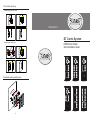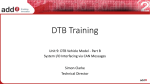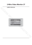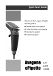
1
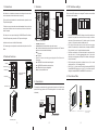
5. DIP Switches settings
JP-LK
To call the user, press a button with a associated nameplate of the user; then the
user will press the Unlock button on the monitor to open the door for the visitor if
she/he is accepted.
CN-LK
A ID card can be use to open the door.(Only for DMR12/ID series Door Station).
For detail ID card operation, please refer to DT system technical guide.
A exit button can be connect to the Door Station directly.
The Camera angle can be adjusted to coordinate the install position of the Door
Station
2. Parts and functions
Speaker
Camera Lens
Microphone
•
•
•
•
SET
Total 6 bits in the DIP switches can be configured. The switches can be modified
either before or after installation.
DIP
ON
This is a guide for quick installation. for more detail instructions, please refer to the
DT system technical guide.
T/R T/R+
DIP
RS-485
3
2
1
+12V
LK - (GND)
LK+(COM)
N.O.
EB EB+
L1
L2
BUS
+12V: 12VDC power output.
LK-(GND): power ground.
LK+(COM): electronical load activation ralay contact common.
NO.: electronical load activation ralay normally open contact(refer to DT technical
guide for Lock connection detail informations).
• EB+: Exit button.
• EB-: Exit buton.
• JP-LK: For electronic lock safety type setting(refer to Door Station Lock
Connections).
• T/R-: USB-RS485 communication terminal negative.
• T/R+: USB-RS485 communication terninal positive.
• SET: DIP switches for system configurations.
• Bus(L1,L2): non-polarised bus line.
Camera Angle
adjustment
ON
Door Station is a unit installed on the entrance of a building, which used to call a
user in a apartment, and control the electronic lock opening.
123456
3. Terminals
123456
1. Introductions
ON(1)
OFF(0)
ON
ON
• Bit-1 and Bit 2 is for door station ID settings, when mutil door stations are
installed in the system, these two bit must be set correctly, the first door
station set to 00, the second one set to 01, the third one set to 10, the fourth
one set to 11. If only one door station is installed, set to 00.
• Bit-3: Single line button door station or double line button door station
selection. If the door station is a double line button, for examlpe, the DMR12/
D16, set this bit to 0, set to 1 for single line button door stations.
• Bit-4: Button code selection; if use the default codes for each button of the
door station, set to 0, if use the programmed codes, set to 1.(the code for
each button can be program by the 2Easy+TOOL software, see the program
section in this manual)
• Bit-5: Unlocking time quick selection, by default it is set to 0, for 1 second
unlocking time; set to 1 for 5 seconds(by default).
• Bit-6: Set to 1,it is for door station ID settings,for examlpe,the DMR12/ID/
S4 and DMR12/ID/D8 must be set to 1;set to 0,it is not for door station ID
settings,for example,the DMR12/S8 and DMR12/D16 must be set to 0.
6. Place Name Plate
Name plate
4. Connections
Call button
This example is one door station wiring, note that the lock used here is a 12Vdc 300mA
power-to-unlock type. (please refer to DT technical guide for Lock connection detail
informations)
JP-LK
Electronic Lock
-
CN-LK
+
3
2
1
+12V
LK - (GND)
LK+(COM)
N.O.
EB EB+
L1
L2
BUS
1.Remove the bottom cover
2.Remove the anti-theft screw
Exit Button
Connect to DPS or DBC4S
With rainy cover
-1-
-2-
-3-
3.Extract name plate folder,
replace name plate.
7. Door station mounting
Mounting without rainy cover
2
1
Adjust camera angle
Install name plate
3
DT-ENG-DMR12-V1
4
DT 2-wire System
Mounting with rainy cover
1
2
Adjust camera angle
DMR12 Door Station
Quick Installation Guide
Install name plate
3
4
8. Installation with expanding panel
DMR12/S8
DMR12/D16
DMR12/ID/S4
DMR12/ID/D8
EP12/S12
EP12/D24
埋排线
-4-