1
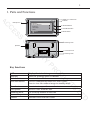
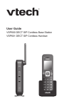
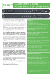
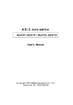
2-Wire Video Monitor 27
USER MANUAL
S
ES
C
AC
R
U
C
SE
Main Menu
1
2
3
i About
TS
C
U
D
O
PR
4
Y
IT
Monitor ...
Manual Monitor
Intercom
User Setup
Close
D
LT
1
1. Parts and Functions
C
AC
Main Menu
Microphone
Monitor ...
Manual Monitor
Intercom
User Setup
Close
1
2
S
ES
3
UNLOCK Button
TALK/MON Button
i About
4
MENU Button
SE
Speaker
Digital TFT LCD Screen
Indicator
Mounting Hook
BT1
BT2
EH
GND
VD
L1
123456
L2
Mounting Hook
Y
IT
R
U
C
Connection Port
DIPS
ON
Display the visitors' image
Show the working status of monitor
Press to release the door
Press to communicate hands free with visitor
Press to view the outdoor image in standby mode
Press twice to open the menu shortcuts
Receive voice from the user
8VHWR¿WWKHPRQLWRUWRWKHZDOO
Bus terminal
Send out voice from the visitor
TS
C
U
D
D
LT
Menu button
Microphone
Mounting hook
Connection port
Speaker
O
LCD screen
Indicator
Unlock button
Talk/Mon button
PR
Key functions
2
2. Monitor Mounting
S
ES
145~160 cm
C
AC
U
C
SE
IT
R
1. 8VHWKHVFUHZVWR¿[WKH0RXQWLQJ%UDFNHWRQWKHPRXQWLQJER[¿WWLQJDFFHVRULHV
LQFOXGHV D %UDFNHW 7ZR SLHFHV RI ; VFUHZV DUH QHHGHG IRU IDVWHQLQJ WKH
Mounting Bracket), Special 2 wire cables to connect with Monitor)
Y
2. :LUHWKHV\VWHPFRUUHFWO\VHHWKHODWHUFRQQHFWLRQFKDSWHUWKHQKDQJWKH0RQLWRU
RQWKH0RXQWLQJ%UDFNHW¿UPO\
O
PR
C
U
D
3. Main Menu
TS
1. Touch the screen anywhere on the monitor screen in standby mode, the date/time
SDJHZLOOEHVKRZQWKHGDWHWLPHSDJHZLOOFORVHLQPLQXWHLIQRRSHUDWLRQLV
made)
2. Touch the screen again, the main menu page will be shown as follows.
AM
Main Menu
Monitor ...
Manual Monitor
Intercom
User Setup
Close
i About
D
11 : 44
Fri.
LT
22/04/2011
3
%DVLF'RRU5HOHDVH2SHUDWLRQ
1. Press the CALL button on the door panel, the
Monitor rings and at the same time, the screen
displays the visitors' image.
DS-1
00:23
AC
S
ES
C
2. Press TALK/MON Button on the monitor
icon on the screen, you can
or touch
communicate hands free with the visitor for 90
seconds. Press TALK/MON button again or
icon to end the communication. If nobody answers the monitor, the screen
touch
will turn off automatically after 30 seconds.
SE
3. During the talking state, Press UNLOCK Button or touch
the corresponding door for the visitor.
or
icon to open
C
Y
IT
R
U
When the monitor is in standby mode, press TALK/MON %XWWRQ RU WRXFK
Monitor ... item on main menu page), The screen can display the view of outside.
icon to get into the camera switch
If multi door stations are installed, touch
PRGH RU GLUHFWO\ WRXFK Manual Monitor item on main menu page). You can
WRXFKFDPHUDWRPRQLWRUWKHGRRUSDQHORU&&79FDPHUD\RXUHTXLUH6HH
icon to end
WKHIROORZLQJGLDJUDPV3UHVV TALK/MON button again touch
monitoring.)
O
00:23
PR
DS-1
Monitor Select
C
U
D
Camera 1 ...
Camera 2 ...
Camera 3 ...
Camera 4 ...
Monitor Time Set ...
Exit
Home
TS
Intercom
Intercom Call ...
Inner Call ...
Direct Call Guard Unit ...
Exit
Home
D
Touch Intercom item on main menu page, there are
three items: Intercom Call...,Inner Call ...,Direct Call
Guard Unit...
NOTE: Guard Unit will not operate for single zone
video entry systems
LT
,QWHUFRP)XQFWLRQ
1. Intercom Call: User in one apartment can call
other apartments in the system. the code list will
be created automatically by the system. Touch
D FRGH QXPEHU \RX UHTXLUH RQ WKH VFUHHQ WKHQ
touch LFRQWRGLDO1RWH7RXFK icon again
to redial. 2.The DIP switch codes of each monitor
must be set using the Physical Code Method.)
Intercom Call
AC
[ 00 ]
[ 01 ]
[ 02 ]
[ 03 ]
[ 04 ]
[ 05 ]
Exit
The codes to the
left relate to the
code number
set for each
video monitor
Calling
Next Page
S
ES
C
SE
2. Inner Call: If multi slave monitors are installed in the same apartment, select Inner
Call, all the other Monitors will ring at the same time, whichever Monitor answers
the call, the conversation is started and the other monitors will stop ringing at the
VDPHWLPH1RWH7KH',3VZLWFKVHWWLQJVRIDOOPRQLWRUVPXVWEHVDPHPlease
refer to the DIP Switch Settings on page 7 for Logical Code Method)
IT
R
U
C
3. Direct Dial Guard unit: A Monitor can be assigned as Guard Unit Monitor; when
the Guard Unit Monitor answers the call, conversation with the guard person is
VWDUWHGThis facility is not available with single zone video entry systems).
6. Basic Setup Instructions
Y
Ring Tone Settings
PR
C
U
D
O
Touch User Setup item on the main menu page to enter the setup page. Touch Door
Station Call Tone, Inercom Call Tone or DoorBell Tone item, There are 12 ring tones
WKDWFDQEHVHOHFWHG7RXFKWKHULQJWRQHUHTXLUHGWKHQWRXFK LFRQWRVDYHDQGH[LW
WRXFK icon to cancel the setting and return to the last page, touch
icon to enter the
main menu page)
TS
Door Station Call Tone : Set the ring tone calling from the door panel.
Intercom Tone : Set the ring tone calling from other apartments/monitors.
DoorBell tone : Set the ring tone calling from a door bell.
Selected:
1 Carmen
2 Ding Dong
3 Rain
4 For Alice
Cancel
06
5 Sonatine
9 Do Re Me
6 Edelweiss
10 Happy Birthday
7 Going Home
11 Jingle Bells
8 Congratulation 12 Telephone Ring
D
Door Station Call Tone ...
Intercom Call Tone ...
DoorBell Tone ...
Clock ...
Next Page
Exit
Home
Door Station Call Tone
LT
User Setup (1)
Home
Save&Exit
Ring Volume and Night Ring Volume Setting
User Setup (2)
You can set a ring volume for day time and night
WLPHLQGLYLGXDOO\$030LVWKHGD\WLPH
DQG30$0LVWKHQLJKWWLPHE\GHIDXOW
if you don't want to be disturbed at night, you can set
the night ring volume to 0.
Touch User Setup item on the main menu page to
enter the setup page then touch Next Page item to
enter User Setup 2 page. Select Ring Volume Setting
or Night Ring Volume LWHP7RXFK Ÿ ź LFRQ WR
LQFUHDVHGHFUHDVHWKHYDOXH2QFHFRPSOHWHWRXFK
LFRQWRVDYHDQGH[LWWRXFK icon to cancel the
setting and return to the last page, touch
icon to
enter the main menu page)
C
AC
Ring Volume ...
Night Ring Volume ...
73&©&RQ½JXUH©©
Restore to default ...
Last Page
Exit
Home
S
ES
Ring Volume
SE
Current :
Home
Save&Exit
7. Date and Time Setting
Y
IT
R
U
C
Cancel
05
PR
Touch User Setup item on the main menu page to
enter setup page, touch Clock... item. a digital keypad
will be shown on the screen, input date and time by
touching the digital keypad and use * key to select
icon to
WKHVHWWLQJLWHP2QFHFRPSOHWHWRXFK
VDYHDQGH[LWWRXFK icon to cancel the setting and
return to the last page.)
Clock
D
O
2010 - 12 - 28
1 2
4 5
7 8
0
Cancel
Save&Exit
TS
C
U
8. Monitor Time setting
LT
Monitor Time Select
Current :
Cancel
Home
01min
Save&Exit
D
Touch Manual Monitor item on the main menu
page to enter the camera switch mode setting, select
Monitor Time Set... LWHP 7RXFK Ÿ ź LFRQ WR
LQFUHDVHGHFUHDVHWKHYDOXH2QFHFRPSOHWHWRXFK
LFRQWRVDYHDQGH[LWWRXFK icon to cancel the
setting and return to the last page, touch
icon to
enter the main menu page)
*
15 : 00
3
6
9
#
6
9. Restore to Default
S
ES
C
AC
Touch User SetupLWHPRQPDLQPHQXSDJHWRHQWHUVHWXSSDJHWKHQWRXFK1H[W3DJH
item to enter User Setup 2 page, touch Restore to default item, a message will be asked
WRFRQ¿UPWKHUHVWRUHRSHUDWLRQ,I\RXWRXFK icon, then all settings will be restored
to default, if you don't want to restore, touch LFRQWRFDQFHOWKHRSHUDWLRQ1RWHWKDW
the restore to default operation will not change the time setting and the date.)
User Setup (2)
Restore to Default
Ring Volume ...
Night Ring Volume ...
73&©&RQ½JXUH©©
Restore to default ...
Last Page
SE
Home
Restore all to default?
Cancel
OK
IT
R
U
C
Exit
Are you sure to
Y
10. Monitor Parameter Setting
Main Menu
Exit
Exit
*
2
5
8
0
3
6
9
#
Home
3.A digital keypad
will be shown.
D
How to set the monitor as a Guard Monitor
1
4
7
LT
2.Touch the screen
anywhere and hold for
2 seconds.
Input Code Number:[- - - -]
TS
1.Touch
item
on main menu page.
DT14-CT a1.3
V17.11.418.00
-------
C
U
i About
H/W :
S/W:
Local addr:
Unlock timing:
Unlock2 select:
Video standard:
Language:
D
Monitor ...
Manual Monitor
Intercom
User Setup
Close
O
PR
How to enter the installation setting page
A Monitor can be assigned as Guard Unit Monitor; when the Guard Unit Monitor
answers the call, conversation with the guard person is started.
7KHFRGHQXPEHURILVXVHGWRVHWWKHPRQLWRUDVDJXDUGXQLWPRQLWRUDQGLV
used to cancel this function.
This facility is not available with single zone video entry systems)
7
DIP Switch Settings - Logical Code Method
How to set the master and slave monitor address
AC
S
ES
C
$ PD[LPXP RI PRQLWRUV FDQ EH FRQQHFWHG LQ RQH DSDUWPHQW RQHPDVWHU PRQLWRU
together with 3 slave monitors, so you should set the code address correctly. (Note: You
must have one monitor set as a master monitor)
7KHFRGHRILVXVHGWRVHWWKHPDVWHUPRQLWRU
7KHFRGHRILVXVHGWRVHWWKH¿UVWVODYHPRQLWRU
7KHFRGHRILVXVHGWRVHWWKHVHFRQGVODYHPRQLWRU
7KHFRGHRILVXVHGWRVHWWKHWKLUGVODYHPRQLWRU
1RWH7RXFKEXWWRQWRFDQFHOWKHHQWU\WRXFKWRVDYHWKHVHWWLQJV
C
SE
U
How to set the date and time format
Y
IT
R
The system offers two methods of date and time
7KHFRGHQXPEHURILVXVHGWRVHWWKHGDWHIRUPDWDVPRQWKGDWH\HDU
7KHFRGHQXPEHURILVXVHGWRVHWWKHGDWHIRUPDWDVGDWHPRQWK\HDU
7KHFRGHQXPEHURILVXVHGWRVHWWKHWLPHIRUPDWDVKRXUV\VWHP
7KHFRGHQXPEHURILVXVHGWRVHWWKHWLPHIRUPDWDVKRXUV\VWHP
O
PR
How to set all of the monitors to display the visitor image
D
TS
C
U
In default mode when you receive a call, the master and slave monitors will ring at the
VDPHWLPHEXWRQO\WKHPDVWHUPRQLWRUZLOOGLVSOD\WKHLPDJHZKLOHWKHVODYHPRQLWRUV
FDQQRWKRZHYHUWKHVHWWLQJVFDQEHFKDQJHG\RXFDQVHWWKHPDVWHUPRQLWRUDQGDOO
the slave monitors to 'Panel On' to display the visitor image at the same time when
UHFHLYLQJDFDOOMXVWHQWHUWKHFRGHQXPEHURIRQHDFKVODYHPRQLWRU
LT
Press call button
on door panel
When reveiving a call, all monitors can display the image at the same time
D
1
1
1
1
2
2
2
2
3
3
3
3
4
4
4
4
Master monitor
#1st slave monitor
#2nd slave monitor
#3rd slave monitor
DIP Switch Settings - Physical Code Method
S
ES
C
AC
There are 6 DIP switches to the rear of each video monitor. The DIP switches are used to
configure the User Code for each monitor. Depending upon how many monitors you have,
if using a DBC4S unit or have any of the multi way DMR or 592 video entry systems, will
GHWHUPLQHKRZ\RXFRQ¿JXUHWKHXVHUFRGHXVLQJHLWKHUWKH/RJLFDORU3K\VLFDO&RGH0HWKRG
7KH/RJLDO&RGH0HWKRGZRXOGEHXVHGIRUDPD[LPXPRIPRQLWRUVLQRQHDSDUWPHQW7KLV
LVFRQ¿JXUHGE\HQWHULQJWKHInstallation Setting page of the video monitor and entering the
UHOHYDQWFRGHQXPEHUV
SE
R
U
C
7KH3K\VLFDO&RGH0HWKRGLVFRQ¿JXUHGE\VHWWLQJWKH',3VZLWFKHVWRWKHUHDURIHDFKYLGHR
monitor, typically this is required when installing any of the multi way DMR or 592 video entry
systems or if you have more than 4 monitors in one apartment (591 or 596 systems only)
Y
IT
NOTE for all multi way DMR and 592 video entry systems: You cannot have more than 4
monitors in one apartment
TS
C
U
D
O
PR
NOTE for 591 and 596 video entry systems: You can have more than 4 monitors in one
apartment
D
LT
For 591 and 596 video entry systems
Bit state
AC
ON
User Code
Bit state
Monitor 1
ON
1 2 3 4 5 6
C
Monitor 2
1 2 3 4 5 6
Monitor 3
S
ES
1 2 3 4 5 6
Monitor 4
1 2 3 4 5 6
ON
Monitor 7
ON
1 2 3 4 5 6
Monitor 9
Y
ON
IT
Monitor 8
R
1 2 3 4 5 6
U
ON
Monitor 6
C
1 2 3 4 5 6
Monitor 5
SE
1 2 3 4 5 6
Monitor 15
ON
1 2 3 4 5 6
ON
Monitor 14
ON
1 2 3 4 5 6
ON
Monitor 13
ON
1 2 3 4 5 6
ON
Monitor 12
ON
1 2 3 4 5 6
User Code
1 2 3 4 5 6
Monitor 10
1 2 3 4 5 6
C
U
D
1 2 3 4 5 6
Monitor 11
O
ON
PR
ON
Note: DIP switch 6 must be set to ON for all monitors if using a DBC4S unit
TS
D
LT
For 592 video entry systems
Bit state
User Code
Bit state
Code=0
AC
ON
C
Code=2
Code=3
ON
Code=4
SE
1 2 3 4 5 6
1 2 3 4 5 6
1 2 3 4 5 6
Code=18
ON
IT
Code=19
ON
1 2 3 4 5 6
1 2 3 4 5 6
ON
1 2 3 4 5 6
Code=30
Code=20
ON
Code=31
1 2 3 4 5 6
Code=21
C
U
D
O
Code=10
Code=29
1 2 3 4 5 6
PR
ON
Code=28
1 2 3 4 5 6
Y
Code=9
1 2 3 4 5 6
ON
Code=27
1 2 3 4 5 6
1 2 3 4 5 6
1 2 3 4 5 6
ON
ON
1 2 3 4 5 6
Code=8
ON
ON
Code=26
1 2 3 4 5 6
Code=17
R
1 2 3 4 5 6
ON
ON
1 2 3 4 5 6
ON
Code=25
1 2 3 4 5 6
1 2 3 4 5 6
Code=7
ON
ON
Code=16
U
Code=6
ON
Code=15
ON
Code=24
1 2 3 4 5 6
1 2 3 4 5 6
C
Code=5
ON
ON
1 2 3 4 5 6
ON
Code=23
1 2 3 4 5 6
Code=14
ON
1 2 3 4 5 6
ON
ON
1 2 3 4 5 6
1 2 3 4 5 6
Code=22
1 2 3 4 5 6
Code=13
ON
S
ES
ON
ON
1 2 3 4 5 6
1 2 3 4 5 6
User Code
1 2 3 4 5 6
Code=12
ON
Bit state
ON
1 2 3 4 5 6
Code=1
ON
Code=11
ON
1 2 3 4 5 6
User Code
Note: Monitors connected to button A must have a user code set from 0 to 15
Monitors connected to button B must have a user code set from 16 to 31
TS
DIP switch 6 must be set to ON for all monitors if using a DBC4S unit
D
LT
B
A
For multi way DMR 3 to 8 video entry systems
Bit state
C
AC
ON
User Code
Bit state
User Code
Bit state
User Code
Monitor 1
1 2 3 4 5 6
Monitor 2
S
ES
ON
1 2 3 4 5 6
ON
Monitor 3
1 2 3 4 5 6
ON
ON
Monitor 6
ON
1 2 3 4 5 6
1 2 3 4 5 6
Monitor 8
Y
ON
IT
Monitor 7
R
1 2 3 4 5 6
U
ON
Monitor 5
C
1 2 3 4 5 6
SE
1 2 3 4 5 6
Monitor 4
C
U
D
O
PR
Note: DIP switch 6 must be set to ON for all monitors if using a DBC4S unit
TS
D
LT
8
How to set the unlock parameter
Unlock mode:
AC
S
ES
C
7KHUHDUHWZRXQORFNPRGHVSRZHURQWRXQORFNW\SHXQORFNPRGH E\GHIDXOW
SRZHURIIWRXQORFNXQORFNPRGH The code number of 8010 is used to set the unlock mode to 0
The code number of 8011 is used to set the unlock mode to 1
SE
Unlock time:
IT
R
U
C
The unlock time can be changed at any time. It can be set from 1 to 9 seconds.
7KHFRGHQXPEHUIURPWRDUHXVHGWRVHWWKHXQORFNWLPHWRVHFRQGV
How to set the menu language
Y
8113: Russian
6ORYDNLD
+XQJUD\
8116: Czech
TS
C
U
8107: Portuguese
6&KLQHVH
7&KLQHVH
8110: Greek
8111: Turkish
8112: Polish
D
8101: English
8102: French
8103: Spanish
,WDOLDQ
*HUPDQ
8106: Dutch
O
PR
The monitor can support multi languages and it is so simple and fast, just input the
corresponding language code on the monitor. The language code number are as follows:
LT
D
1RWH7KHPRQLWRUFDQRQO\VXSSRUWW\SHVRIODQJXDJHV(QJOLVK)UHQFK6SDQLVK
DQG*HUPDQDUHGHIDXOW<RXFDQFXVWRPL]HDQ\ODQJXDJHVE\\RXUVHOI7KHODQJXDJH
which is unavailable will be set to English by default.
9
6FUHHQDQG9ROXPH$GMXVWPHQW
C
AC
During monitoring or talking, touch
icon, the ADJUST MENU will be displayed.
icon to decrease /
7RXFKDQGVHOHFWWKHDGMXVWPHQWLWHP\RXUHTXLUHWRXFK /
increase the value.
S
ES
1. 7KH¿UVWLWHPLV6FHQHPRGHVHOHFWLRQ7RWDORI
VFUHHQPRGHVFDQEHVHOHFWHGLQVHTXHQFHNormal,
User, Soft and Bright. Whenever you modify
Brightness or colour, Scene item will be set to User
mode automatically.
Scene
Bright
Color
Ratio
Talk Volume
Normal
6
6
16:9
2
Dec
SE
Exit
Inc
U
C
2. The Brightness and Colour item is for the image
TXDOLW\ VHWWLQJ DGMXVW WKH YDOXH WR JHW WKH EHVW
image you like.
3. The Ratio LWHPLVIRUVFUHHQGLVSOD\DGMXVWPHQW\RXFDQVHWWRRU
R
IT
The Talk Volume item is for talking volume adjustment.
Y
1RWHWKDWDOOWKHPRGLILFDWLRQVZLOOEHDFWLYDWHGLPPHGLDWHO\DIWHUWKHRSHUDWLRQ
Touch LFRQWRH[LWWKHDGMXVWSDJH
O
PR
C
U
D
6SHFL¿FDWLRQ
DC 24V
Ɣ Power consumption:
Standby:15mA; Working: 400mA
Ɣ Monitor screen:
7 Inch digital color LCD
Ɣ Display Resolutions:
800*3(R, G, B) x 480 pixels
Ɣ Video signal:
1Vp-p, 75Ω, CCIR standard
Ɣ Wiring:
2 wires, non-polarity
Ɣ Dimension:
125(H)×225(W)×23(D)mm
TS
Ɣ Power supply for indoor monitor:
D
LT