1
iLights
User Manual
Univeristy of Massachusetts
Senior Design Project 2009
Table of Contents
Installation and Usage
Set Up
pg. 3
Using iLights
pg. 3
iLights Plug-in (.dll file)
Added Files
Modified Files
pg. 4
pg. 4 – 12
Embedded Design (Arduinos)
Serial to Parallel converter
Hardware Control
pg. 12 – 14
pg. 14 – 17
2
iLights User Manual
Set Up
Installing Plug-in
To install the plug-in you must copy VizKit.dll into folder “C:\Program
Files\iTunes\Plug-ins\”. This file is names VizKit after the open source project it is based
upon. Do not change the name of this file as this may cause problems when running the
plug-in.
Driver
This project requires a driver for the USB to serial converter used to communicate
with the iLights hardware. To install this driver first attach the USB cable (the device
does not need to be turned on). The computer will recognize the device and ask if you
would like to locate the driver or let windows search for the driver. Select that you will
choose the location and direct the search to the “CDM 2.04.16 WHQL Certified” folder
contained in the iLights project directory. Windows will now install the proper driver.
There is one more step to make sure that the iLights plug-in can communicate
with the hardware. The driver you just installed creates a virtual COM port when the
USB cable is connected. This port must be labeled COM4 in order for the plug-in to find
the hardware. To do this go to “Start->My Computer”. Right click and select
“Properties”. From the “Hardware” tab, click the “Device Manger” button. Once in
“Device Manager” expand the “Ports (COM & LPT)” menu. Find “USB Serial Port
(COMx)” where x is the port number. If this says COM4 proceed to the next section. If
not follow these instructions.
Double click on “USB Serial Port (COMx)”. From the “Port Settings” tab click
the “Advanced” button. At the top there is a drop down list for “COM Port Number”.
Choose “COM4”.
Using iLights
Plug in iLights; if you have any lights plugged into the box they will turn on as follows:
Channels 1&2 full brightness, Channel 3 half brightness, Channel 4 off. This indicates
that the hardware is turned on. You may plug lights into the box at any time (on or off).
Next plug the USB cable into the computer. Open iTunes only after the USB cable has
been plugged into the computer. With iTunes open select “iLights” from the visualizer
menu. When you click “Show Visualizer” the iLights window will appear and the lights
will begin to react to the music. To select frequency ranges for the lights go to
“Visualizer Options”. A box will pop up with two tabs. Select the “Light Control” tab.
The interface is made up of 8 sliders, a low and high frequency cut for each channel.
Next to each slider the frequency for the slider position is displayed. Clicking save will
store your settings so that the will persist even after closing iTunes.
3
iTunes Plug-in (.dll file)
The iTunes plug-in is built as a Visual Studio C++ project. The project is based on
Vizkit [1] an open source platform for building and iTunes visualizer. This section will
deal with modifications we made to this project. For more information about the VizKit
project see http://www.imagomat.de/vizkit/.
Added Files
Serial.cpp: [2]
This file, and its header Serial.h, provide an easy to use interface for
transmitting/receiveing via a Windows serial port. They are from the Open Source
CSerial project. Documentation can be found at http://www.codeguru.com/cpp/in/network/serialcommunications/article.php/c2503.
User Input:
User input is taken via the Visualizer Options window. When the user clicks on this from
the iTunes drop down window a message is sent to our plug-in. This message is handled
in the same way as VizKit, by creating a Windows Dialog box. Our project ads a box for
light control, drawn in Visual Studio Resources editor. The resource file is called
IDD_DIALOG4. The handler for this Window is Light2Pane.cpp. This file is
commented. To understand general UI operation implemented see Microsoft’s MSDN
pages at http://msdn.microsoft.com/.
Modified Files
Main Folder
VisualMain.cpp:
-add serial initialization
-call iLightsSerial function on receiving renderFrame message
-iLightsSerial function added
This is the main function for the project. This file is called by iTunes and recognizes
messages defined by the iTunes Visualizer SDk documentation. The function
“iTunesPluginMain” is called when iTunes opens, and has been modified to open the
serial connection on COM4 at this point. The following code snippet contains this
function (lines 693 to 733).
OSStatus iTunesPluginMain(OSType message, PluginMessageInfo*
pluginMessageInfo, void* refCon)
#endif
{
OSStatus status;
switch (message) {
case kPluginInitMessage:
4
pluginMessageInfo->u.initMessage.options =
kPluginWantsDisplayNotification;
status =
VisualMain::RegisterVisualPlugin(pluginMessageInfo);
break;
case kPluginCleanupMessage:
status = noErr;
break;
case kPluginPrepareToQuitMessage:
status = noErr;
break;
default:
status = unimpErr;
break;
}
// Attempt to open the serial port (COM4)
serial.Open(_T("COM4"));
// Setup the serial port (38400,N81) handshake off
serial.Setup(CSerial::EBaud38400,CSerial::EData8,CSerial::EParNone,CSer
ial::EStop1);
serial.SetupHandshaking(CSerial::EHandshakeOff);
// The serial port is now ready and we can send/receive data. If
//reload saved values
reloadLightSettings();
return status;
}
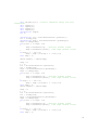
Also added to this method is the “iLightsSerial” function. This is the method
responsible for calculating the average power contained in each user-selected range,
packaging the data as an ANSI string, and writing it to the COM port. The code
(lines 577 to 672) responsible is the following snippet.
void iLightsSerial(UInt8 *renderData)
{
SInt16
SInt32
index;
channel;
if (renderData == nil)
{
return;
}
5
char iLights[9]=""; //need "" otherwise string "not null
terminated"
char light1[3];
char light2[3];
char light3[3];
char light4[3];
unsigned int temp=0;
int i;
unsigned int low = VisualPreferences::getC1Low();
low = lookUp[low];
unsigned int high = VisualPreferences::getC1High();
high = lookUp[high];
for(i=low; i <= high; i++)
{
temp +=renderData[i]; //sum left channel values
temp +=renderData[i+512]; //sum right channel values
}
if(high + 1 - low !=0)
temp = temp /(2*(high + 1 - low))>>2;
else temp = 0;
UInt8 number1 = (UInt8)temp;
temp = 0;
i = 0;
low = VisualPreferences::getC2Low();
low = lookUp[low];
high = VisualPreferences::getC2High();
high = lookUp[high];
for(i=low; i <= high; i++)
{
temp +=renderData[i]; //sum left channel values
temp +=renderData[i+512]; //sum right channel values
}
if(high + 1 - low !=0)
temp = temp /(2*(high + 1 - low))>>2;
else temp = 0;
UInt8 number2 = (UInt8)temp;
temp = 0;
i = 0;
low = VisualPreferences::getC3Low();
low = lookUp[low];
high = VisualPreferences::getC3High();
high = lookUp[high];
for(i=low; i <= high; i++)
{
temp +=renderData[i]; //sum left channel values
temp +=renderData[i+512]; //sum right channel values
}
if(high + 1 - low !=0)
temp = temp /(2*(high + 1 - low))>>2;
else temp = 0;
6
UInt8 number3 = (UInt8)temp;
temp = 0;
i = 0;
low = VisualPreferences::getC4Low();
low = lookUp[low];
high = VisualPreferences::getC4High();
high = lookUp[high];
for(i=low; i <= high; i++)
{
temp +=renderData[i]; //sum left channel values
temp +=renderData[i+512]; //sum right channel values
}
if(high + 1 - low !=0)
temp = temp /(2*(high + 1 - low))>>2;
else temp = 0;
UInt8 number4 = (UInt8)temp;
//sptrintf is similar to printf but prints to a char* %.2d will
pad with 0s, makes sure all values 2 chars
sprintf_s(light1, "%.2d", number1);
sprintf_s(light2, "%.2d", number2);
sprintf_s(light3, "%.2d", number3);
sprintf_s(light4, "%.2d", number4);
//put together string to transmit
strcat_s(iLights,9,light1);
strcat_s(iLights,9,light2);
strcat_s(iLights,9,light3);
strcat_s(iLights,9,light4);
serial.Write(iLights);
}
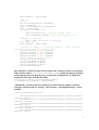
This function is called each time iTunes requests the visualizer frame to be updated.
When iTunes sends a “kVisualPluginRenderMessage” it hands the plug-in a pointer
to information about the playing song. At this time “iLightsSerial” is called and
handed the FFT data with this line (380):
iLightsSerial((UInt8*)visualPluginMessageInfo>u.renderMessage.renderData->spectrumData);
Additionally, a function has been added to the main function which is called on
startup to reload stored user settings. This function, “reloadLightSettings” is lines
674-684.
void reloadLightSettings(void)
{
VisualPreferences::setC1Low(VisualPreferences::getValue(VisualPre
ferences::c1Low));
VisualPreferences::setC1High(VisualPreferences::getValue(VisualPr
eferences::c1High));
VisualPreferences::setC2Low(VisualPreferences::getValue(VisualPre
ferences::c2Low));
VisualPreferences::setC2High(VisualPreferences::getValue(VisualPr
eferences::c2High));
VisualPreferences::setC3Low(VisualPreferences::getValue(VisualPre
ferences::c3Low));
7
VisualPreferences::setC3High(VisualPreferences::getValue(VisualPr
eferences::c3High));
VisualPreferences::setC4Low(VisualPreferences::getValue(VisualPre
ferences::c4Low));
VisualPreferences::setC4High(VisualPreferences::getValue(VisualPr
eferences::c4High));
}
VisualPreferences.cpp:
-Added persistant preferences for light control settings
-Added int values for light control settings for quick lookup
by “iLightsSerial” function
-Added get/set methods for these int values
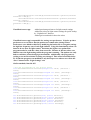
VisualPreferences.cpp is responsible for storing user preferences. It backs up these
preferences to a text file so that the preferences remain after closing iTunes.
Preferences were added to this file by modifying the header file to recognize settings
for high/low frequency cuts of each light channel. Using this functionality alone was
found to be too slow for light control. Each time the lights were updated the
program needed to read the values from a text file. Because of this int values were
added to store the light settings while the program is running. The update now only
had to read these values through get int methods. Additionally, the program was
writing to a text file each time a setting was changed. This caused a noticible delay.
To fix this the program was modified to only back up to text when a user clicks the
“Save” button on the “Light Settings” tab.
Get/Set methods, lines 90-107:
//Set and get methods for int storage values
void VisualPreferences::setC1Low(unsigned int value) {intc1Low =
value;}
void VisualPreferences::setC1High(unsigned int value) {intc1High
value;}
void VisualPreferences::setC2Low(unsigned int value) {intc2Low =
value;}
void VisualPreferences::setC2High(unsigned int value) {intc2High
value;}
void VisualPreferences::setC3Low(unsigned int value) {intc3Low =
value;}
void VisualPreferences::setC3High(unsigned int value) {intc3High
value;}
void VisualPreferences::setC4Low(unsigned int value) {intc4Low =
value;}
void VisualPreferences::setC4High(unsigned int value) {intc4High
value;}
int
int
int
int
int
int
=
=
=
=
VisualPreferences::getC1Low(void) {return intc1Low;}
VisualPreferences::getC1High(void) {return intc1High;}
VisualPreferences::getC2Low(void) {return intc2Low;}
VisualPreferences::getC2High(void) {return intc2High;}
VisualPreferences::getC3Low(void) {return intc3Low;}
VisualPreferences::getC3High(void) {return intc3High;}
8
int VisualPreferences::getC4Low(void) {return intc4Low;}
int VisualPreferences::getC4High(void) {return intc4High;}
VisualConfiguration.cpp:
-Set Plugin name to “iLights”
The only change to this file was to change the plug-in name from VizKit to iLights when
it shows up in the iTunes Visualizer menu. Lines 49-59:
// ========= INDIVIDUAL VISUALIZER IDENTIFICATION CONFIGURATION (start)
========= //
const char* const VisualConfiguration::visualizerPluginIdentifierName =
"iLights";
const char* const VisualConfiguration::visualizerShowName = "iLights";
void VisualConfiguration::prepareVisualizerShowNameUnicode() {
#if TARGET_OS_WIN
wchar_t* visualizerShowNameUnicode_wchar = L"iLights"; // utf-16
this->visualizerShowNameUnicode =
(uint16*)visualizerShowNameUnicode_wchar;
#endif
Ensemble Folder
VisualStageControl: -Turn off all visual actors except ProcessMonitor
VisualStageControl is responsible for calling the visual actors to be displayed in the
stage, or iTunes visualizer window. More about this can be found in the VizKit [1]
documentation. We modified this file by commenting out all of the lines that called
actors except ProcessMonitorActor which we modified into our iLights display.
Actions Folder
ProcessMonitor: -Turn off all parts except debug info and spectrum analyzer
For iLights we wanted to display a spectrum analyzer to aid the user in choosing
frequency bands to control lights. This actor already had a spectrum analyzer, albeit
smaller and in lower resolution than we liked. It also had useful debug info such as frame
rate (also the rate our lights are updated) so we kept this information. We modified this
file by comenting out lines calling additional components of the actor. Actual drawing of
these parts is handled in VisualGraphics.cpp.
9
Graphics Folder
VisualGraphics:
-Modify “drawSpectrumAnalyzer” function to draw a large,
centered, and higher resolution analyzer
This file was only changed to modify features of the existing, VizKit [1] spectrum
analyzer. The modified code (lines 1587 – 1681):
void VisualGraphics::drawSpectrumAnalyzer(const sint16 currHistoryNum,
const uint16 numberOfHistories, const uint32 numberOfSpectrumEntries,
const uint16 numberOfAudioChannels, const uint8*** const
spectrumDataArray, const VisualCamera& aCamera) {
if (currHistoryNum == -1) return;
GLdouble xPos;
GLdouble yPos;
GLdouble coordWidth;
GLdouble coordHeight;
uint16 index, i, k;
GLdouble spectrumVal;
uint16 numberOfSubBands = 50;
float* spectrumDataSubBands;
float maxSpectrumSum = 0;
uint32 numberOfEntriesPerBarGraph;
uint16 numberOfBlocksPerBarGraph = 20;
GLdouble heightOfCell; // heightOfCell = heightOfBlock +
heightOfGapBetweenBlocks
GLdouble heightOfBlock;
GLdouble heightOfGapBetweenBlocks;
GLdouble widthOfCell;
GLdouble widthOfBlock;
spectrumDataSubBands = (float*)malloc(numberOfSubBands *
sizeof(float));
for (i = 0; i < numberOfSubBands; i++) {
spectrumDataSubBands[i] = 0.0f;
}
numberOfEntriesPerBarGraph = numberOfSpectrumEntries / 2 /
numberOfSubBands;
// position on screen
coordWidth = this->xPixelToCoord(800, aCamera);
coordHeight = this->yPixelToCoord(250, aCamera);
heightOfCell = coordHeight / (float)numberOfBlocksPerBarGraph;
heightOfBlock = heightOfCell * 0.8;
heightOfGapBetweenBlocks = heightOfCell * 0.2;
widthOfCell = coordWidth / (float)numberOfSubBands;
widthOfBlock = widthOfCell * 0.9;
xPos = aCamera.getMaxRightCoord() - coordWidth;
xPos -= this->xPixelToCoord(250, aCamera);
glLineWidth(1.0f);
10
glColor3d(1,1,1);
glLoadIdentity();
glPointSize(1.0f);
glTranslated(0.0, aCamera.getMaxBottomCoord() + this>xPixelToCoord(10, aCamera), 0.0);
// collect values for each subBand
index = 0;
for (i = 0; i < (numberOfSpectrumEntries / 2); i++) {
if ((i > 0) && (i%numberOfEntriesPerBarGraph == 0))
index++;
if (index < (numberOfSubBands - 1)) {
//spectrumDataSubBands[index] +=
(float)spectrumDataArray[currHistoryNum * numberOfAudioChannels *
numberOfSpectrumEntries + i + 0]; // channel 0
spectrumDataSubBands[index] +=
(float)spectrumDataArray[currHistoryNum][0][i]; // channel 0
//spectrumDataSubBands[index] += (float)10;
}
}
for (i = 0; i < numberOfSubBands; i++) {
if (spectrumDataSubBands[i] > maxSpectrumSum) {
maxSpectrumSum = spectrumDataSubBands[i];
}
}
for (i = 0; i < numberOfSubBands; i++) {
spectrumDataSubBands[i] = spectrumDataSubBands[i] /
maxSpectrumSum; // maximum value 1.0
}
glEnable (GL_BLEND);
glBlendFunc (GL_SRC_ALPHA, GL_ONE_MINUS_SRC_ALPHA);
glBegin (GL_QUADS);
for (i = 0; i < numberOfSubBands; i++) {
spectrumVal = spectrumDataSubBands[i];
for (k = 0; k < numberOfBlocksPerBarGraph; k++) {
if ((spectrumVal * coordHeight) > (k * heightOfCell))
{
glColor4d(1, 1, 1, .8);
} else {
glColor4d(0.8, 0.8, 0.8, 0.1);
}
yPos = (float)k * heightOfCell +
(float)heightOfGapBetweenBlocks+this->xPixelToCoord(150, aCamera);
glVertex2d(xPos, 0.0 + yPos);
glVertex2d(xPos + widthOfBlock, 0.0 + yPos);
glVertex2d(xPos + widthOfBlock, 0.0 + yPos +
heightOfBlock);
glVertex2d(xPos, 0.0 + yPos + heightOfBlock);
}
xPos += widthOfCell;
11
}
glEnd();
glDisable (GL_BLEND);
free(spectrumDataSubBands);
}
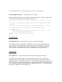
Embedded Programming
The system uses two microcontrollers which must be programmed using an Arduino
prototyping board. The microcontrollers must be removed from the PCB if they are to be
re-programmed. The code is written using Arduino type syntax which provides several
nice functions and method calls but also accepts the user to write C code.
The link from the pc to the microcontroller that triggers the switching circuitry is
composed of two parts: one Arduino prototyping board with an Atmega168 that has been
programmed to read the serial port data and another which has been programmed for
triggering the triac circuits. The first microcontroller receives a string, at 38400 baud,
which contains 6 bit values for each of the four channels. These values represent the
average power across the particular frequency band. This data is stored until the second
Arduino requests new values. At this point the data is transmitted over ports B and C of
the Atmega168 used as parallel ports. Parallel data is sent extremely fast since only
bitwise data is needed, and this allows for efficient communication of our signals. Using
two ports allows us to send update data for two channels simultaneously, meaning it only
takes two transmissions to send all four values.
The second microcontroller receives our parallel data and converts it into dimming delays
using a lookup table. This table is scaled in a logarithmic manner in order to match
human perception of brightness. The dimming is accomplished using a critically timed
loop to properly set the phase delay at which to trigger each channel. This loop is run
approximately 1300 times over every full 120Hz AC signal, which was discovered
empirically. To dim the lights to the specified level we simply run this loop a certain
number of times, determined by the proper value from the lookup table, before sending
the signal to trigger the power for that channel. This gives us a very consistent way to
maintain phase control. Communicating with our pc in this way has allowed us to
continuously send updating signals to each of the four lights at around 80 times a second
without any visual delay between the music and the properly dimmed lighting.
Source Code
First Microcontroller (serial to parallel converter)
//iLights - Serial to parallel converter
//(originated 2-3-2009 by Chris Merola)
//modified 2-27-09 to receive ANSII string input
//modified 3-2-09 to use 2 simultaneous data buses PORTB and PORTC
unsigned long serialData = 0;
the serial port
channel.
//variable to store the data from
//32 bits 4 8bit blocks, one for each
only lower 6 bits are used due to port access limitation
12
int dataReady = 2;
//use pin 2 to signal data ready to 2nd Arduino
int nextValue = 3;
//use pin 3 to receive data ready signal from
Arduino
byte brightness[4] = {0,0,0,0};
byte temp;
int transmit = 0;
int sync = 4;
void setup() {
DDRB = DDRB | B00111111;
//set Port B pins 0-5 as output BUS1
DDRC = DDRC | B00111111;
//set Port C pins 0-5 as output BUS2
Serial.begin(38400);
//connect to the serial port
pinMode(dataReady, OUTPUT); //set data ready pin output
pinMode(nextValue, INPUT); //set next value trigger input
pinMode(sync,OUTPUT);
digitalWrite(dataReady, LOW); //no data ready
PORTB = B00000000;
//ditigalWrite(nextValue, HIGH); //decide if pull up resistor
necessary
}
void loop () {
if(Serial.available()>0) //may have to set ready for 32 bit long
{
delay(3);
//serialData = Serial.read();
// read the serial port
temp = (Serial.read()-48)*10;
temp = Serial.read()-48 + temp;
brightness[0] = temp;//(byte)serialData; //Serial.read() reads one
byte at a time (returns -1 if no data)
temp = (Serial.read()-48)*10;
temp = Serial.read()-48 + temp;
brightness[1] = temp;//(byte)(serialData>>8);
temp = (Serial.read()-48)*10;
temp = Serial.read()-48 + temp;
brightness[2] = temp;//(byte)(serialData>>16);
temp = (Serial.read()-48)*10;
temp = Serial.read()-48 + temp;
brightness[3] = temp;//(byte)(serialData>>24);
Serial.read();//read null-termination character from transmitted
string
transmit = 1;
}
switch (transmit)
{
case 0: break; //nothing to send
case 1:
//send first two values
PORTB = brightness[0];
PORTC = brightness[1];
digitalWrite(sync, HIGH); //sets count on arduino 2 to 0.
transmission.
digitalWrite(dataReady, HIGH); //data ready
if (digitalRead(nextValue))
{
syncs
13
digitalWrite(dataReady, LOW); //arduino 2, do not read data
digitalWrite(sync, LOW);
transmit = 2;
}
break;
case 2:
//send second two values
PORTB = brightness[2];
PORTC = brightness[3];
digitalWrite(dataReady, HIGH); //data ready
if (digitalRead(nextValue)==0)
{
digitalWrite(dataReady, LOW); //arduino 2, do not read data
transmit = 0;
}
break;
default:
break;
}
}
Second Microcontroller (triac control)
//iLights - Code for the triac triggering microcontroller
//(originated 2-3-2009 by Chris Merola)
//tested 2-7-09 with parallel input generated on dip switches
//modified 3-2-09 to take inputs on 2 buses PORTB and PORTC
//sped up timing so that all data is read and processed in
//one zero cross cycle!!!
//the pin which detects zero-crossing of live AC signal
int zeroCross = 2;
//The 4 output
int trigger1 =
int trigger2 =
int trigger3 =
int trigger4 =
channels to be triggered
4;
5;
6;
7;
byte count = 0;
int input = 0;
int maxDelay = 1300; //1500 is as dim as you need to get
volatile int i = 0;
volatile int state = 0;
volatile char temp;
char up = 0;
char down = 0;
unsigned int brightness[4] = {0, 500, 1000, 1500};
//The lookup table with scaled values to provide a nonlinear dimming
scale
14
unsigned int lookup[64] =
{1300,1300,1300,1300,1300,1298,1298,1298,1298,1297,1297,
1297,1296,1296,1295,1295,1294,1293,1293,1291,1290,
1289,1288,1286,1285,1283,1280,1278,1276,1273,1270,
1266,1262,1257,1252,1246,1240,1232,1224,1215,1205,
1194,1181,1167,1150,1132,112,1090,1064,1036,1004,
968,928,883,833,777,714,643,564,475,376,265,140,0};
void setup()
{
DDRB = DDRB & B11000000;
brightness values] BUS1
DDRC = DDRC & B11000000;
light number values] BUS2
DDRD = B11110010;
ready], pin1 output [switch
// run once, when the sketch starts
// sets port B pins 0-5 as input
[parallel
// sets port C pins 0-5 as input
[parallel
// sets port D pin0 input [High when data
when data read],
// pin2 input for zero cross detection, pin
3 input for reset count, pins4-7 output [triac triggers] pin7 not used.
// Note: pins 4-7 set high when this
microcontroller is reset. (lights on)
attachInterrupt(0,crossDown,FALLING); //interrupt on pin2 calls cross
at falling edge
}
void loop()
// runs over and over again
{
//On zero cross trigger, handle dimming of lights.
//Waits delay = brightness[i], which is a portion of the entire ac
half-cycle, and then triggers appropriate channel
if(up)
{
triggerLights();
attachInterrupt(0,crossDown,FALLING);
up = 0;
if(digitalRead(0)) parallelIn(); //after handling critical timing
operations check/read parallel data from other arduino
}
//same as above statement for switch High->Low
if(down)
{
triggerLights();
attachInterrupt(0,crossUp,RISING);
down = 0;
if(digitalRead(0)) parallelIn(); //after handling critical timing
operations check/read parallel data from other arduino
}
}
//Responsible for triggering lights with correct timing
void triggerLights()
15
{
i=0;
while(i<maxDelay)
{
if(i == brightness[0])
if(i == brightness[1])
if(i == brightness[2])
if(i == brightness[3])
i++;
}
for(i=3; i < 8; i++)
{
digitalWrite(i,LOW);
}
digitalWrite(trigger1,HIGH);
digitalWrite(trigger2,HIGH);
digitalWrite(trigger3,HIGH);
digitalWrite(trigger4,HIGH);
}
void parallelIn() //read parralel inputs
{
//if(digitalRead(3)>0) count = 0; //this bit high when first byte
sent ::SYNC COUNTERS::
brightness[0] = lookup[PINB];
brightness[1] = lookup[PINC];
digitalWrite(1,HIGH);
//switch pin telling other
arduino to make next value vailable
delay(1);
while(1)
{
if (digitalRead(0)) break;
}
brightness[2] = lookup[PINB];
brightness[3] = lookup[PINC];
digitalWrite(1,LOW);
//switch pin telling other
arduino to make next value vailable
}
//next two funtions handle interupts when reciveing Low->High or High>Low triggers
//used two methods because each one confirms cross by confirming the
trigger 5 times
void crossDown() //Low->High
{
for(temp = 0; temp<5 ;) //check to see that pin is low 5 times for
confirmation
{
if(digitalRead(zeroCross) == LOW)
temp++;
else temp = 20;
}
if (temp != 20)
{
down = 1; //set flag, event handled in loop()
}
}
void crossUp()
//High->Low
16
{
for(temp = 0; temp<5 ;) //check to see that pin is high 5 times for
confirmation
{
if(digitalRead(zeroCross) == HIGH)
temp++;
else temp = 20;
}
if (temp != 20)
{
up = 1; //set flag, event handled in loop()
}
}
References
[1] Wichmann, Heiko. "Open Source iTunes Visualizer: VizKit." Imagomat. 1 Apr.
2009. 3 May 2009 <http://www.imagomat.de/>.
[2] Archer, Tom, and Rick Leinecker. "CSerial - A C++ Class for Serial
Communications."
CodeGuru.
7
Aug.
1999.
3
May
2009
<http://www.codeguru.com/>.
17