1
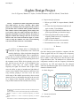
Draft Report
1
iLights Design Project
Jose D. Figueroa, Matthew C. Ryder, Nicholas Wittemen, and Chris Merola, Team Soules
A. Requirement Specifications
1. Deliver up to 500W X 4 output channels, 2000W
max.
2. Go from off to fully illuminated and back off
again in under 75ms (800bpm).
3. Lights to be fully illuminated within 80ms of
audio input (Human sync detection range).
4. iTunes plug-in that allows users to select
frequency band between 20 - 20,000Hz as
trigger for each channel.
5. USB 1.0 link to Arduino microcontroller.
6. Documented source code + user manual
II. DESIGN
I. INTRODUCTION
problem our design solves is eliminating the
constraint of light visualizations from iTunes and
actually displaying a light visualization through the
control of incandescent lights. This is a problem for
people who are visually stimulated. Users would like to
be able to bring their songs to life and bring them out of
the computer screen. While devices already exist to do
this, they do not give the user a GUI (Graphical User
Interface) where they can control which audible
frequency the lights will interact with. iLights allows
users the ability to plug in incandescent light bulbs of
various colors and have them interact to the beat of the
song currently playing in real time. Users can select
which range of the audible spectrum they what a certain
channel to react to, and through the plug in the user will
see a display of the frequency spectrum output of the
song to allow band selection to be done more easily.
HE
T
A. System Overview
Our basic design system includes a computer with the
iTunes program and our GUI along with a frequency
analyzer. From a USB output on the computer, we will
have a USB 1.0 cable that will tie into the input of the
iLights Hardware Box. The hardware box contains the
components needed to take the frequency information
provided by our GUI and control the four channels
where the incandescent lights will be connected to. Each
channel will handle 500W.
B. Block Diagram
User
GUI
USB Link
Arduino microcontroller
Frequency
Analyzer
Triac
Triac
Triac
Triac
iTunes
Manuscript received November 20, 2008. This work was supported in part
by SDP 2009.
Jose D. Figueroa is a senior in Electrical Engineering at UMASS Amherst
Matthew C. Ryder is a senior in Electrical Engineering at UMASS
Amherst
Nicholas Wittemen is a senior in Electrical Engineering at UMASS
Amherst
Chris Merola is a senior in Electrical Engineering at UMASS Amherst
PC
C. System Specification
iTunes interface
External AC lights/power strips
iLights Hardware Box
Abstract— People listen to music using iTunes more than
most media players out there currently. Most media
players have visualizers that can be placed on the screen to
give the music more excitement. There problem with this is
that visualizer software limits lighting effects simply to the
screen and no where else. Light controllers exist, but for a
high price and with no easy-to-use interface. We propose a
plug-in for iTunes that would give the user an easy-to-use
interface that will control incandescent lights of various
colors to bring the visualizer out of the screen and bring
color and excitement to the user’s environment.
Draft Report
Our software must be able to communicate with
iTunes in order to control lights based on the music
being played. The software will also allow the user to
select frequency ranges that will control each iLights
electrical outlet. From data extracted with iTunes we
will determine the power contained in a number of user
selected frequency bands and use this to set the
amplitude of the connected lights. Due to the physical
properties of triacs, the fastest we can adjust the power
sent to our lights is 120 times per second. This is the
rate at which we will retrieve audio spectrum
information form iTunes. This data will be updated and
packaged to be sent via USB to our hardware
continuously. As of this time we are able to extract
frequency data from iTunes and display a spectrograph
of the audio file being played.
To extract frequency data we use the software
development kit released by apple for visualization
development. Using this we implement a Dynamic Link
Library, call a *.dll file, which can access frequency data
through iTunes provided variables. iTunes does a FFT
(Fast Fourier Transform) of the audio being played and
makes available the power contained in 256 samples
spaced linearly from 20 Hz to 20kHz. The data is
provided is of type Uint8 giving 256 steps of resolution.
OpenGL is used to display this data graphically,
specifically a package named freeglut. We have chosen
this package because is built to be both easy to
implement and extremely portable; although we are
developing in Windows we would like to be able to port
our software to OSX. At this time we are displaying a
level bar for each of the 256 available bands. Our code
controls the bar height using a log scale in order to
compare power in the same way as the human ear.
As of now our software is able to communicate
with iTunes, extract the frequency spectrum of the audio
being played, and display this information graphically.
The next step will be to implement a user interface. We
will use handlers available in the freeglut package to do
this. We have already experimented with input using
this package and have determined that it will be able to
handle the input our project requires.
Serial Port Communication Link
The link from the pc to the microcontroller that
triggers the switching circuitry is compromised of 2
2
parts: C++ code which translates and transmits the
extracted frequency data over the serial port; and an
Arduino prototyping board with an Atmega168 that has
been programmed to read the serial port data and
interpret it into control instructions for triggering the
triac circuits.
The extracted frequency data will consist of 256
samples of the audible frequency range, and the user will
specify 4 different spans of this frequency band they
want their 4 lights to react to. The power over each of
these frequency bands will provide the output control
signal to be written to the serial port. To send these 4
signals simultaneously we will have to store them in an
array and write the whole array to the serial port. This
writing must occur at the same rate we set the Arduino
board to operate at. Currently a baud rate of 19200 has
been used consistently in our code. The microcontroller
will then read the serial port and take the 4 individual
elements of this array and translate the power over each
frequency band into the appropriate phase control.
Phase control works by turning on a fraction of each
half wave; current through the load is proportional to the
area under this portion of the sine wave. The Arduino
determines when to trigger each triac and turn on this
signal to provide phase control. This is done using the
Arduino to detect zero-crossings which, since our ac
power is mostly constant at 120 Hz, will remain at
approximately 1/120 seconds apart. This data will
continuously be collected, allowing us to accurately
switch on during the desired phase of the pulse, resulting
in real-time phase control of the 4 incandescent lights.
Jose’s Hardware part
The triac switching circuit utilizes a snubberless triac
in order to obtain the switching capabilities for the AC
power. The snubber circuit is mostly applicable for
inductive load situations, which will not be the typical
case here where we expect resistive loads. There exist
several different circuit configurations from which the
most suitable was customized to our needs based on
performance and power handling.
Matt’s part
Text.
Draft Report
3
D. Design Alternative
We have considered other alternatives in the case that
something may not work as originally planned. Reasons
we would need alternatives would be if iTunes SDK is
inadequate. In this case we have considered the
possibility of using alternative media players such as
Winamp open-source or VLC media player.
The second design alternative would be replacing the
triac if it is found not to be the best way for controlling
the lights. Silicon-controlled rectifier (SCR) could be
another solution for better switching and control of
lights. We could also choose Resistive Dimming by
rectifying AC to DC and using different lights. However
this could limit the amount of power we would be able
to switch due to heat emission.
III. MDR PROTOTYPE IMPLEMENTATION
A. System Overview
Please check with your editor on whether to submit
your manuscript as hard copy or electronically for
review
IV. PROJECT MANAGEMENT
A. System Overview
Our team as split the project up into four main areas:
Chris Merola is responsible for designing the easy-touse GUI along with the iTunes plug-in with iTunes SDK
to extract frequency information. He is also charged with
making the software compatible for both Mac and PC
operating systems.
Nicholas Wittemen has been progressively developing
a serial communications link with C++ and the
processing language to make data transfer possible
between the iTunes software plug-in and the Arduino
microcontroller that will drive the triggers for the triacs
in order to control the lights appropriately.
Jose D. Figueroa has been assigned to designing the
triac circuit which will handle 4 x 500W, 2000W total,
and taking all safety precautions when interfacing with a
live AC source. He is also the webmaster who is
responsible for updating and maintaining Teams Soules’
website.
Matthew C. Ryder as been doing research on EMI
(Electromagnetic Interference) so that our product not
only functions properly within its contained environment
but that it also meets all FCC regulations and safely
interfaces with normal consumer electronics in a home
with out effecting or causing damage to other products.
V. SUMMARY AND CONCLUSIONS
A. System Overview
Please check with your editor on whether to submit
your manuscript as hard copy or electronically for
review. References
B. System Overview
Please check with your editor on whether to submit
your manuscript as hard copy or electronically for
review.
*
Jose’s book + triac datasheets
Nick’s blog sites + Arduino.cc + Freeduino
Chris’s open GL book + zero-crossing datasheets