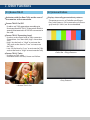
1
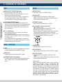
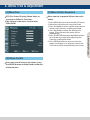
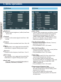
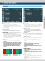
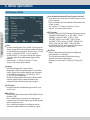
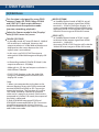
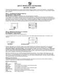
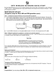
5.5” FHD Multi Format
Viewfinder Monitor
Operation Manual_ver 1.1
VFM-058W
1. Caution .............................................................................
2. Main Features .....................................................................
3. Controls & Functions ............................................................
4. Menu Tree & Adjustment........................................................
5. Menu Operations .................................................................
[1] Picture ..........................................................................
[2] Color ............................................................................
[3] Marker ..........................................................................
[4] Display / Video ................................................................
[5] Waveform ......................................................................
[6] Audio ...........................................................................
[7] System .........................................................................
6. Button Functions..................................................................
7. Other Functions ...................................................................
8. Available Signal Formats .......................................................
9. Product Specifications ..........................................................
10. Optional Accessories..........................................................
04
06
07
09
10
10
10
11
12
14
17
18
19
20
30
31
32
FCC (Federal Communications Commission)
This equipment has been tested and found to comply with the limits for class A digital device, pursuant to part 15
of the FCC Rules. These limits are designed to provide reasonable protection against harmful interface when the
equipment is operated in a commercial environment.
This equipment generates, uses and can radiate radio frequency energy and if not installed and used in
accordance with the instruction manual, may cause harmful interference to radio communications. Operation of
this equipment in a residential to correct the interference at his own expense
CAUTION: Change or modifications not expressly approved by the manufacturer responsible for compliance
could void the user’s authority to operate the equipment.
Disposal of Old Electrical & Electronic Equipment
(Applicable in the European Union and other European countries with separate collection systems)
This symbol on the product or on its packing indicates that this product shall not be treated as household
waste. Instead it shall be handed over to the applicable collection point for the recycling of electrical and
electronic equipment. By ensuring this product is disposed of correctly, you will help prevent potential negative
consequence for the environment and human health, which could otherwise be caused by inappropriate waste
handling of this product. The recycling of materials will help to conserve natural resources.
FHD Viewfinder Monitor 3
Contents
1. Caution
• Always use set voltage. (DC 6.8~12V)
• When using a DC Adapter other than the
one supplied by the manufacturer, please be advised that the adapter with DC 12V/3A
~ 6A can be compatible with the monitor.
• All operating instructions must be read and understood before the product is operated.
These safety and operating instructions must
be kept in safe place for future reference.
FHD Viewfinder Monitor 4
• All warnings on the product and in the instructions must be observed closely.
• All operating instructions must be followed.
• Do not use attachments not recommended
by the manufacturer. Use of inadequate
attachments can result in accidents.
• This product must be operated on a power
source specified on the specification label.
• If you are not sure of the type of power supply
used in your home, consult your dealer or local
power company. For units designed to operate
on batteries or another power source, refer to
the operating instructions.
• The power cords must be routed properly
to prevent people from stepping on them or
objects from resting on them. Check the cords
at the plugs and product.
• In case of using other 12V DC adapters instead
of the standard adapter provided by the
manufacturer, please check the proper load
capacity (or current capacity) and use an adapter with stable voltage.
• Do not overload DC outlets or extension cords.
Overloading can cause or electric shock.
• Never insert an object into the product through
vents or openings. High voltage in the
product, and inserting an object can cause
electric shock and/or short internal parts. For
the same reason, do not spill water or liquid on
the product.
• Do not attempt to service the product yourself.
Removing covers can expose you to high voltage
and other dangerous conditions. Request a qualified service person to perform servicing.
• If any of the following conditions occurs, unplug
the power cord from the DC outlet, and request
a qualified service person to perform repairs.
a. When the power cord or plug is damaged.
b. When a liquid was spilled on the product or when objects have fallen into the product.
c. When the product has been exposed to rain or water.
d. When the product does not operate properly as described in the operating instructions. Do not touch the controls other than those described in the operating instructions.
Improper adjustment of controls not described in the instructions can cause damage,
which often requires extensive adjustment work by a qualified technician.
e. When the product has been dropped or damaged.
f. When the product displays an abnormal condition. Any noticeable abnormality in the
product indicates that the product needs servicing.
• In case the product needs replacement parts,
make sure that the service person uses
replacement parts specified by the manufacturer,
or those with the same characteristics and
performance as the original parts. Use of
unauthorized parts can result in fire, electric
shock and/or other danger.
• Upon completion of service or repair work,
request the service technician to perform safety
checks to ensure that the product is in proper
operating condition.
• When mounting the product on a wall or ceiling,
be sure to install the product according to the
method recommended by the manufacturer.
• Sudden stops, excessive force and uneven
floor surface can cause the product to fall from
the cart.
• Unplug the power cord from the DC outlet before cleaning the product. Use a damp cloth
to clean the product. Do not use liquid cleaners
or aerosol cleaners.
• The vents and other openings in the
cabinet are designed for ventilation. Do not
cover or block these vents and openings since
insufficient ventilation can cause overheating
and/or shorten the life of the product. Do not
place the product on a bed, sofa, rug or other
similar surface, since they can block ventilation
openings. This product is not designed for
built-in installation; do not place the product
in an enclosed place such as a bookcase or rack, unless proper ventilation is provided or the manufacturer’s instructions are followed.
• Unplug the power cord from the AC outlet if
you do not use the product for considerably
long time.
• Do not use the product near water, such as
bathtub, washbasin, kitchen sink and laundry
tub, swimming pool and in a wet basement.
• Keep the product away from direct rays of the
Sun-light.
• Do not place the product on an unstable cart,
stand, tripod or table. Placing the product on an
unstable base can cause the product to fall,
resulting in serious personal injuries as well as
damage to the product. Use only a cart, stand,
tripod, bracket or table recommended by the
manufacturer or sold with the product. When
mounting the product on a wall, be sure to
follow the manufacturer’s instruction. Use only
the mounting hardware recommended by the
manufacturer.
• When relocating the product placed on a cart, it
must be moved with the utmost care.
• In case of installation the product on the rack, the inside of the product would be overheated due to heat from other devices near by and the decrease of air circulation, which could damage to the monitor. To prevent the damage, please have enough space for the
monitors and use fan to avoid heat and maintain
the operating temperature. (Refer to the specication of the product).
• The LCD panel used in this product is made of glass. Therefore, it can break when the product is dropped or applied with impact. Be careful not to be injured by broken glass pieces in case the LCD panel breaks.
• Keep the product away from heat sources such as radiators, heaters, stoves and other heat
generating products (including amplifiers).
FHD Viewfinder Monitor 5
1. Caution
2. Main Features
VFM-058W Monitor contains the following features:
• Compatible with various SDI signals
formats (SD/HD/3G)
- This product is compatible with various SDI signals - 480i, 576i, 720p, 1035i, 1080i,
1080p, 1080psf
• HDMI(with HDCP) Signal
FHD Viewfinder Monitor 6
- HDMI(w/ HDCP) input is available without any
other accessory.
• HDMI To SDI / SDI To HDMI Conversion
Output
- This product features an HDMI To SDI conversion output so that video source from HDMI In terminal can be output through SDI Out terminal.
- The SDI To HDMI conversion output is also supported. The video source from SDI In terminal can be output through HDMI Out terminal.
• All-in-one type system
- Slim and all-in-one type monitor that requires no additional accessories, for optimized space utilization.
• Wide Screen / 24Bit RGB Interface Full HD Panel
• Temperature Adaptive Color
- The VFM-058W provides a self-adjustment function for white balance(or color temperature) utilizing internal sensor that measures the temperature of the LCD panel.
• Waveform/Vectorscope/Audio Level Meter Function
- Waveform & Vector Scope
- Embedded Audio Level Meter
• Audio Out
- Internal Speaker (Embedded audio)
- Stereo Audio Out through phone Jack
• Knob Control
- Easy to adjust user configuration using the control knob on the top of the monitor.
• BLUE ONLY / MONO / Focus Assist/ H/V Delay Function
• Range Error/Luma(Y’) Zone Check(Color/
Zebra Type) Function
• Internal Pattern Generator (0~100% Gray/ ColorBar+Pluge)
• Markers & Safety Areas
- Center Marker, Safety Area Marker, Marker Mat,
Marker Size, Fit Marker, Thickness Adjustment function
• Pixel To Pixel/Zoom Function
- Used to display the original image resolution without scaling to match a certain resolution
or an aspect ratio.
- Select ‘Pixel to pixel’ to display unscaled images, and select ‘Zoom’ to enlarge the original image.
- Zoom Scroll Function (Left/Right, Top/Bottom)
• Power
- Essentially, the product is powered by a normal DC source.
- The product can be battery-powered.
* VFM-058W : DC 6.8~12V (Typical)
* When using a DC Adapter other than the one supplied by the manufacturer, please be advised that the adapter with DC 12V/3A ~ 6A can be compatible with the monitor.
• Additional features
- Camera Mounting Hole x 4, Screen Tally Function, VESA Mounting Standard, 450cd/
m2 Brightness, 1,000 : 1 Contrast, OSD user interface and Rack Mountable.
3. Controls & Functions
FRONT/SIDE/REAR/TOP
MENU<EXIT>
SOURCE
FUNCTION/
FUNCTION SELECT
PGM
REAR TALLY
HDMI OUT
POWER S/W
BATTERY IN
DC POWER/
TALLY
HDMI IN
HDEAPHONE
SDI IN
SDI OUT
FHD Viewfinder Monitor 7
KNOB
3. Controls & Functions
TOP
• [MENU/EXIT/SOURCE] Button
- Used to activate the OSD menu.
- When the OSD menu is activated, press this button to exit from the menu.
- Press the button for more than 2 seconds to activate Input Select menu. (SDI, HDMI)
- Use the Knob to change the Input Signal.
FHD Viewfinder Monitor 8
• [UP/DOWN/ENTER] Knob
- Used to move within the menu when OSD menu is activated, and is also used to decrease
or increase the value of the selected feature.
-Press the knob to select the main menu and the sub menus.
• [F1]~[F3] Button
- Press the button for less than 2 seconds to activate the function.
- Press the button for more than 2 seconds to activate Function Select menu. (Scan, Aspect, H/V delay, etc.)
- Press the button for more than 2 seconds to indicate previously selected function. Use the Knob to change the function.
SIDE / BOTTOM
• [USB]
- This terminal is used to upgrade the firmware or color calibration made by TVLogic.
• [HDMI IN]
- Signal input terminal for HDMI signal.
• [HEADPHONE] (Phonejack)
- Used for Stereo Audio Output through Phone Jack. (video signals with embedded audio only)
REAR
• [REAR TALLY]
- Activates same as [SCREEN TALLY].
• [HDMI OUT]
- Signal output terminal for HDMI signal.
- Video source from SDI input terminal can be converted to HDMI format.
• [POWER] Switch
- Used to turn the power on and off.
• [DC POWER / TALLY] (XLR 4P)
- Tally Signal In/Out
- Battery Power Input terminal for DC 12V.
* Rated Power Input : DC 12V (1.5A)
* When using a DC Adapter other than the one
supplied by the manufacturer, please be advised that the adapter with DC 12V/3A ~ 6A can be compatible with the monitor.
• [Battery In]
- Battery Power Input :DC 6.8~12V
• [SDI IN] (BNC)
- Signal input terminal for HD/SD/3G SDI signal.
• [SDI OUT] (BNC)
- Signal output terminal for HD/SD/3G SDI signal.
- Video source from HDMI input terminal can be
converted to SDI format.
<Warning!!>
When using the product make sure to ground,
whenever possible, before connecting the
input signal cable in order to prevent any
possible damage to the product or connected
devices. The damage may include signal noise,
malfunction of main board or display panel.
And the connected devices such as camera
or video source player may also be influenced
through signal cable. Please check if the AC
power source and the power extender or power
distributor is grounded.
4. Menu Tree & Adjustment
• OSD(On-Screen Display) Menu helps to use varous different functions.
• This Picture is the menu structure for
VFM-058W.
[2] Menu Control
• User may control various functions using the MENU button and the Knob on the top of the monitor.
[3] Menu Control Sequence
• Menu control sequence follows the order below.
1. Press MENU button to activate the OSD menu.
2. Move to a desired menu using the Knob.
3. Press the Knob to select a menu and move to
select a sub-menu by scrolling the Knob.
4. Press the Knob to select the desired sub
menu. (The selected sub-menu will be
highlighted)
5. Press the ENTER button or the MENU button to save the new value after adjusting the value by scrolling the Knob.
6. Press MENU button to return to previous menu and if there is no previous menu, the OSD menu will be removed from the screen.
FHD Viewfinder Monitor 9
[1] Menu Tree
5. Menu Operations
FHD Viewfinder Monitor 10
[1] Picture
• Brightness
- Used to set the brightness(=offset) level from
-100 to 100.
• Contrast
- Used to set the contrast(gain) level from -100
to 100.
• Chroma
- Used to set the saturation level from -50 to 50.
• Phase
- This function is not supported since the VFM-
058W doesn’t support Analog input signal.
• Aperture
- Used to set the sharpness level from -12 to 12.
• NTSC Setup
- This function is not supported since the VFM-
058W doesn’t support Analog input signal.
• Knob Lock
- Locks the Knob control(APERTURE, BRIGHT,
CHROMA, CONTRAST, VOLUME).
[2] Color
• Color Temp.
- Controls color temperature and allows instant
access to preset color temperature settings.
- Available color temperatures are 3200K,
5000K, 5600K, 6500K, 9300K and User 1/2/3.
- In User 1/2/3 modes, user can define custom
RGB GAIN and BIAS (=Offset) values.
• Gain Red/Green/Blue
- Used to set R/G/B Gain(or Picture, Contrast)
level from -256 to 255.
* Only available in User 1/2/3 mode.
• Bias Red/Green/Blue
- Used to set R/G/B Bias(or Offset, mainly affects
on Black level) from -100 to 100.
* Only available in User 1/2/3 mode.
• Color Copy
- Used to copy the R/G/B Gain value of pre stored color temperature settings.
- In User mode, find and select the color temperature and press the Knob to copy and
apply the Gain value to GAIN RED, GAIN GREEN, GAIN BLUE.
* Only available in User 1/2/3 mode.
• Temperature Adaptive Color
- [On] : Used to measure and compensate
the color temperature shift caused by panel
temperature variation.
- [Off] : Used to apply preset the color temperature setting regardless of the panel temaperature.
5. Menu Operations
• Marker Enable
- Used to activate the Marker function.
- Available marker types are OFF, 16:9, 4:3, 4:3 ON AIR, 15:9, 14:9, 13:9, 1.85:1, 2.35:1, 1.85:1 & 4:3 and USER.
• Center Marker
- Displays the Center Marker on the screen.
• Safety Area
- Used to select to display and controls the size
and availability of the Safety Area.
- Available sizes are 80%, 85%, 88%, 90%, 93%,
100%, EBU ACTION 16:9, EBU GRAPHIC 16:9, EBU
ACTION 14:9, EBU GRAPHIC 14:9, EBU ACTION
4:3 and EBU GRAPHIC 4:3.
• Fit Marker
- Used to activate or inactivate the Fit Marker
function.
- When the Marker type is selected in the Marker
menu, a border line of the Safety Area will be
displayed inside the Marker.Images below
show the difference between Fit Marker ON
and OFF.
• Marker Mat
- Used to set the darkness level outside of the
MARKER area from OFF(transparent) to 7(Black).
- The bigger the value, the darker the color.
• Marker Color
- Used to set the color of the MARKER lines.
- Available colors are white, gray, black, red,
green and blue.
• Thickness
- Used to set the thickness of the MARKER lines.
- Thickness level is from 1 to 7 by the pixel unit.
• USER Marker H1
- Used to set the position of the first horizontal
marker line.
- Displayed when the MARKER menu is set to USER.
• USER Marker H2
- Used to set the position of the second
horizontal marker line.
- Displayed when the MARKER menu is set to USER.
• USER Marker V1
- Used to set the position of the first vertical
marker line.
- Displayed when the MARKER menu is set to USER.
MARKER
: 4:3
SAFETY AREA : 90%
FIT MARKER : OFF
MARKER
: 4:3
SAFETY AREA : 90%
FIT MARKER : ON
• USER Marker V2
- Used to set the position of the second vertical
marker line.
- Displayed when the MARKER menu is set to USER.
FHD Viewfinder Monitor 11
[3] Marker
5. Menu Operations
[4] Display/Video
• User Aspect Horizontal/User Aspect Vertical
- Activated only when the [SCAN] mode is set to
[User Aspect] .
- User can adjust the Horizontal and Vertical size
of the screen.
- See section “7. Other Functions [1] User Aspect” for more information.
FHD Viewfinder Monitor 12
• 3G Format
• Scan
- Used to change the Scan mode. Scroll up and
down using the Knob and the mode will chang
as the following sequence. [Zero Scan] -> [Over
Scan] -> [Pixel-To-Pixel] -> [User Aspect]
* [USER ASPECT]: User can control the aspect
ratio by adjusting width and height of the
display.
- See section “7. Other Functions [1] User Aspect” for more information.
• Aspect
- Used to change the Aspect Ratio.
- Regardless of the original Aspect ratio of the
Input Signal, the Aspect Modes are changed
in the follow sequence. : [16:9][4:3][2.35:1]
[1.85:1][15:9][16:10][Auto]
* [Auto] mode enables the Aspect Ratio of the
output signal to be synchronized to the original Aspect Ratio of the input signal.
• H/V Delay
- Used to monitor the Blanking area of H sync
and V sync.
• Blue Only
- Used to switch in the order of [Off]-[Blue Only][Mono]-[Off].
- Press the button to remove red and green
components from the input signal and display
blue componet only.
- Press the button again to switch to mono chrome mode which has no chroma signal.
- Used to select 3G-SDI A/B input format among
NORMAL MODE(AUTO - A 422 10BIT_YCbCr
50/60P), A 444 10/12BIT_YCbCr, A 444
10/12BIT_RGB, A 422 12BIT_YCbCr, B 444
10/12BIT_YCbCr, B 444 10/12BIT_RGB, B 422
12BIT_YCbCr, B 422 10BIT_YCbCr 50/60P.
- In NORMAL MODE, automatically detected
when Payload signal is contained.
• H/V Flip
- Allows the displayed image to be flipped horizontally or vertically.
- This feature provides flexible mounting options for camera operators.
- Activates in the order : [H Flip]-[V Flip]-[H/V Flip]
5. Menu Operations
[4] Display/Video
• Zoom
- Used to magnify the image up to 90% on a
pixel basis and display on full screen.
* (e.g.,10% Zoom : If the input signal’s resolution
is 1920 x 1080, only 90% (1728(H) x 976(V)) of
the image would be shown on full screen without the remaining 10% (192(H) x 108(V)) of
the image.)
* See section “7. Other Functions -> [4] Zoom” for more information.
• Zoom H/V Scroll
- Activated when [Zoom] mode is selected.
- Used to move the enlarged image to the left/
right or Up/Down by using the Knob.
• DSLR Camera Sel.
- Select the DSLR camera to be used with VFM-
058W. Available models are [CANON 5D/7D], [SONY A77] and [NIKON D7000].
* DSLR cameras’ screen size and aspect ratio of Live / Record / Playback modes vary depending to their manufacturer.
• DSLR SCALE
- This is a special function for CANON/NIKON DSLR
cameras.
- Used to scale the image with different
resolution as to the operation mode(Live View/
Record/ PlayBack) of the camera to fullfill the
screen.
* See section “7. Other Functions [8] DSLR SCALE” for more information.
- Focus Assist helps the shooters to easily find
out the exact area in the picture with good
focus, simply by adding colors on the shape
or boundaries of the object in the picture.
- Activates in order of [Mono On]-[Color On][Off]
* [Color On] : Only the boudary of the area
with good focus is displayed with the
designated color.
*[Mono On] : The boundary of the area with
good focus is colored with the designated
color, while the rest of the areas(pixels) have
only Y’(Luma) signals to be black & white
image.
* See section “7. Other Functions [6] Focus Assist” for more information.
• Focus Assist Color
- Used to select a color for Focus Assist among red, green and blue.
- This feature is available only when the Focus Assist mode is activated.
• Focus Assist Level
- Used to set the edge difference value between
the edges in an image.
- Available values are from 0 to 100. Larger the value the more sophisticated the detail detection.
- Designated color is displayed when the difference
of the edges exceeds the previously set value.
- This feature is available only when the FOCUS
ASSIST mode is activated.
FHD Viewfinder Monitor 13
• Focus Assist
5. Menu Operations
FHD Viewfinder Monitor 14
[4] Display/Video
• Screen TALLY On/Off
- Used to set Tally operation according to
the input level of TALLY IN terminal which is
among the terminals of XLR 4P connector in
the rear.
• Screen TALLY Operating Level
- Used to set the input level of Tally operation.
(Open&Low : less than 0.6V, High Range :
2.5V to 12V.)
- High: Set the level as “High” to activate the
Tally and set the level as “Low” to inactivate
the Tally.
- Low: Set the level as “Low” to activate the Tally
and set the level as “High” to inactivate the Tally.
• Screen TALLY Color
- Used to set Tally color.
- Available colors are Red, Green and Yellow.
• Low Battery Display
- Used to set Low Battery Display function.
- When the battery becomes weak, [Low Battery] sign is indicated on the OSD.
[5] Waveform
• WaveForm/Vector Enable
- Used to activate/ deactivate the Waveform which is selected in the Waveform/Vector Type menu.
• WaveForm/Vector Type
- This function sets the Waveform and Vectorscope. Available options are different according to the Input signal.
- Activates in the order: YCbCr: Off - Waveform - VectorScope - Waveform Wide - Waveform YCbCr - RGB(Conv.)-Wave_Vector - Vector_
YCbCr - Full Waveform(Y) - Full VectorScope.
• Waveform Intensity
- Used to set the brightness level of the
Waveform/ Vectorscope display from 1 to 63.
- The higher the number the brighter the
waveform will be.
• Waveform Trans.
- Used to select the transparency option of the
Waveform/ Vectorscope between Opaque
and Blend.
- Even if the option is set to [Opaque], it will
automatically turn to [Blend] when the main
OSD overlaps the waveform/vectorscope.
And turns back to [Opaque] when the main OSD disappears.
5. Menu Operations
[5] Waveform
• Waveform Size
- Adjust the size of the Waveform or Vectorscope.
- Can select among [NORMAL] and [LARGE].
* See section “7. Other Function [2] Waveform/
Vectorscope” for more information.
• Line Waveform
- This item is utilized to display the entire data or
one line data on the Waveform.
• Select Line Position
- Used to select specific Vertical Line for Waveform/Vectorscope.
- This is available when LINE Waveform is activated.
- Use the Knob to select a desired vertical line.
- Control range varies according to the resolution of the input SDI signal.
* PAL : Min. 1, Max. 625
* NTSC : Min. 1, Max. 525
* 720p : Min. 1, Max. 750
* 1080i : Min. 1, Max. 1125
* 1080p : Min. 1, Max. 1125
- Displays the Luma(Y’) level of the input image
in colors.
- Can select between [Color Pattern] or [Zebra
Pattern].
- Each pixel’s Y’ analized and changed to a certain
color or zebra pattern according to the Index on
the right side of the screen.
- When a pixel’s Y’ level is under 0%(16), the color /
diagonal line will be colored Green.
- When the pixel’s Y’ level is over 100%(235), the
color / diagonal line will be colored Red.
- When the Y’ level of a pixel is between 0~100%,
the pixel is displayed with Gray, except for
selected Luma Zone.
- In the [Color Pattern] mode, a 5% zone of the
selected Y’ level will be colored Pink(5%) and
±10% will be colored Yellow(-10% from Pink) and
Cyan(+10% from Pink).
- In the [Zebra Pattern] mode, ± 5% of the selected
Y’ Level will be displayed with diagonal lines.
• Luma(Y’) Zone Adjust
- Used to set the Y’ level to be colored Yellow,
Pink and Cyan in [Color Pattern] mode, or to set
Y’ level zone to be displayed with diagonal
lines in [Zebra Pattern] mode simply by
scrolling the Knob.
- Available values are 0 ~ 100%.
* See section “7. Other Function [5] Luma(Y’) Zone Check” for more information.
FHD Viewfinder Monitor 15
• Luma(Y’) Zone Check
5. Menu Operations
[5] Waveform
FHD Viewfinder Monitor 16
• C Min
- Used to set the minimum chroma(C’) level from 0 to 255.
- Pixels with values exceeding the max Y’ level
will blink on the screen, and be displayed in red on the Waveform.
• Y Picture Blink
- Used to set whether or not to blink pixels with
values exceeding Y MAX and Y MIN.
• C Picture Blink
- Used to set whether or not to blink pixels with
values exceeding C MAX and C MIN.
• Range Error
- Used to set whether or not to activate Y MAX,
Y MIN, C MAX, C MIN, Y PICTURE BLINK and C
PICTURE BLINK functions.
- The values of Y MAX, Y MIN, C MAX, C MIN are
indicated in Waveform/Vectorscope.
- If [Y PICTURE BLINK] or [C PICTURE BLINK] is
enabled, the section of image that exceeds the
selected values of Y MAX, Y MIN, C MAX and C
MIN shall blink.
* In the case of RGB input, Range Error is not
supported.
* See section “7. Other Function [7] Range Error”
for more information.
• Y Max
- Used to set the maximum Luma(Y’) level from
0 to 255.
- Pixels with values exceeding the max Y’ level
will blink on the screen, and be displayed in red on the Waveform.
• Y Min
- Used to set the minimum Luma(Y’) level from
0 to 255.
- Pixels with values exceeding the max Y’ level
will blink on the screen, and be displayed in red on the Waveform.
• C Max
- Used to set the maximum chroma(C’) level
from 0 to 255.
- Pixels with values exceeding the max Y’ level
will blink on the screen, and be displayed in red on the Waveform.
5. Menu Operations
[6] Audio
• Level Meter Display (SDI Only)
- Used to set the display method for audio level meter.
- Available modes are Group and Pair.
* In the HDMI mode, the mode is set to Pair.
- Display the default audio level meter value,
- Available options are -18dB and -20dB.
- Audio level meter within selected value turns
to green and exceeded audio level is displayed
in yellow.
- Audio level exceeding -4dB is displayed in red.
• Level Meter Size
• Volume
- Used to control the output volume for the
internal speakers or [AUDIO OUT] on the back
of the monitor.
- Control range is from 0 to 30.
• Em. Audio Left/Right
- Used to set embedded audio channel for left audio out of internal speaker or [AUDIO OUT] terminal on the back of the monitor.
- Available values are between CH1~CH16 and Ext..
* In the HDMI mode, Left is set to CH1.
• Em. AUDIO RIGHT
- Used to set embedded audio channel for right
audio out of internal speaker or [AUDIO OUT] terminal on the back of the monitor.
- Available values are between CH1~CH16 and Ext..
* In the HDMI mode, Right is set to CH2.
• Audio Level Meter
- Used to set the Level Meter for the embedded
audio.
- Available options are :
SDI Input : [Off]-[16CH(Hor.)]-[16CH(Ver.)]
HDMI Input: [Off]-[2CH(Hor.)]-[2CH(Ver.)]
* 16 CH(HOR.) : Displays 8 channels on top
left and 8 channels on top right of the screen
horizontally.
* 16 CH(VER.) : Displays 8 channels on center
left and 8 channels on top right of the screen
vertically.
- Used to control the size of the audio level
meters.
- Available options are NORMAL and LAGRE.
• Level Meter Decay Time
- Sets the reduction time for max value
indication of audio signals.
- Control range is from MIN 0 to MAX 100. Bigger
number means a longer display time for max
value.
FHD Viewfinder Monitor 17
• Level Meter Reference
5. Menu Operations
[7] System
• Firmware Version
- Displays current firmware version.
• Serial Number
FHD Viewfinder Monitor 18
- Displays the serial number of the monitor.
• System Default
- Used to initialize OSD values to factory default.
• Back Light
- Used to indicate the backlight level.
- In case of System Default, the value returns to
factory default(after color calibration).
- Available values are from 0 to 50.
• Internal Pattern
- Generates ColorBar, Pludge and Grayscale
Pattern internally.
- Selectable range for Gray Pattern is from 0% to
100% with 5% increment.
* See section “7. Other Function -> [12] Internal Pattern” for more information.
• S/W upgrade
- Used to upgrade the firmware using USB (Thumb drive).
* See section “7. Other Functions -> [13] Firmware Upgrade” for more information.
• S/W upgrade start
- Used to start S/W upgrade. If USB drive is detected, the firmware upgrade becomes activated.
* See section “7. Other Functions -> [13] Firmware Upgrade” for more information.
6. Button Functions
[2] Function Key Set Button
FHD Viewfinder Monitor 19
[1] Input Button
• VFM-058W unit is capable of processing SDI /HDMI Input signal.
1. Press the[MENU<EXIT]button on the front of the monitor for more than 2 seconds and activate the OSD menu as shown on the below.
2. Input resolution displays on the bottom of the OSD screen.
3. Press the [MENU<EXIT] button again to remove the OSD menu from display.
* If no image displays after selecting the desired
input mode, check and make sure that your
connection is not lose or disconnected.
• Used to make a quick setting of the Function Key.
1. Press the function button(F1~F3) on the front
of the monitor for more than 2 seconds and activate the OSD menu as follows.
2. Move to a desired function with the Knob and
press the Knob to select.
3. Once the function is set, press the Function button(F1~F3) to activate the function.
7. Other Functions
[1] User Aspect
• Used to adjust the Width /Height display ratio.
1. Select [Aspect] mode in the OSD menu by pressing the function button on the right top
of the monitor to activate the [USER ASPECT] mode.
FHD Viewfinder Monitor 20
2. After the activation, press the Knob to begin controlling. Adjust the ratio using the knob.
- Adjust the ratio using the Knob.
- Control range for width: 0~1920.
- Control range for height : 0~1080.
- The size-adjusted picture always stays in the center of the screen.
- The size can be adjustable with 2 increment and decrement.
# To adjust the 16:9 aspect ratio of 1920X1080
resolution into 2.35:1 aspect ratio, adjust the
width and height as 1280 x 544.
7. Other Functions
[2] Waveform / Vectorscope
- Displays the Luma(Y’) component of the input
signal into waveform.
• VectorScope
- Displays the color components ‘B-Y’ and ‘R-Y’
of the input signals onto the X-Y axis.
- Two different types of Vetorscopes are
displayed according to SD or HD input signals.
- 100% and 75% scales are indicated on the
Vetorscope.
FHD Viewfinder Monitor 21
• Waveform Y
• Waveform Cb, Cr
- Displays the Cb, Cr components of the input
signal into waveform.
100%
75%
• The Waveform/ Vectorscope function can be used only when the input signal is YUV.
• In the case of RGB input, Waveform RGB is supported.
• Available modes in the YUV signal:
- Waveform Y
- Vectorscope
- Waveform Wide
- Waveform Y Cb Cr
- RGB(Conv.)
- Wave_Vector
- Vector_YCbCr
- Full Waveform(Y)
- Full Vectorscope
7. Other Functions
[3] Line Select (Waveform/VectorScope)
FHD Viewfinder Monitor 22
• Used to select specific Vertical Line for
WaveForm/VectorScope.
[4] Zoom
• Used to magnify the input signal from 0% to 90%.
- This is available when LINE WaveForm is activated.
- Supports Zoom Width Scroll / Zoom Height
Scroll function.
- To activate this feature, go to [Waveform]- [Waveform/Vector]-[Line Waveform]-
[Select Line Position] and use the Knob to select a vertical line.
- Zooms IN/OUT focused on the scrolled area.
- Selected line is indicated in White on the screen.
- Control range varies according to the resolution of the input SDI signal.
* PAL : 0~625
* NTSC : 0~525
* 720p : 0~750
* 1080 i/p : 0~1125
<ZOOM OFF>
* Selected line is
indicated on the screen.
<ZOOM 50%>
<ZOOM 75%>
7. Other Functions
[5] Luma(Y’) Zone Check
• Zebra Pattern Type
- Displays the Luma(Y’) level of the input image
in colors.
- Displays the pixels with designated Luma(Y’)
levels with zebra pattern.
- Y’ ≥ 100% : Pixels with higher Y’ level than 100
turn to red.
- Y’ ≥ 100%: Pixels with Y’ level over 100% turn to red diagonal stripes.
- Y’ ≤ 0% : Pixels with lower Y’ level than 0 turn
to green.
- Y’ ≤ 0% : Pixels with Y’ level under 0% turn to
green diagonal stripes.
- Pixels with Y’ levels designated by the user are
displayed in following colors - yellow, pink,
cyan.
- User defined Y’ levels are displayed as black
diagonal stripes.
- Factory Default Y’ (Border line between pink
and yellow) level is 75% and the pink color is
assigned to pixels with Y’ level from 70% to 75%.
- Yellow color is assigned to pixels with Y’ level
from 75% to 85%, and Cyan from 60% to 70%.
- This function is designed for a better performance in setting the exposure when
shooting with vDSLR cameras.
<Luma Zone Check OFF>
<Luma Zone Check ON_Color Pattern Type>
- Factory Default Y’ level is 70% and the pixels
with Y’ level from 65% to 75% is displayed with
zebra pattern.
- Pixels with 10% of Y’ level is displayed as black
diagonal stripes.
- This function is designed for a better performance in setting the exposure when shooting with vDSLR cameras.
<Luma Zone Check ON_Zebra Pattern Type>
FHD Viewfinder Monitor 23
• Color Pattern Type
7. Other Functions
[6] Focus Assist
• Focus Assist function assigns a color to the
pixels in the shape or the boundary of the image to inform the user to achive the
best focus.
Viewfinder Monitor 24
- With this function, user can easily differenciate
the focused area from the out-focused area
especially when shooting with a shallow depth
of field.
- Available types are [Mono] and [Color] types.
* [Mono] : Background image is mono type.
[Color] : Background image is original color type.
[7] Range Error
- Pixels with Y’ or C’ levels exceeding the
designated levels of Y MAX, Y MIN, C MAX and C MIN shall blink.
- Analyzes the input signal’s Luma(Y’) and chroma information(C’) and if the input signal exceeds the designated minimum value and maximum value, the pixel shall blink. This function is to help the user to easily find out any unwanted level of signals and for a better exposure setting.
* In the case of RGB input, Range Error is not
supported.
<Focus Assist OFF>
<Range Error OFF>
<Focus Assist ON>
<Range Error ON>
<Focus Assist ON>
7. Other Functions
[8] DSLR Scale
• Select the Camera model in the [Display/
Vide]-[DSLR Camera Sel.] menu.
• CANON (5D/550D)
- In StandBy mode of Canon 5D Mark II, 1080i of
HD resolution is indicated. However, real output resolution is 1620x1080 so blank area is
displayed on the screen because the 16:9 aspect ratio is not realized.
• NIKON (D7000)
- In StandBy/Record mode of NIKON, actual
resolution of the output signal from HDMI
terminal is 952x634, failing to display 16:9
aspect ratio and making marginal blank area.
Activating DSLR SCALE function will scale the
952x634 raster image to fill the full screen.
• SONY (A77)
- In StandBy/Record mode of SONY, actual
resolution of the output signal from HDMI
terminal is 1440x810.
Activating DSLR SCALE function will scale the
1440x810 raster image to fill the full screen.
- In this case, use DSLR SCALE function to enlarge the 1920x1080 image and display full screen.
- In Recording mode of CANON 5D Mark II, the
output resolution is SD(480p).
- Although it is SD, the real output resolution is
640x390 not 720x480.
- DSLR SCALE function scales the 640×390 image to 1280x800(panel resolution) and display full screen.
<DSLR Scale OFF>
※Note
1. When you compare the circle chart or the
camera shooting chart with DSLR connected
monitor(HDMI) and HDMI to SDI Conversion
connected monitor, The function of Live/Rec
16:9 mode should be selected to compare
circle and it is equal to its actual. If the circle is
compared in Live/Rec Full mode, the output of
the circle is deformed.
2. Both VFM-058W connected DSLR and VFM-058W connectedHDMI to SDI Conversion
should be compared to cirlce in Zeroscan
mode. It is deformed if user selects in Overscan
and Underscan mode.
<DSLR Scale ON>
FHD Viewfinder Monitor 25
• This function is designed for some DSLR
cameras(Canon 5D, 550D, Nikon D7000 and SONY A77) that output different resolution from the operation mode (preview, recording, playback).
7. Other Functions
[9] HDMI To SDI Conversion-Out
• Video source from ‘HDMI input’ terminal can be output through ‘SDI throughout’ terminal.
480i(NTSC)
576i(PAL)
480P
576P
720P50
720P59.94
720P60
1080i50
1080i59.94
1080i60
1080p24
1080p60
1080p59.94
1080p50
1080psF24
1080p30
●
●
●
●
●
●
●
●
●
●
●
1080p25
1080p30
1080psF24
1080p50
1080p59.94
1080p60
1080p25
1080p24
1080i60
1080i59.94
1080i50
720P60
720P59.94
720P50
576P
Input
Format
480P
Output
Format
576i(PAL)
specify the resolution and frame rate for the
recording. The signal format that is output
through HDMI terminal of cameras may differ
from makers to makers. The signal format for
HDMI output and playback function of Canon
HDSLRs is 59.94i. And even though 60i or 60p is specified in the specification of the cameras,
the actual recording or HDMI output format would be 59.94i or 59.94p.
480i(NTSC)
Viewfinder Monitor 26
※Note: HDSLR camera manufacturers usually
●
●
●
●
●
7. Other Functions
[10] SDI To HDMI Conversion-Out
480i(NTSC)
576i(PAL)
720P24
720P25
720P30
720P50
720P59.94
720P60
1080i50
1080i59.94
1080i60
1080p60
1080p59.94
1080p50
1080psF24
1080p30
FHD Viewfinder Monitor 27
●
●
●
●
●
●
●
●
1080p24
1080p25
1080p30
1080psF24
1080p50
1080p59.94
1080p60
1080p25
1080p24
1080i60
1080i59.94
1080i50
720P60
720P59.94
720P50
720P30
720P25
720P24
Input
Format
576i(PAL)
Output
Format
480i(NTSC)
• Video source from ‘SDI input’ terminal can be output through ‘HDMI out’ terminal.
●
●
●
●
●
●
7. Other Functions
[11] Screen TALLY
[12] Internal Pattern
• Activates with the Rear Tally on the rear of the monitor at the same time.
• Displays internally generated test patterns.
• Screen TALLY On/Off
- Used to set Tally operation according to
the input level of TALLY IN terminal which is
among the terminals of XLR 4P connector in
the rear.
- The pattern consists of ColorBar and Pluge+
Grayscale Patterns. Full screen colors of various
gray levels(0~100%) are also embedded.
• Screen TALLY Operating Level
- Used to set the input level of Tally operation.
(Open&Low : less than 0.6V, High : more than
2.5V)
- High: Set the level as “High” to activate the
Tally and set the level as “Low” to inactivate
the Tally.
- Low: Set the level as “Low” to activate the Tally
and set the level as “High” to inactivate the Tally.
• Screen TALLY Color
<Color Bar + Pluge Pattern>
- Used to set Tally color.
- Available colors are Red, Green and Yellow.
<Gray Pattern>
<Screen TALLY On>
7. Other Functions
• USB memory stick(Thumb drive) that has F/W is necessary.
- If USB memory stick is connected correctly, [S/W upgrade start] is activated.
• Select Display&Set menu
* if the item is not activated, please disconnect and connect the USB memory stick again. After 5 sec. do the same procedure.
- Connect USB memory stick to USB slot in front of the monitor.
- Set [S/W upgrade] as [On].
- The monitor searchs USB memory stick.
- Select [Yes] in [S/W upgrade start] and proceed the firmware update.
* During the update, the monitor screen is off, and nothing functions.
* After the update, TVLogic logo shows up on the screen, and the monitor initializes.
* Update can take 10~20min. depending on firmware kind.
FHD Viewfinder Monitor 29
[13] Firmware Upgrade
8. Available Signal Formats
This unit is applicable to the following signal formats :
FHD Viewfinder Monitor 30
Input Signal
VIDEO
PC
480 / 59.94i (NTSC)
480 / 60p
576 / 50i (PAL)
576 / 50p
720 / 23.98p
720 / 24p
720 / 25p
720 / 30p
720 / 50p
720 / 59.94p
720 / 60p
1035 / 59.94i
1035 / 60i
1080 / 23.98PsF
1080 / 24PsF
1080 / 25PsF
1080 / 23.98p
1080 / 30PsF
1080 / 29.97PsF
1080 / 24p
1080 / 25p
1080 / 29.97p
1080 / 30p
1080 / 50i
1080 / 50p
1080 / 59.94i
1080 / 60i
1080 / 59.94p
1080 / 60p
640 x 400 (70Hz)
640 x 480 (60Hz)
640 x 480 (75Hz)
800 x 600 (60Hz)
800 x 600 (75Hz)
1024 x 768 (60Hz)
1024 x 768 (70Hz)
1024 x 768 (75Hz)
1280 x 768 (60Hz)
1280 x 800 (60Hz)
1280 x 1024 (60Hz)
1920 x 1080 (60Hz)
"Display Character
Example"
720x480 60i
720x480 60p
720x576 50i
720x576 50p
1280x720 24p
1280x720 24p
1280x720 25p
1280x720 30p
1280x720 50p
1280x720 60p
1280x720 60p
1035 / 60i
1035 / 60i
1920x1080 48i
1920x1080 48i
1920x1080 50i
1920x1080 24p
1920x1080 60i
1920x1080 60i
1920x1080 24p
1920x1080 25p
1920x1080 30p
1920x1080 30p
1920x1080 50i
1920x1080 25p
1920x1080 60i
1920x1080 60i
1920x1080 60p
1920x1080 60p
640x400 70p
640x480 60p
640x480 75p
800x600 60p
800x600 75p
1024x768 60p
1024x768 70p
1024x768 75p
1280x768 60p
1280x800 60p
1280x1024 60p
1920x1080 60p
SDI
HDMI
●
●
●
●
●
●
●
●
●
●
●
●
●
●
●
●
●
●
●
●
●
●
●
●
●
●
●
●
●
●
●
●
●
●
●
●
●
●
●
●
●
●
●
●
●
●
●
●
●
●
●
●
●
●
●
●
●
9. Product Specifications
LCD
Input Connector
Output
Input Signal
5.5”
Resolution
1920 X 1080 (16:9)
Pixel Pitch
0.063(H) X 0.063(W) mm
Color Depth
16.7M (True), 24bit
Viewing Angle
H : 160 degrees / V : 160 degrees
Luminance of white
450 cd/ m2 (Center)
Contrast Ratio
1000 : 1
Display Area
121(H) X 68(V) mm
1 X HDMI
HDMI Input
1 X BNC
SDI Channel Input
1 X HDMI
HDMI-HDMI, SDI-HDMI (Conversion)
1 X BNC
SDI Channel(Active Loop Through), HDMI-SDI(Conversion)
Analog
Composite Video / S-Video / Component Video
3G-SDI
2.970Gbps
HD-SDI
1.485Gbps
SD-SDI
270 Mbps
HDMI
480i / 480p / 576i / 576p / 720p / 1080i / 1080p
SMPTE-425M-A/B
1080p(60/59.94/50/30/29.97/25/24/23.98/30sF/29.97sF/25sF/24sF/23.98sF)
1080i(60/59.94/50)
SMPTE-274M
SDI Input Signal
Formats
1080i (60/59.94/50)
1080p (30/29.97/25/24/24sF/23.98/23.98sF)
SMPTE-296M
720p (60/59.94/50)
SMPTE-260M
1035i (60/59.94)
SMPTE-125M
480i (59.94)
ITU-R BT.656
576i (50)
Audio In
Embedded Audio
Audio Out
Analog Stereo (Phone Jack), Internal speaker (Mixed Mono)
Power
DC 6.8~12V
Power Consumption (Approx.)
8.4 Watts(Typ.)
Operating Temperature
0℃ to 40℃ (32℉ to 104℉)
Storage Temperature
-20℃ to 60℃ (-4℉ to 140℉)
Main Body Dimensions (mm/inch)
156 X 98 X 32.6 (6.14 X 3.85 X 1.28)
Box Dimensions (mm/inch)
225 X 155 X 128 (8.85 X 6.10 X 5.03)
Weight
0.38Kg / 0.83 lbs
Acylic Filter, DC Power adapter, AC Power Cord, BNC Connector (Angle Type),
Camera Mount
Carrying Case, Sun-Hood, Tripod Ball Head, HDMI Bracket, Battery Bracket,
V-Mount, D-Tap cable
Basic Accessories
Optional Accessories
* The specification above may be changed without notice.
* When using a DC Adapter other than the one supplied by the manufacturer, please be advised that the adapter with DC 12V/3A ~ 6A can be compatible with the monitor.
FHD Viewfinder Monitor 31
VFM-058W
Size
10. Optional Accessories
FHD Viewfinder Monitor 32
Sun-Hood
HDMI Bracket
V-Mount
Battery Bracket
D-Tap Cable
Tripod
Ball Head
Battery Bracket-2EA
* battery Brackets
- BB-058S (SONY : NF-F770/970)
- BB-058U (SONY : BP-U30/U60)
- BB-058C (CANON : BP930/945/970G )
- BB-058E (CANON : 5D/7D)-2EA
- BB-058P (PANASONIC : D28S/54S)
- BB-058B (PANASONIC : AF-100)-2EA
- BB-058AA (AA)
Carrying Case
Acrylic Filter
Battery Bracket
FHD Viewfinder Monitor 33
MEMO
FHD Viewfinder Monitor 34
MEMO
FOR MORE INFORMATION PLEASE VISIT : http://www.tvlogic.tv
부사장
12F,
ACE HIGH-END 8, 345-4 Gasan-dong, Geumcheon-gu, Seoul, 153-802, KOREA
TEL : +82-70-8668-6611, FAX : 82-2-6123-3201,
E-mail : sales@
t vlogic.co.kr
153-802 서울특별시
금천구 가산동
345-4
조 성 일
Mobile. 010-2520-6837
에이스하이엔드 8차 12층