1
AccuRange™ High Speed Interface
PCI Formats
User’s Manual
Rev. 6.2
For use with AccuRange HSIF- PCI
July 18, 2005
Acuity
A product line of Schmitt Measurement Systems, Inc.
2765 NW Nicolai St.
Portland, OR 97210
www.acuityresearch.com
PCI HSIF User’s Manual
Rev 7/05
i
Limited Warranty
Acuity, a division of Schmitt Measurement Systems, Inc., makes the following limited
warranties. These limited warranties extend to the original purchaser and to no other
purchaser or transferee.
Limited One Year Parts and Labor Warranty
Acuity warrants this product and its parts against defects in materials or workmanship for
a period of one year after the date of original retail purchase. During this period, Acuity
will, at its option, repair or replace a defective product or part without charge to you.
Warranty Conditions
The above LIMITED WARRANTIES are subject to the following conditions:
1. Warranties extend only to products manufactured by Acuity.
2. Warranties extend only to defects in materials or workmanship as limited above.
Warranties extend only to defects which occur during normal use and do not extend to
damage to products or parts which results from alteration, repair, modification, faulty
installation or service by anyone other than an authorized Acuity service center, damage
to products or parts caused by accident, abuse, misuse or maintenance, mishandling,
misapplication, or damage caused by acts of God.
3. You must retain your bill of sale or provide other proof of purchase.
4. Any replacement parts furnished at no cost to the purchaser in fulfillment of this
warranty are warranted only for the unexpired portion of the original warranty.
ALL WARRANTIES REQUIRED TO BE IMPLIED BY STATE LAW ARE
EXPRESSLY LIMITED TO THE DURATION OF THE LIMITED
WARRANTIES SET FORTH ABOVE. Some states do not allow limitations on how
long an implied warranty lasts, so the above limitation may not apply to you. WITH
THE EXCEPTION OF ANY WARRANTIES REQUIRED TO BE IMPLIED BY
STATE LAW AS HEREBY LIMITED, THE FOREGOING EXPRESS
WARRANTY IS EXCLUSIVE AND IN LIEU OF ALL OTHER WARRANTIES.
IN NO EVENT SHALL ACUITY BE LIABLE FOR SPECIAL, INCIDENTAL,
CONSEQUENTIAL OR PUNITIVE DAMAGES, INCLUDING, WITHOUT
LIMITATION, INJURY OR DAMAGE TO PERSONS OR OTHER PROPERTY,
INCONVENIENCE, LOSS OF GOODWILL, LOST PROFITS OR REVENUE,
LOSS OF USE OF THIS PRODUCT OR ANY ASSOCIATED EQUIPMENT,
COST OF SUBSTITUTIVE EQUIPMENT DOWNTIME COSTS OR CLAIMS OF
ANY PARTY DEALING WITH PURCHASER FOR SUCH DAMAGES,
RESULTING FROM THE USE OF THIS PRODUCT OR FROM DEFECTS IN
THIS PRODUCT, OR ARISING FROM BREACH OF WARRANTY OR
CONTRACT, NEGLIGENCE OR ANY OTHER LEGAL THEORY. Some states
do not allow the exclusion or limitation of incidental or consequential damages, so the
above limitation may not apply to you.
User’s Manual AR4000 PCI HSIF
ii
Procedures for Obtaining Warranty Service
1. Contact your Acuity distributor or call Acuity to obtain a return merchandise
authorization (RMA) number within the applicable warranty period. Acuity will not
accept any returned product without an RMA number.
2. Ship the product to Acuity, postage prepaid, together with your bill of sale or other
proof of purchase. your name, address, description of the problem(s). Print the RMA
number you have obtained on the outside of the package.
This device complies with part 15 of the FCC Rules. Operation is subject to the
following two conditions:
(1) This device may not cause harmful interference, and (2) this device must accept
any interference received, including interference that may cause undesired
operation.
Note: This equipment has been tested and found to comply with the limits for a Class A
digital device, pursuant to part 15 of the FCC rules. These limits are designed to provide
reasonable protection against harmful interference when the equipment is operated in a
commercial environment. This equipment generates, uses, and can radiate radio
frequency energy and, if not installed and used in accordance with the instruction manual,
may cause harmful interference to radio communications. Operation of this device in a
residential area is likely to cause harmful interference in which case the user will be
required to correct the interference at their own expense.
COPYRIGHT 2003 ACUITY, A DIVISION OF SCHMITT MEASUREMENT
User’s Manual AR4000 PCI HSIF
iii
TABLE OF CONTENTS
1.
ACCURANGE PCI HIGH SPEED INTERFACE (HSIF) CARD.................................................................2
1.1
GENERAL DESCRIPTION...............................................................................................................................2
1.2
HSIF CARD INSTALLATION .........................................................................................................................3
1.2.1
Windows 2000 driver installation..........................................................................................................3
1.2.2
Windows XP driver installation .............................................................................................................6
1.3
INCLUDED SOFTWARE .................................................................................................................................9
1.3.1
CD Directory Tree .................................................................................................................................9
1.3.2
Demonstration Programs ......................................................................................................................9
1.4
SENSOR CONFIGURATION AND SAMPLE RATE ...........................................................................................11
1.5
MOTOR POWER .........................................................................................................................................11
1.6
I/O CONNECTORS ......................................................................................................................................12
1.6.1
9 Pin Power and Signal Connector P1 ................................................................................................12
1.6.2
Power and Signal Connector Description ...........................................................................................12
1.6.3
25 Pin I/O Connector P2 .....................................................................................................................12
1.7
HSIF LIBRARY ROUTINES .........................................................................................................................20
1.7.1
Initialize the library .............................................................................................................................21
1.7.2
Opening communications with the card...............................................................................................21
1.7.3
Closing access to the card ...................................................................................................................22
1.7.4
Sampling mode initialization ...............................................................................................................22
1.7.5
Reset PCI HSIF card ...........................................................................................................................22
1.7.6
Get Buffered Samples...........................................................................................................................23
1.7.7
Set sample period and maximum range ...............................................................................................24
1.7.8
Process samples...................................................................................................................................25
1.7.9
Load calibration file ............................................................................................................................26
1.7.10
Laser on ..........................................................................................................................................26
1.7.11
Laser off ..........................................................................................................................................27
1.7.12
Sampling enable..............................................................................................................................27
1.7.13
Sampling Disable ............................................................................................................................27
1.7.14
Clear overflow ................................................................................................................................28
1.7.15
Clear sample buffer.........................................................................................................................28
1.7.16
Get number of samples available in buffer .....................................................................................28
1.7.17
Get overflow status..........................................................................................................................29
1.7.18
Set motor power ..............................................................................................................................29
1.7.19
Clear motor position encoder accumulator ....................................................................................30
1.7.20
Calibrate encoder ...........................................................................................................................31
1.7.21
Calibrate HSIF card .......................................................................................................................31
1.7.22
Set poll mode...................................................................................................................................32
1.8
SERIAL I/O UTILITIES ................................................................................................................................32
1.8.1
Open a com port to communicate with an AR-4000 sensor.................................................................32
1.8.2
Close com port.....................................................................................................................................33
1.8.3
Purge port............................................................................................................................................33
1.8.4
Send serial data to the AR-4000 sensor ...............................................................................................34
1.8.5
Read a line of characters from the AR-4000 sensor ............................................................................34
1.8.6
Read binary data bytes from the AR-4000 sensor................................................................................35
1.9
SAMPLED DATA FORMAT ..........................................................................................................................35
1.9.1
Description of Sampled Data Format..................................................................................................36
1.10
INTERFACE INSTALLATION AND CHECKOUT ..............................................................................................37
1.10.1
Diagnostics .....................................................................................................................................37
User’s Manual AR4000 PCI HSIF
1
1. AccuRange PCI High Speed Interface (HSIF) Card
1.1 General Description
The AccuRange PCI High Speed Interface (PCI HSIF) is an interface computer board that takes
samples from the AR4000 optical rangefinder. Samples come over the bus in a 16 byte format
that includes a 32 bit range value, two 32 bit encoder values, and 1 byte values for signal
strength, ambient light, and sensor internal temperature and general purpose input bits. These
inputs, along with external enable/disable control of sampling, allow precise synchronization
with external events.
The interface board operates by measuring the range-dependent pulse width output of the
AR4000. To use the 4000 sensor with this High Speed Interface, the Current Loop option must
not be installed in the sensor. Each pulse on the pulse width output is timed on the interface
board by a timer with a clock rate of 8 GHz. The sample rate of the interface is therefore
controlled by the sample rate configuration for AR4000 device. Since the pulse width output can
be set to repeat at up to 50 KHz, that is the maximum sample rate of the interface.
The data collected by the PCI High Speed Interface is not scaled or calibrated in any way. It can
be used to create calibrated distance output using software modules and tables supplied with the
interface or though user-written algorithms. The data can be used to calculate distance as each
sample is collected, although the more typical application will collect a batch of samples and
create distance readings from the entire group after high-speed collection is finished. Data may
be collected in a buffered streaming mode or a low-level direct access mode.
Other features of the interface include memory buffer indicators for the number of samples
available, external sample start/stop control, and three general purpose input bits that allow
synchronous recording of events while sampling.
The board comes standard with power control circuitry for two small motors. This is not full
servo control, but it allows motor power to be programmed. If the motors have encoders, the
encoders may be sampled with the sensor data to provide position information in the sample
stream in scanning systems. Each motor can be driven with up to 2 amps at 12 to 15 volts.
Power for the DC-level controlled motors must be supplied to the board.
The AR4000 PCI High Speed Interface can be ordered with either single-ended or differential
encoders. If you are using your own motor and encoder with a line scanner application, you
must specify which encoder type you will be using with your PCI HSIF.
User’s Manual AR4000 PCI HSIF
2
1.2 HSIF Card Installation
The PCI HSIF card is compatible with Windows® 98, 2000 and XP. While the PC is turned
“off”, install the card into an available PCI bus slot.
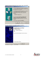
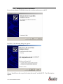
1.2.1 Windows 2000 driver installation
When you turn on the PC, the following dialog box appears.
Click Next. Then, the next dialog box appears.
User’s Manual AR4000 PCI HSIF
3
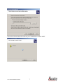
Choose “Search for a suitable driver for my device” and hit NEXT. The following box appears:
Choose “CD-ROM drives” and make sure that the AccuRange PCI High Speed Interface
installation CD-ROM is loaded into the CD-ROM drive prior to hitting NEXT.
The following box appears:
User’s Manual AR4000 PCI HSIF
4
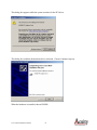
Windows found the appropriate driver on the e: drive. Hit NEXT.
The driver should be successfully installed. Hit YES.
Installation is complete. Hit FINISH.
User’s Manual AR4000 PCI HSIF
5
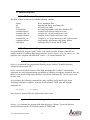
1.2.2 Windows XP driver installation
Be sure the installation CD-ROM is in the drive and turn on the power to the PC
Hit NEXT. The following dialog box appears:
Choose “Install from a list or specific location (Advanced)” and hit NEXT. The following box
appears:
User’s Manual AR4000 PCI HSIF
6
Choose the selection that will read from your CD-ROM drive and hit NEXT.
User’s Manual AR4000 PCI HSIF
7
This dialog box appears while the system searches for the PCI driver.
This dialog box confirms the hardware driver selection. Choose Continue Anyway.
When the hardware is installed, choose FINISH.
User’s Manual AR4000 PCI HSIF
8
1.3 Included Software
1.3.1 CD Directory Tree
The HSIF product includes a CD with the following contents:
\install
\dll
\docs
\examples\bin
\examples\hsiftest
\examples\dist_cap
\examples\distance
\examples\hs_enc
\examples\utilities
\calibration
- driver installation files
- dynamic link library installation files
- API and Users Guide
- precompiled programs, built under Windows XP
- example hsiftest project and source code
- example dist_cap project and source code
- example distance project and source code
- example hs_enc project and source code (with encoder)
- serial interface and dynamic link library utilities
- calibration files for sensor and PCI card
1.3.2 Demonstration Programs
Two demonstration programs with C source code which run under Windows 2000/XP are
supplied with the AccuRange High Speed Interface: hsiftest, distance, dist_cap, and hs_enc. The
programs were compiled with Microsoft Visual C++ 6.0 under Windows XP.
1.6.3.1
Demonstration Program One: hsiftest
hsiftest is a command-line program built from the project “hsiftest” located in directory
\examples\ hsiftest on the CD.
hsiftest exercises all off the features of the High Speed Interface. It takes 2 command line
arguments, the serial communications port number to which the AccuRange is attached, the card
number of the installed High Speed Interface card and the calibration file. See the source code
for more info.
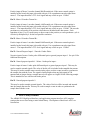
As an example, the following command-line entry would be used to start hsiftest for an
AccuRange attached to comport 1 using the first installed PCI HSIF card and lookuphs
calibration file.
hsiftest 1 1 lookuphs
Once hsiftest is started, follow the instructions on the screen
1.6.3.2
Demonstration Program Two: Distance
distance is a command-line program built from the project “distance” located in directory
\examples\distance on the CD included with the PCI HSIF card.
User’s Manual AR4000 PCI HSIF
9
distance samples data from the High Speed Interface and prints distance in inches, as well as
averaged data obtained from the interface. It takes 5 command line arguments: The serial COM
port number, the installed card number, the sample period in microseconds, the name of the file
containing the calibration data, the number of samples to calibrate and average between printouts
to the screen, and the total number of range captures to print before exiting.
The following command-line demonstrates the program distance for an AccuRange connected to
comport 1 and interface card 1, a sample rate of 10,000 samples/sec (100μs/sample), the
calibration file lookuphs, 10,000 averages per output line, and prints 500 lines of range
capture data before exiting.
distance 1 1 100 lookuphs 10000 500
1.6.3.3
Demonstration Program Three: dist_cap
dist_cap is a command-line program built from the project “dist_cap” located in directory
\examples\dist_cap on the CD.
dist_cap captures unprocessed raw data from the AccuRange sensor and records it to disk.
Afterwards, it processes the raw data and creates several output files which can be loaded into
programs such as Matlab or Excel for analysis. It takes 6 command line arguments: The serial
COM port number, the installed card number, the sample period in microseconds, the name of
the file containing the calibration data, the number of samples to read per call to the driver,
number of calls to the driver, the max range of the sensor (650 inches for full range), and the
capture file base name.
As an example, the following command-line entry would be used to start dist_cap for an
AccuRange attached to comport 1 using the first installed PCI HSIF card and lookuphs
calibration file. This example captures 70,000 continuous samples t a 5us sampling period
(200kHz sampling rate) from the Accurange via 10 calls for 7,000 samples to the driver. The
max range is set to 650 inches.
dist_cap 1 1 5 lookuphs 7000 10 650 my_cap
dist_cap will generate a readable file with processed distances called my_cap.txt.
1.6.3.4
Demonstration Program Four: hs_enc
hs_enc is a command-line program built from the project “hs_enc” located in directory
\examples\hs_enc on the CD.
hs_enc samples data from the High Speed Interface and prints distance in inches, as well as
averaged data obtained from the interface and angular data measured from the scanning encoder.
User’s Manual AR4000 PCI HSIF
10
It takes 5 command line arguments: The serial COM port number, the installed card number, the
sample period in microseconds, the name of the file containing the calibration data, the number
of samples to calibrate and average between printouts to the screen, and the total number of
range captures to print before exiting.
The following command-line demonstrates the program hs_enc for an AccuRange connected to
comport 1 and interface card 1, a sample rate of 10,000 samples/sec (100μs/sample), the
calibration file lookuphs, 10,000 averages per output line, prints 500 lines of range capture
data before exiting, sets the motor power to half voltage (128), sets the number of pulses per
encoder revolution at 8192, and sets the maximum range to 650 inches.
hs_enc 1 1 100 lookuphs 10000 500 128 8192 650
1.4 Sensor Configuration and Sample Rate
When using the High Speed Interface, all configurations of the 4000 are done via the serial port
or push-button interface, just as it would be when using the sensor without the High Speed
Interface. The communication path from the AR4000 to the High Speed Interface is a one-way
data path only; the sensor cannot be configured through the Interface. Since the sample rate of
the Interface is controlled by the rate of the pulse width output of the AR 4000, using the Set
Sample Interval command over the serial port will set the sample rate for the Interface, with one
limitation. The lowest rate at which the internal sampling and therefore the pulse width output of
the sensor can operate is 31 samples per second (32 milliseconds per sample). Setting lower
sample rates will not reduce the pulse width output frequency or the sample rate of the Interface.
To obtain the slowest possible sample rate from the High Speed Interface and the maximum
resolution per sample, use the serial interface to configure the 4000 for a maximum expected
range of 9950 inches, and then set the sample rate. Setting the maximum range to shorter
distances (including the default setting) may cause the pulse width to repeat at higher frequencies
than the sample rate set, depending on the maximum expected range and sample rate specified.
For short maximum range settings, the pulse frequency will be about 5 KHz for sample rates
below that.
The maximum sample rate is 50,000 samples per second (20 microseconds/sample).
1.5 Motor Power
The AR4000 PCI High Speed Interface has two motor power control and encoder reading
channels. Each motor may be set to one of 256 software controlled power levels via commands
to the board. If the motors have encoders which are connected to the encoder inputs, two 8-bit
values from the encoders are decoded and inserted into the data stream, giving the position of
each motor. If the encoders provide index pulses, these can be applied to two of the general
purpose input lines and used to determine the absolute positions of the motors. See the
description of the 25 pin I/O connector for encoder connection details.
User’s Manual AR4000 PCI HSIF
11
If motors are to be driven by the power amplifier on the board, the motors and motor power must
be connected to P2. Motor 1 should be connected between pins 14 and 16, and motor 2 between
pins 1 and 2. A separate power supply is required to drive the motors. Connect the motor power
supply to pin 3 and the power supply ground to pin 15.
1.6 I/O Connectors
There are two connectors on the High Speed Interface. The 9 pin connector (P1) supplies power
and receives signals from the AR4000 sensor. The 25 pin connector (P2) is used for powering
the motors and reading the motor encoders, general purpose inputs, and sample control input.
1.6.1 9 Pin Power and Signal Connector P1
Pin
1
2
3
4
5
6
7
8
9
4000 Wire
Red
Black
Orange
Brown
Yellow
Blue
Green
Purple
Not Used
Function
Power, +5V (5-6V)
Ground
Heater Power, +5V (4.5-7V)
Heater Power Return
Temperature, 0-5 V
Pulse Width Range Signal
Ambient light signal, 0-5 V
Amplitude signal, 0-5 V
Laser Control, 0-5V
Direction
Out
Out
In
In
In
In
Out
P1: Power and Signal Connector Wiring
1.6.2 Power and Signal Connector Description
The line descriptions for P1 are the same as the descriptions of the power and signal lines in the
AR4000 Power and Signal Cable Wire Description section. Pins 1-4 supply sensor power and
sensor heater power and ground lines. The remaining lines are inputs for the signals from the
AR4000 sensor. Pins 5, 7, and 8 are the inputs for the analog signals, with 2K impedance. Pin 6
is the input for the pulse width range signal.
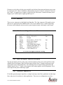
1.6.3 25 Pin I/O Connector P2
P2 includes general purpose input lines, a sample start/stop control line, quadrature encoder input
lines, and power for encoders or other applications. There are two configurations, one for a
User’s Manual AR4000 PCI HSIF
12
single-ended encoder and one for an index pulse, and one for a differential encoder and index
pulse.
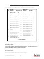
1.6.3.1
P2 Pin Descriptions: Single-Ended Encoder
Below is a table of pin descriptions for a PCI HSIF card with Single-Ended Encoders. See
section 1.4.3.2 for Differential Encoders.
Pin
Top Row
Function
1
Motor 2 Control
Out
2
Motor 2 Return
Out
3
Motor Power Supply
In
4
Ground
5
+5V Power, 100 mA.
6
Ground
7
Ground
8
Ground
9
Ground
10
Ground
11
Ground
Direction
Pin
Bottom Row
Function
14
Motor 1 Control
15
Motor Power Ground
16
Motor 1 Return
Out
17
Laser Control
Out
18
+5V Power, 100 mA
Out
19
Motor 2 Encoder Ch A In
20
Motor 2 Encoder Ch B In
21
Motor 1 Encoder Ch A In
22
Motor 1 Encoder Ch B In
23
Ground
24
General Purpose Input 1 /
Encoder 1 Index Pulse
In
25
General Purpose Input 3 In
Direction
Out
Out
12
Start/Stop Sample Ctrl
In
13
General Purpose Input 2 /
Encoder 2 Index Pulse In
P2: I/O Connector
Pin 1: Motor 2 Control
If used, motor 2 should be connected between this pin and pin 2. The output voltage level is
varied as commanded to control the variable voltage motor.
User’s Manual AR4000 PCI HSIF
13
Pin 2: Motor 2 Return.
If used, motor 2 should be connected between this pin and pin 1.
Pin 3: Motor Power.
The external power supply for the motors should be applied to this line, at +12 to +15 Volts,
depending on the motor used. The line may draw up to 2 amps.
Pin 4: Ground
May be used as ground for encoders or other hardware powered by +5V on pins 5 and 18
Pin 5: +5V power output.
Primarily intended as power for the motor 1 encoder, but it may be used to drive other hardware,
up to 100 mA maximum
Pins 6-10: Ground
May be used as ground for encoders or other hardware powered by +5V on pins 5 and 18
Pin 11: Ground.
May be used as ground for encoders or other hardware powered by +5V on pins 5 and 18
Pin 12: Start/Stop Sample Control Input.
When high, this input enables sampling and samples will be taken until the on-board buffer is
full. When pulled low, sampling will stop. Samples are always completed, so that a full 8 byte
sample is always buffered. This line is pulled up with an on-board 10Kohm resistor, so sampling
is enabled when the input is left open. The first sample following resumption of sampling after
stopping the sampling will not contain valid data, and must be read and discarded.
Pin 13: General purpose input bit 2 / Motor 2 index pulse input.
This may be used to sample external signals. The value of the bit is included in the sampled data
stream. This pin is intended to sample motor encoder index pulses or other events to synchronize
the sample data with the event. The signal is latched high so that any high signal of 100
nanoseconds or longer during a sample interval will appear as a high level following sample.
This is intended for use with encoder index pulses.
Pin 14: Motor 1 Control.
If used, motor 1 should be connected between this pin and pin 14. The output voltage level is
varied as commanded to control the variable voltage motor.
User’s Manual AR4000 PCI HSIF
14
Pin 15: Motor Power Ground.
The external power supply ground for the motors should be connected to this pin.
Pin 16: Motor 1 Ground.
If used, motor 2 should be connected between this pin and pin 16.
Pin 17: Laser Control.
A 0-5V signal used to turn the laser on or off.
Pin 18: +5V power.
Primarily intended as power for the motor 2 encoder, but it may be used to drive other hardware,
up to 100 milliamps maximum
Pin 19: Motor 2 Encoder Channel A.
If the motor control option is installed on the board, this input is decoded with pin 20 as a
quadrature encoder signal from motor 2. The input should be a TTL-level signal and may switch
at up to 1.5 Mhz. The encoder positions are converted to 8 bit position values that ate included
in the data stream. Each transition of pins 19 or 20 causes an up or down count in the position,
so each quadrature cycle is effectively multiplied by 4 for the best possible resolution.
Pin 20: Motor 2 Encoder Channel B.
If the motor control option is installed on the board, this input is decoded with pin 19 as a
quadrature encoder signal from motor 2. The input should be a TTL-level signal and may switch
at up to 1.5 Mhz.
Pin 21: Motor 1 Encoder Channel A.
If the motor control option is installed on the board, this input is decoded with pin 22 as a
quadrature encoder signal from motor 1. The input should be a TTL-level signal and may switch
at up to 1.5 Mhz. The encoder positions are converted to 8 bit position values that are included
in the data stream. Each transition of pins 21 or 22 causes an up or down count in the position,
so each quadrature cycle is effectively multiplied by 4 for the best possible resolution.
Pin 22: Motor 1 Encoder Channel B.
If the motor control option is installed on the board, this input is decoded with pin 21 as a
quadrature encoder signal from motor 1. The input should be a TTL-level signal and may switch
at up to 1.5 Mhz.
Pin 23: Ground
User’s Manual AR4000 PCI HSIF
15
May be used as ground for encoders or other hardware powered by +5V on pins 5 and 18.
Pin 24: General purpose input bit 1 / Motor 1 index pulse input.
This may be used to sample external signals. The value of the bit is included in the sampled data
stream. This pin is intended to sample motor encoder index pulses or other events to synchronize
the sample data with the event. The signal is latched high so that any high signal of 100
nanoseconds or longer during a sample interval will appear as a high level following sample.
This is intended for use with encoder index pulses.
Pin 25: General purpose input bit 3.
This may be used to sample external signals. The value of the bit will be inverted and inserted
into the sample data stream. This may be used to sample events in order to synchronize the
sample data with the event.
User’s Manual AR4000 PCI HSIF
16
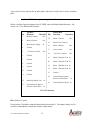
1.6.3.2
P2 Pin Descriptions: Differential Encoders
Below is a table of pin descriptions for a PCI HSIF card with Differential Encoders:
Pin
Top Row
Function
1
Motor 2 Control
Out
2
Motor 2 Return
Out
3
Motor Power Supply
In
4
Ground
5
+5V Power, 100 mA.
6
Motor 2 Encoder Ch A- In
7
Motor 2 Encoder Ch B- In
8
Motor 1 Encoder Ch A- In
9
Motor 1 Encoder Ch B- In
10
Ground
11
12
13
Direction
Pin
Bottom Row
Function
14
Motor 1 Control
15
Motor Power Ground
16
Motor 1 Return
Out
17
Laser Control
Out
18
+5V Power, 100 mA
Out
19
Motor 2 Encoder Ch A+ In
20
Motor 2 Encoder Ch B+ In
21
Motor 1 Encoder Ch A+ In
22
Motor 1 Encoder Ch B+ In
23
General Purpose Input 1/ In
Encoder 1 Index Pulse-
24
General Purpose Input 1 /
Encoder 1 Index Pulse+ In
25
General Purpose Input 3
Direction
Out
Out
General Purpose Input 2/ In
Encoder 2 Index PulseStart/Stop Sample Ctrl, In
In
General Purpose Input 2 /
Encoder 2 Index Pulse+ In
P2: I/O Connector
Pin 1: Motor 2 Control
If used, motor 2 should be connected between this pin and pin 2. The output voltage level is
varied as commanded to control the variable voltage motor.
Pin 2: Motor 2 Return.
If used, motor 2 should be connected between this pin and pin 1.
User’s Manual AR4000 PCI HSIF
17
Pin 3: Motor Power.
The external power supply for the motors should be applied to this line, at +12 to +15 Volts,
depending on the motor used. The line may draw up to 2 amps.
Pin 4: Ground
May be used as ground for encoders or other hardware powered by +5V on pins 5 and 18.
Pin 5: +5V power output.
Primarily intended as power for the motor 1 encoder, but it may be used to drive other hardware,
up to 100 mA maximum.
Pin 6: Motor 2 Encoder Ch ANegative input of motor 2 encoder channel A differential pair. See pin 19 for functional
description.
Pin 7: Motor 2 Encoder Ch BNegative input of motor 2 encoder channel B differential pair. See pin 20 for functional
description.
Pin 8: Motor 1 Encoder Ch ANegative input of motor 1 encoder channel A differential pair. See pin 21 for functional
description.
Pin 9: Motor 1 Encoder Ch BNegative input of motor 1 encoder channel B differential pair. See pin 22 for functional
description.
Pin 11: General Purpose Input 2 / Encoder 2 Index PulseNegative input of motor 2 index pulse differential pair or general purpose input 2. See pin 13 for
functional description.
Pin 12: Start/Stop Sample Control Input.
When high, this input enables sampling and samples will be taken until the on-board buffer is
full. When pulled low, sampling will stop. Samples are always completed, so that a full 8 byte
sample is always buffered. This line is pulled up with an on-board 10Kohm resistor, so sampling
User’s Manual AR4000 PCI HSIF
18
is enabled when the input is left open. The first sample following resumption of sampling after
stopping the sampling will not contain valid data, and must be read and discarded.
Pin 13: General purpose input bit 2 / Motor 2 index pulse input+.
Positive input of motor 2 index pulse differential pair or general purpose input 2. This may be
used to sample external signals. The value of the bit will is included in the sampled data stream.
This may be used to sample motor encoder index pulses or other events in order to synchronize
the sample data with the event. The signal is latched high so that any high signal of 100
nanoseconds or longer during a sample interval will appear as a high level the following sample.
This is intended for use with encoder index pulses.
Pin 14: Motor 1 Control.
If used, motor 1 should be connected between this pin and pin 14. The output voltage level is
varied as commanded to control the variable voltage motor.
Pin 15: Motor Power Ground.
The external power supply ground for the motors should be connected to this pin.
Pin 16: Motor 1 Ground.
If used, motor 2 should be connected between this pin and pin 16.
Pin 17: Laser Control.
A 0-5V signal used to turn the laser on or off.
Pin 18: +5V power.
Primarily intended as power for the motor 2 encoder, but it may be used to drive other hardware,
up to 100 milliamps maximum.
Pin 19: Motor 2 Encoder Channel A+
Positive input of motor 2 encoder channel A differential pair. If the motor control option is
installed on the board, this input is decoded with pin 20 as a quadrature encoder signal from
motor 2. The input should be a TTL-level signal and may switch at up to 1.5 Mhz. The encoder
positions are converted to 8 bit position values that ate included in the data stream. Each
transition of pins 19 or 20 causes an up or down count in the position, so each quadrature cycle is
effectively multiplied by 4 for the best possible resolution.
Pin 20: Motor 2 Encoder Channel B+.
User’s Manual AR4000 PCI HSIF
19
Positive input of Motor 2 encoder channel B differential pair. If the motor control option is
installed on the board, this input is decoded with pin 19 as a quadrature encoder signal from
motor 2. The input should be a TTL-level signal and may switch at up to 1.5 Mhz.
Pin 21: Motor 1 Encoder Channel A+.
Positive input of motor 1 encoder channel A differential pair. If the motor control option is
installed on the board, this input is decoded with pin 22 as a quadrature encoder signal from
motor 1. The input should be a TTL-level signal and may switch at up to 1.5 Mhz. The encoder
positions are converted to 8 bit position values that are included in the data stream. Each
transition of pins 21 or 22 causes an up or down count in the position, so each quadrature cycle is
effectively multiplied by 4 for the best possible resolution.
Pin 22: Motor 1 Encoder Channel B+.
Positive input of motor 1 encoder channel B differential pair. If the motor control option is
installed on the board, this input is decoded with pin 21 as a quadrature encoder signal from
motor 1. The input should be a TTL-level signal and may switch at up to 1.5 Mhz.
Pin 23: General Purpose Input 1 / Encoder 1 Index PulseNegative input of motor 1 index pulse differential pair or general purpose input 1. See pin 24 for
functional description.
Pin 24: General purpose input bit 1 / Motor 1 index pulse input+.
Positive input of motor 1 index pulse differential pair or general purpose input 1. This may be
used to sample external signals. The value of the bit will is included in the sampled data stream.
This may be used to sample motor encoder index pulses or other events in order to synchronize
the sample data with the event. The signal is latched high so that any high signal of 100
nanoseconds or longer during a sample interval will appear as a high level the following sample.
This is intended for use with encoder index pulses.
Pin 25: General purpose input bit 3.
This may be used to sample external signals. The value of the bit will be inverted and inserted
into the sample data stream. This may be used to sample events in order to synchronize the
sample data with the event.
1.7 HSIF Library Routines
The AR4000 PCI High Speed Interface card application program interface (API) employs
routines that are accessed using a static linked library. Descriptions of those basic API’s are
listed below
User’s Manual AR4000 PCI HSIF
20
1.7.1 Initialize the library
Initialize the library before using any of its functions.
BOOL HsifDllInit()
Returns:
TRUE
FALSE
library initialization successful
library failed to initialize
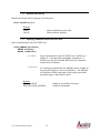
1.7.2 Opening communications with the card
Open communication with a PCI HSIF card.
HSIF_HANDLE HsifOpen(
DWORD hsifNum,
DWORD comHandle)
hsifNum
Open communication with a PCI HSIF card. hsifNum is a
number 0 – 4, denoting the card number assignment. If
hsifNum is 0, the first available HSIF device is returned as
enumerated by Windows.
comHandle
If a serial port is dedicated to the AR4000 sensor, a handle to
the opened COM device can be included here. The AR4000
will enable the PWM output and set the sample period and
maximum range to their default values.
Returns:
HSIF_HANDLE
HSIF_INVALID_HANDLE
User’s Manual AR4000 PCI HSIF
handle (0-4) to hsifCard resource
invalid or null handle
21
1.7.3 Closing access to the card
Close the application’s access to the PCI HSIF card. Calling the card with an invalid handle is
not destructive.
HSIF_RESULT HsifClose(
HSIF_HANDLE hsifCard)
Returns:
HSIF_SUCCESS
HSIF_FAIL
the HSIF card closed successfully and the
resources are freed.
the HSIF card failed to close (because the
specified card was not open)
1.7.4 Sampling mode initialization
Set HSIF card to sampling mode. This must be done before the card will capture samples.
HSIF_RESULT HsifSamplingModeInit(
HSIF_HANDLE hsifCard)
Returns:
HSIF_SUCCESS
HSIF_FAIL
sampling mode entered successfully
unable to enter sampling mode
1.7.5 Reset PCI HSIF card
Performs a hardware reset of the PCI HSIF card. After this, all initialization must be performed
again.
HSIF_RESULT HsifResetBoard(
HSIF_HANDLE hsifCard)
Returns:
HSIF_SUCCESS
HSIF_FAIL
User’s Manual AR4000 PCI HSIF
the HSIF card was successfully reset
the HSIF card reset failed
22
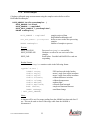
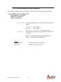
1.7.6 Get Buffered Samples
This function gets up to numSamples samples from the HSIF card or waits until
numSamples have been received if wait is set to TRUE. The number of samples read is
returned in numRead.
HSIF_RESULT HsifGetBufferedSamples (
HSIF_HANDLE hsifCard,
HSIF_SAMPLE * sampleBuf,
DWORD numSamples,
DWORD *numRead,
BOOL wait)
sampleBuf
numSamples
numRead
wait
Storage buffer for the retrieved samples
The number of samples to read from the card
The actual number of samples read.
When TRUE, the function will block until numSamples
have been read from the card.
When FALSE, the function will return immediately with 0
to numSamples in the sampleBuf as indicated by
numRead
Returns:
HSIF_SUCCESS
HSIF_FAIL
Read up to numSamples successfully
Read failure. Possible bad HANDLE or card not esponding
Sample Contents:
HSIF_SAMPLE contains the following data in the specified format:
typedef struct {
DWORD status;
DWORD encoder1;
DWORD encoder2;
DWORD range;
} HSIF_SAMPLE;
User’s Manual AR4000 PCI HSIF
23
index latches, temp, ambient,
amplitude, and other status info
motor 1 position
motor 2 position
uncalibrated range measurement
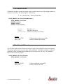
1.7.7 Set sample period and maximum range
Set the sample period and maximum range for the card. Once this data is set, it is used internally
by HsifProcessSamples
HSIF_RESULT HsifSetSamplePeriod(
HSIF_HANDLE hsifCard,
HANDLE comHandle,
DWORD range,
DWORD samplePeriod)
hsifCard
The HSIF card’s number from the above function
comHandle
Handle to a comport
range
Max measurement range, default is 650 inches.
samplePeriod Period between samples in microseconds.
Returns:
HSIF_SUCCESS
Read up to numSamples successfully
HSIF_WARN_COM Sample period updated internally, but an invalid com
handle was specified and thus no serial communication
with the AR4000 was attempted.
HSIF_FAIL
Read failure. Possible bad HANDLE or card not esponding
User’s Manual AR4000 PCI HSIF
24
1.7.8 Process samples
Calculates calibrated range measurements using the samples retrieved after a call to
HsifGetBufferedSamples
HSIF_RESULT HsifProcessSamples (
HSIF_HANDLE hsifCard,
HSIF_SAMPLE * sampleBuf,
HSIF_PROC_SAMPLE * procSampleBuf,
DWORD numSamples)
HSIF_SAMPLE * sampleBuf
HSIF_PROC_SAMPLE * procSampleBuf
DWORD numSamples
Returns:
HSIF_SUCCESS
HSIF_OVERFLOW
HSIF_FAIL
samples retrieved from
HsifGetBufferedSamples call
buffer to store results after processing
samples
Number of samples to process
Processed numSamples successfully
Hardware overflow bit was set in one of the
samples
Read failure. Possible bad HANDLE or card not
responding
Results Format:
HsifProcessSamples contains results in the following format
typedef struct {
USHORT status;
double angle1;
double angle2;
double distance;
double caltemp;
double ambient;
double amplitude;
BOOL timeout;
DWORD rawRange;
} HSIF_PROC_SAMPLE;
FIFO and encoder index latches.
motor 1 angle from offset in radians
motor 2 angle from offset in radians
calibrated distance in inches
calibrated temperature
ambient light
reflected signal strength
sample measurement timeout
uncalibrated range
Notes:
A timeout will be set if no range reading from the AR4000 was detected after 13
ms. This can be used to detect if the range cable from the AR4000 is
disconnected.
User’s Manual AR4000 PCI HSIF
25
1.7.9 Load calibration file
Load calibration file for the sensor/card pair. This file is shipped with each AR4000 and PCI
HSIF card set. The calibration file is used by ProcessSamples for generating true distance
measurements.
BOOL HsifLoadCalibrationData (
HSIF_HANDLE hsifCard,
LPCSTR filename)
filename
name location for calibration file
Returns:
HSIF_SUCCESS
HSIF_FAIL
Read successfully
File not found or File corrupted
1.7.10 Laser on
Enable the laser.
HSIF_RESULT HsifLaserOn(
HSIF_HANDLE hsifCard)
Returns:
HSIF_SUCCESS
HSIF_FAIL
Laser on output successfully set
Laser on output set failed.
Note:
The current AR4000 sensors do not read this output from the PCI HSIF card. To
turn the laser on, use the serial command “H”.
User’s Manual AR4000 PCI HSIF
26
1.7.11 Laser off
Disable the laser.
HSIF_RESULT HsifLaserOff(
HSIF_HANDLE hsifCard)
Returns:
HSIF_SUCCESS
HSIF_FAIL
Laser on output successfully set
Laser on output set failed.
Note:
The current AR4000 sensors do not read this output from the PCI HSIF card. To
turn the laser off, use the serial command “L”.
1.7.12 Sampling enable
Enable sampling of range data from the AR4000 sensor. This function must be called after
HsifClearSampleBuffer, since that function automatically disables sampling after clearing the
sample buffers.
HSIF_RESULT HsifSamplingEnable(
HSIF_HANDLE hsifCard)
Returns:
HSIF_SUCCESS
HSIF_FAIL
Sampling enabled successfully
Sampling enable failed.
1.7.13 Sampling Disable
Disable sampling of range data from the AR4000 sensor.
HSIF_RESULT HsifSamplingDisable(
HSIF_HANDLE hsifCard)
Returns:
HSIF_SUCCESS
HSIF_FAIL
User’s Manual AR4000 PCI HSIF
Sampling disabled successfully
Sampling disable failed
27
1.7.14 Clear overflow
Clear the hardware and software buffer overflow flags.
HSIF_RESULT HsifClearOverflow(
HSIF_HANDLE hsifCard)
Returns:
HSIF_SUCCESS
HSIF_FAIL
Overflow cleared successfully
Overflow clear failed
1.7.15 Clear sample buffer
Clear all samples that have been buffered into hardware and software.
HSIF_RESULT HsifClearSampleBuffer(
HSIF_HANDLE hsifCard)
Returns:
HSIF_SUCCESS
HSIF_FAIL
Samples cleared successfully.
Sample clear failed
1.7.16 Get number of samples available in buffer
Return the number of samples available to be read.
HSIF_RESULT HsifDataAvailable(
HSIF_HANDLE hsifCard,
DWORD * numSamplesAvailable)
numSamplesAvailable The number of samples available is returned
through this pointer.
Returns:
HSIF_SUCCESS
HSIF_FAIL
User’s Manual AR4000 PCI HSIF
Accessed number of samples available successfully.
Could not access number of samples available.
28
1.7.17 Get overflow status
Return the software and hardware overflow status. If the overflow status is TRUE, the
application isn’t reading samples out of the buffer fast enough.
HSIF_RESULT HsifGetOverflowStatus(
HSIF_HANDLE hsifCard,
BOOL * overflowStatus)
overflowStatus Logical and of the hardware and software overflow
status.
Returns:
HSIF_SUCCESS
HSIF_FAIL
Returned the overflow status successfully.
Failed to return the overflow status.
1.7.18 Set motor power
Set power for motors 1 and 2. The powers may be set from 0 to 255, corresponding to zero
power to full power.
HSIF_RESULT HsifSetMotorPower(
HSIF_HANDLE hsifCard,
DWORD motorNum,
DWORD power)
motorNum
power
Returns:
HSIF_SUCCESS
HSIF_FAIL
User’s Manual AR4000 PCI HSIF
1 or 2 are valid motor numbers.
0 (off) to 255 (full power)
Set the motor power successfully.
Failed to set the motor power.
29
1.7.19 Clear motor position encoder accumulator
Clear either one or both encoders immediately or the next time the index pulse comes around.
HSIF_RESULT HsifClearEncoder(
HSIF_HANDLE hsifCard,
DWORD encoderMask,
BOOL withIndex)
encoderMask Set to the following value to select which encoder will be
cleared:
withIndex
ENCODER1 – clear encoder 1
ENCODER2 – clear encoder 2
ENCODER1 | ENCODER2 – clear both encoders
Set to the following value to select when the encoder will
be cleared:
TRUE – clear the encoder when the index pulse is set
FALSE – clear the encoder immediately
Returns:
HSIF_SUCCESS
HSIF_FAIL
User’s Manual AR4000 PCI HSIF
Set the motor power successfully.
Failed to set the motor power.
30
1.7.20 Calibrate encoder
Calibrate the encoders to return the proper angle in radians based on an offset and the number of
counts per revolution. The motor angle is calculated as:
2 * π * (encoderCount – offset)/countsPerRev
HSIF_RESULT HsifCalibrateEncoder(
HSIF_HANDLE hsifCard,
DWORD encoder,
DWORD offset,
DWORD countsPerRev)
encoder
Encoder 1 or 2
offset
Encoder count offset
countsPerRev Number of counts per revolution
Returns:
HSIF_SUCCESS
HSIF_FAIL
Calibrated the encoders successfully
Failed to calibrate the encoders.
1.7.21 Calibrate HSIF card
The PCI HSIF card must be calibrated to ensure accurate range readings in a given enviornment.
This must be performed at least once after calling HsifOpen. Calibrations should be performed
periodically if the environmental conditions the card is exposed to will vary. The procedure
takes several seconds to perform.
HSIF_RESULT HsifCalibrate(
HSIF_HANDLE hsifCard)
Returns:
HSIF_SUCCESS
HSIF_FAIL
User’s Manual AR4000 PCI HSIF
Card was calibrated successfully
Failed to calibrate the card
31
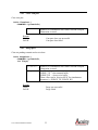
1.7.22 Set poll mode
Enable polling mode when the sample period is large. If this is set to FALSE, there will be a
latency of 2048 samples between transfers from the HSIF card buffer to PC’s local memory.
HSIF_RESULT HsifSetPollMode(
HSIF_HANDLE hsifCard,
BOOL mode)
Returns:
HSIF_SUCCESS
HSIF_FAIL
Poll mode was successfully set.
Failed setting poll mode
1.8 Serial I/O Utilities
The Serial I/O Utilities comprise a set of functions for accessing the AR-4000 sensor through the
serial port. These functions are used internally by the HSIF Library for setting the resolution and
range of the AR-4000 sensor if the address of an open COMMINFO struct is passed to the
HsifOpen routine when opening access to the card, or during a call to HsifSetSamplePeriod.
1.8.1 Open a com port to communicate with an AR-4000 sensor
Open a com port at the baud rate specified.
BOOL OpenPort(
COMMINFO *pCommInfo,
int baudrate,
int Portnum)
pCommInfo
baudrate
Portnum
Returns:
TRUE
FALSE
User’s Manual AR4000 PCI HSIF
pointer to a COMMINFO struct where relevant com port
information is stored
baud rate the sensor is configured for. Normally this is
9600.
com port number to open
Com port was successfully opened
Com port open failed.
32
1.8.2 Close com port
Close com port.
BOOL ClosePort(
COMMINFO *pCommInfo)
pCommInfo
pointer to a COMMINFO struct where relevant com port
information is stored.
Returns:
TRUE
FALSE
Com port close was successful
Com port close failed
1.8.3 Purge port
Clear out pending transmit and receive data
BOOL PurgePort(
COMMINFO *pCommInfo,
int flags)
pCommInfo
flags
Returns:
TRUE
FALSE
User’s Manual AR4000 PCI HSIF
pointer to a COMMINFO struct where relevant com port
information is stored.
Possible settings:
PURGE_TX - clear transmit buffer
PURGE_RX - clear receive buffer
These values can be “bitwise OR’d” for simultaneous
operation, i.e. PURGE_TX | PURGE_RX
Purge was successful
Purge failed
33
1.8.4 Send serial data to the AR-4000 sensor
Send a string of characters to the AR-4000 sensor.
BOOL sendstr(
COMMINFO *pCommInfo,
char str[])
pCommInfo
str
Returns:
TRUE
FALSE
pointer to a COMMINFO struct where relevant com port
information is stored.
null-terminated string of characters to transmit to the AR4000 sensor
String was transmitted successfully
String transmit failed.
1.8.5 Read a line of characters from the AR-4000 sensor
Read a line of characters from the AR-4000 sensor when in ASCII output mode.
unsigned int ascii_read_line(
COMMINFO *pCommInfo,
char *buf,
unsigned int nMaxLength,
BOOL crlf,
int timeout)
pointer to a COMMINFO struct where relevant com port
information is stored.
buf
storage space for characters read from the AR-4000 sensor
nMaxLength maximum number of characters that can be put in the buf
storage space
crlf
TRUE - read a carriage return/line-feed pair as the end of
line indicator.
FALSE – read a line-feed as the end of line indicator.
This should be set to TRUE for AR-4000 sensor.
timeout
Number of milliseconds to wait before returning from the
call if no data is detected.
pCommInfo
Returns:
number of bytes read
ASCII_TIMEOUT
User’s Manual AR4000 PCI HSIF
If read was successful.
If read times out.
34
1.8.6 Read binary data bytes from the AR-4000 sensor
Read a specified number of bytes from the AR-4000 sensor when in binary mode.
unsigned int ascii_read_line(
COMMINFO *pCommInfo,
char *buf,
unsigned int nMaxLength,
int timeout)
pointer to a COMMINFO struct where relevant com port
information is stored.
buf
storage space for characters read from the AR-4000 sensor
nMaxLength maximum number of characters that can be put in the buf
storage space
timeout
Number of milliseconds to wait before returning from the
call if no data is detected.
pCommInfo
Returns:
number of bytes read
BINARY_TIMEOUT
If read was successful.
If read times out.
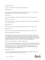
1.9 Sampled Data Format
The interface board collects 16 bytes/sample in a sequential stream which are read as samples
with function HsifGetBufferedSamples. If memory buffer overflow occurs, the board
will always drop complete samples, so that synchronization is not lost. If a software board reset
command is issued, the next byte read will be the first byte of a complete sample, and unread and
partially read samples will be lost.
In general the values for amplitude and ambient light level, will correspond closely to the values
from the 4000’s serial interface, with the ASCII format serial data being 4 times the High Speed
Interface values for amplitude and ambient light. However, the values will not match exactly,
and the calibration software supplied for use with the High Speed Interface must be used with the
values obtained from the HSIF, not serial data. The temperature and range have different scale
factors from the serial data and must be scaled using algorithms found in the software supplied
with the interface. Below is a table that details the sample data format:
User’s Manual AR4000 PCI HSIF
35
DWord #
0
1
2
3
Bit #
0
1
2
3
7-4
15-8
23-16
31-24
31-0
31-0
31-0
Contents
Hardware Buffer Overflow Indicator
Input 3
Motor 1 Encoder Index / Input 1
Motor 2 Encoder Index / Input 2
Sample Count 0-15
8-bit Sensor Internal Temperature
8-bit Ambient Light Sample
8-bit Amplitude Sample
32-bit Motor 1 Encoder Position
32-bit Motor 2 Encoder Position
32-bit Range
Sampled Data Format
1.9.1 Description of Sampled Data Format
Amplitude: 8-bit sample of the AR4000 logarithmic signal strength output. The sample
represents the amplitude of the modulated signal sensed by the detector. The amplitude sample
is taken in the first 10 microseconds of the data sample interval.
Ambient Light: 8-bit sample of the AR4000 ambient light output. The sample represents the
ambient or background light sensed by the detector. It will also register the light transmitted by
the sensor, so changing range signal strengths will affect this reading somewhat. The ambient
light sample is taken in the first 10 microseconds of the data sample interval.
Internal temperature: 8-bit sample of the AR4000 internal temperature. The temperature is
sampled in the first 10 microseconds of the data sample interval.
Range: 32-bit value which must be processed through HsifProcessSamples to get a rawRange
value that will be proportional to the distance to the object being ranged, within the uncalibrated
linearity of the AR4000.
Buffer overflow indicator: 1 bit indicating whether a memory buffer overflow occurred and 1
or more samples were lost just prior to the first sample in which the flag is set. Once an
overflow occurs, this bit will stay set until a HsifClearOverflow or Reset Interface Board
command is given or a power cycle occurs. Samples with the overflow flag set may contain
inaccurate range data and should be discarded. Since the overflow flag is stored with the buffered
data, resetting the flag will not become evident in the data until the data in the buffer has been
read, or the buffer has been cleared with a board reset command. Note that if the buffer is full
when the HsifClearOverflow command is given, it will simply be set again immediately.
User’s Manual AR4000 PCI HSIF
36
Inputs 1, 2, 3: 3 general purpose input lines, CMOS logic levels. These may be used to
determine the exact times of external events relative to the samples taken.
Inputs 1 and 2 are set on the positive rising edge of signals input to these pins. After the next
sample is written, the inputs are automatically cleared. Input 3 is a general purpose, level-sensed
input.
Motor 1, 2 Encoder Index: Indicates when a motor has completed a revolution. When Inputs 1
and 2 are used to indicate motor encoder index they will be unavailable for use as general
purpose inputs.
Motor 1 Encoder Position: 32-bit sample of the position of motor encoder 1, if the motor
control option is installed and a motor encoder is attached to the P2 motor 1 encoder inputs. The
position will wrap to 0 after reaching ~ 4.3 billion.
Motor 2 Encoder Position: 32-bit sample of the position of motor encoder 2, if the motor
control option is installed and a motor encoder is attached to the P2 motor 2 encoder inputs. The
position will wrap to 0 after reaching ~ 4.3 billion.
1.10 Interface Installation and Checkout
To install the AR4000 PCI High Speed Interface board, first install the computer drivers from the
supplied CD according to the directions in section 1.2. When complete, physically install the
PCI board into an available PCI slot in your computer. Attach the AR4000 Power and Signal
cable to the 9 pin connector (P1). Turn on the computer power. Check out the operation of the
AR4000 as described in the Initial Checkout section.
1.10.1 Diagnostics
Install the PCI High Speed Interface in a bus slot, connect the sensor to the HSIF board and to a
serial port on the computer. Be sure that power is being supplied to the AR4000 sensor.
If the sensor’s LED does not come on, check the connection of the sensor to the interface. The
serial connection to the sensor may be tested separately using a program such as the Windows
terminal to observe sensor output and send commands. If the sensor does not respond to serial
communications, check the serial port connection.
After installing the board and connecting the AR4000 sensor, run the demo/diagnostic software
supplied with the board, following the instructions at the beginning of this manual.
If the motor control option is not installed, the encoder tests will not succeed. If you have not
connected the input lines and external sample control line to 0/5 volt signals, the tests of those
lines will not succeed. All other tests should succeed.
User’s Manual AR4000 PCI HSIF
37
If the one or more of the Interface tests fail, check the port address you give the diagnostic software. Also
make sure that no other boards in the computer system are using the address group. Verify that the serial
port the sensor is connected to is the port number you give the diagnostic software. Check that the
sensor’s serial port is configured for 9600 baud.
If the sensor stability tests fail, check that the laser comes on during those tests and that the sensor is
pointed a white target 1 to 2 yards from the sensor.
User’s Manual AR4000 PCI HSIF
38