1
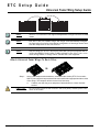
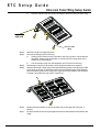
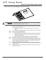
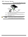
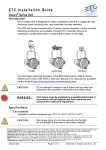
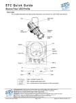
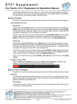
ETC® Setup Guide Universal Fader Wing Installation I n tr o d u c ti o n The Universal Fader Wings are peripheral devices that can expand the functionality of your ETC Eos®, Eos Ti™, Gio™, Ion®, Cobalt®, Congo®, or Congo jr™ lighting control system. Fader wings are available in two different sizes: 2 x 10 (20 faders) and 2 x 20 (40 faders). Fader wings can be physically attached to a console or they can stand alone and attach using a USB cable and an external power supply. For information about the 1x20 fader wing, please see the Universal Fader Wing - 1x20 Setup Guide, which is available for download from the ETC website at www.etcconnect.com. Note: The 2 x 10 and 2 x 20 Universal Fader Wings are compatible with Eos v1.3.1 or higher (running on Eos, Eos Ti, Gio, Ion, Net3 RVI, Eos RPU, or Nomad/Eos Family Client or Offline Software in Eos, Gio, or Ion Mode, running on a PC. The Mac OS is not supported). Fader Wings are supported on Cobalt, Congo, and Congo jr consoles with version 6.x.x software and above. The software is available from the ETC website at www.etcconnect.com. Consult the user manual and/or release notes of those control systems to determine the level of compatibility and complete functionality of the wings within those systems. Rules of Connection . CAUTION: Disconnect power from your console before connecting or removing fader wings. “Hot swapping” (connecting or disconnecting with a powered, running console) is not advised and may cause data loss or other unexpected results. Universal Fader Wings may be connected together and then connected to Eos, Eos Ti, Gio, Ion, Cobalt, Congo, or Congo jr consoles using a USB cable. They may also be physically attached to both Ion and Congo jr consoles. When attaching fader wings with a USB cable, one external power supply must also be used. Ru le One for USB 1.1 Co nsoles Eos/Ion: Your entire system is limited to a total of 300 faders per processor (Eos, Eos Ti, Gio, Ion, RPU, RVI). Note: Element™ does not support external fader wings. Cobalt/Congo/Congo jr: Cobalt and Congo consoles support up to 80 Master Playback faders, 40 of which are built into the console itself. Congo can support the connection of additional faders (up to two 2x10, or 1 2x20 wing, or the Master Playback Wing) via USB cable. The wing requires an external power supply when used via USB cable. Congo jr consoles can support up to a total of 80 Master Playback faders (console + wings), in any combination of wings, as long as the total fader count is 80 or fewer. Note: Congo Kid™ does not support external wings. Corporate Headquarters 3031 Pleasant View Road, P.O. Box 620979, Middleton, Wisconsin 53562-0979 USA Tel +608 831 4116 Fax +608 836 1736 London, UK Unit 26-28, Victoria Industrial Estate, Victoria Road, London W3 6UU, UK Tel +44 (0)20 8896 1000 Fax +44 (0)20 8896 2000 Rome, IT Via Pieve Torina, 48, 00156 Rome, Italy Tel +39 (06) 32 111 683 Fax +44 (0) 20 8752 8486 Holzkirchen, DE Ohmstrasse 3, 83607 Holzkirchen, Germany Tel +49 (80 24) 47 00-0 Fax +49 (80 24) 47 00-3 00 Hong Kong Room 1801, 18/F, Tower 1 Phase 1, Enterprise Square, 9 Sheung Yuet Road, Kowloon Bay, Kowloon, Hong Kong Tel +852 2799 1220 Fax +852 2799 9325 Service: (Americas) [email protected] (UK) [email protected] (DE) [email protected] (Asia) [email protected] Web: www.etcconnect.com Copyright © 2014 ETC. All Rights Reserved. Product information and specifications subject to change. 4310M2110 Rev E Released 2014-04 ETC intends this document to be provided in its entirety. Uni ver s al F ad er Wi ng Set u p Gui de Pag e 1 of 6 El ect r on ic T he at r e Con t ro ls , I nc . ETC Setup Guide Universal Fader Wing Setup Guide Ru le One for USB 2.0 Co nsoles G io : Your entire system is limited to a total of 300 faders per processor (Eos, Eos Ti, Gio, Ion, RPU, RVI). Each fader wing can connect directly to an USB port on Gio, but must be powered separately. Fader wings can be daisy chained together, but they must be plugged into a USB 1.1 hub and then connected to an USB port on Gio. There is a limit of three wings per port. Rule Two No more than three fader wings may be physically attached to each other. This means: • A maximum of three fader wings may be directly attached to either side of a console. For example: • A maximum of three fader wings may be connected using a USB cable to form a single external array using an external power supply. For example: U ni ver sa l F ad er Win g S et u p G ui de Page 2 of 6 El ect r on ic T he at r e C on tr o ls , I nc. ETC Setup Guide Universal Fader Wing Setup Guide Note: Since v1.7.0, Eos and Ion can support multiple banks of wings connected via USB cables. Note: Eos, Eos Ti, Gio, Ion, Cobalt, Congo, and Congo Jr will automatically configure the fader wings from left to right. Manual configuration of the wings can be done from the Setup menu of Eos, Gio, and Ion. Note: Only one wing (2 x 10 or 2 x 20) may be used with a personal computer that is running Nomad/Eos Family Client or Offline software in Eos, Eos Ti, Gio, or Ion mode, Congo Offline, or Congo Client. The Mac OS is not supported. A t t a c h U n i v e r s a l F a d e r Wi n g s To E a c h O t h e r OR Step 1: Using a #1 Phillips head screwdriver, remove the two screws (ETC Part number HW117) securing the bumpers that will be removed from the appropriate side or sides of the wings. The bumpers will be removed in a later step. a: Carefully turn the wing over and place it faders-down on a clear, flat work surface. CAUTION: U ni ver sa l F ad er Win g S et u p G ui de Do not set the console on the connector side (rear panel). Instead, place it face down on the faders. Page 3 of 6 El ect r on ic T he at r e C on tr o ls , I nc. ETC Setup Guide Universal Fader Wing Setup Guide b: Remove and save the two screws securing the bumper to the side of the wing. 3 bumpers on either side 1 2 1 Step 2: Step 3: Step 4: Step 5: Step 6: Step 7: ETC Part number HW117 Return the wing to its upright position. Remove the bumper(s) from the wing. a: Gently pull the bumper on the right side of the wing up until it is flush with the facepanel. Gently push the bumper on the left side of the wing down until it loosens from the facepanel. b: Pull the bumper away from the facepanel until it is free from the wing. Repeat steps 2 and 3 for each side of each wing that needs to be exposed. Align the two wings. Lift the wing on the right and place it gently on the hooks provided on the wing on the left. Check that the two wings are aligned properly front and back, then press down gently on the wing on the right until it is fully seated. This should be a smooth connection but may require a little force. Repeat above procedure to connect another wing to the right end of the pair, if desired. Re-insert screws to secure wings together and secure the bumpers to the sides of the wings. U ni ver sa l F ad er Win g S et u p G ui de Page 4 of 6 El ect r on ic T he at r e C on tr o ls , I nc. ETC Setup Guide Universal Fader Wing Setup Guide A t t a c h U n i v e r s a l F a d e r Wi n g ( s ) d i r e c t l y t o C o n s o l e r oj ong C r o Ion onsole C CAUTION: Step 1: Step 2: Step 3: Step 4: Step 5: Step 6: Step 7: No USB cables or external power supplies should be used when connecting Universal Fader Wings directly to a console. Using a #1 Phillips head screwdriver, remove the two screws securing the bumpers that will be removed from the appropriate side or sides of the wings. The bumpers will be removed in a later step. a: Carefully turn the wing over and place it faders-down on a clear, flat work surface. b: Remove and save the two screws securing the bumper to the side of the wing. Return the wing to its upright position. Remove the bumper(s) from the wing. a: Gently pull the bumper on the right side of the wing up until it is flush with the facepanel. Gently push the bumper on the left side of the wing down until it loosens from the facepanel. b: Pull the bumper away from the facepanel until it is free from the wing. Repeat steps 2 and 3 for each side of each wing that needs to be exposed. Align the wing and the console. Lift the wing and place it gently on the hooks provided on the console. Check that the wing and the console are aligned properly front and back, then press down gently on the wing until it is fully seated. This should be a smooth connection but may require a little force. Repeat above procedure to connect another wing to the other side of the console, if desired. If multiple wings are to be used, attach them to one another first and then to the console itself. Re-insert screws to secure wings and console together and secure the bumpers to the sides of the wings. U ni ver sa l F ad er Win g S et u p G ui de Page 5 of 6 El ect r on ic T he at r e C on tr o ls , I nc. ETC Setup Guide Universal Fader Wing Setup Guide C o n n e c t U n i v e r s a l F a d e r Wi n g ( s) t o C o n s o l e w i t h U S B C a b l e connect PS372 12VDC power supply cable (included) connect to USB on the console connect USB cable (included) Step 1: Step 2: Step 3: Step 4: With the console power off, attach the USB cable (provided) between the console and one wing as shown above. If multiple wings are joined, only one power and one USB connection may be used for all joined wings. Using the power supply adaptor kit, connect the fader wing to a power source. It is recommended that you run the power and USB cables through the strain relief included on the back of the wings. Turn the console on. CAUTION: U ni ver sa l F ad er Win g S et u p G ui de Wings connected using a USB cable require an external power connection. An external power supply was included with your Universal Fader Wing. This connection remains active even after the console has been shut down. ETC recommends unplugging the power connection after shutting down the console. Page 6 of 6 El ect r on ic T he at r e C on tr o ls , I nc.