1
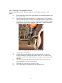
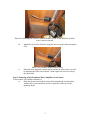
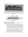
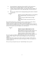
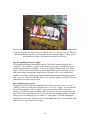
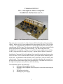
Cinnamon Hill Art
Rev.5 Headphone Mixer/Amplifier
Installation Instructions (rev.1)
Photo #1: The Cinnamon Hill Art Headphone Mixer/Amplifier Rev.5.
This is the latest version (Rev.5) of the Cinnamon Hill Art Headphone Mixer/Amplifier
(HMA). When you plug in your headphones the organ speakers go silent. This is called
“muting”. The Cinnamon Hill Art HMA has an internal MUTE function eliminating the
external organ MUTE wiring. This also means that the HMA is no longer restricted to the
Allen Organ amplifiers containing a Mute function. Any other brand can use the
Headphone Mixer/Amplifier as long as you can find the organ amplifier inputs and they
are RCA plugs and jacks. Drawing #2 on page 7 explains how the HMA is connected.
Installing the Cinnamon Hill Art Headphone Mixer/Amplifier should not take more than
one or two hours. You will then be able to listen to your organ without disturbing others
in the room. The installation in this manual is on my Allen ADC 3100 two manual, fourchannel organ. There are no connections to the organ other than the audio outputs from
the organ mixer and the audio inputs to the organ amplifier. The HMA has no effect on
the organ sound going to your speaker(s) other than muting.
The installation requires four main steps:
1)
Mounting of the headphone jack box
2)
Mounting of the Headphone Mixer/Amplifier circuit board and testing the
Jack Box.
3)
Wiring the audio cables
4)
Installing the power supply
1
Step 1: Mounting of the headphone jack box.
Tools needed: Electric drill, 1” diameter spade bit, awl, Phillips screwdriver, cable
clamps.
a)
Decide upon which side of the organ console you want the headphone jack
box to be located.
b)
Open the organ top panel and drill the 1” diameter hole (1-1/8” diameter
would be better if you have such a bit) in the approximate location desired
(see photo #2). To obtain a nice clean cut, drill from the top until the point
of the bit starts to show on in underside of the panel. Then drill from the
underside to meet the already-drilled section.
Photo #2: Drilling the hole for the Jack Box wiring.
c)
d)
e)
f)
g)
Vacuum up all wood chips.
Feed the connector through the hole from the underside. If you have
difficulty feeding the connector through the hole you will need to file a
small groove on one side of the hole to give clearance to one corner of the
connector.
Place the Jack Box in the desired location and using an awl, mark the
panel through the two box mounting holes.
Mount the box using the two screws provided.
Use a cable clamp to secure the box wire (see photo #3a).
2
Photo #3a: Mounting the Jack Box underneath the key bed. In this photo the jack box
cover is shown removed.
h)
i)
Install the cover to the Jack Box using the four screws provided (see photo
#3b).
Photo # 3b: Jack Box mounted and covered.
Route the wire inside the console until it reaches the place where you will
be installing the HMA circuit board. Allen Organ uses wire ties to keep
the cables neat.
Step 2: Mounting of the Headphone Mixer/Amplifier circuit board.
Tools needed: Awl, Phillips screwdriver.
a)
Place the circuit board in the location desired against the wooden panel
with the RCA jacks up and use an awl to mark one of the top corner
mounting holes.
3
b)
c)
d)
Remove the circuit board and use the awl to redefine the mark (make it
deeper).
Insert one of the 1-1/4” long screws through the circuit board mounting
hole and into the wood. Use the screwdriver to turn the screw a few turns,
just enough to hold the circuit board from falling down, allowing the
board to be held flush against the wood panel.
Hold the circuit board so that it is horizontal and mark the other three
holes with the awl (see photo #4).
Photo #4: Mounting the HMA circuit board. Using awl to mark location of right side
mounting hole. The left side screw is temporarily used to hold board up. Note the towel
below to prevent dropped screws from doing any damage.
4
e)
f)
g)
h)
i)
j)
Remove the screw and use the awl to redefine the remaining three
mounting hole awl marks.
Reinsert the first screw into the circuit board but this time use one of the
provided hollow spacers behind the circuit board. Do not tighten the
screw yet. Leave some slack. This will give your fingers enough room to
go behind the circuit board to hold the spacers as you snug up the screws.
Insert the opposite top screw with the spacer behind it and screw it in but
not all the way.
Repeat (g) for the remaining two mounting screws and spacer.
Go to each screw and snug it up. Snug, not tighten. Just snug the screw
enough to eliminate any movement at the mounting hole location. Again,
do not use excessive force to snug the screw (see photo #5). This process
will prevent the circuit board from being distorted and causing a
malfunction.
Insert the Jack Box cable plug into the connector at the bottom of the
HMA circuit board.
Photo #5: The HMA circuit board mounted with the Jack Box connector in place. Notice
the use of the Allen Organ wire ties on the left holding the Jack Box cable.
Testing the operation of the Jack Box:
Temporarily plug in the power supply into a wall outlet. Insert the round cable
plug into the HMA circuit board power connector at the upper right. Notice the two
LEDs at the left side of the circuit board. The lower green LED will indicate that the
board is powered up. The upper blue LED, the “Amp Active” LED, should be lit also.
Now, plug in a headphone into the Jack Box. The blue LED should extinguish.
5
Step #3: Wiring the audio cables:
Photo #6: Rear view of the RCA jacks and the power jack. Starting from the right, the
three groups of RCA jacks are for channels #1 to 6, inputs and outputs. Channel #1 is at
the right. The red RCA jack are inputs and the white RCA jacks are outputs. The fourth
group on the left are for other functions. See the drawing #1 below for an explanation of
each RCA jack.
Drawing #1
Further Explanation of Inputs and Outputs
The drawing #2 below gives an “in position” view. This makes it easier to understand
the operation of the HMA inputs and outputs.
Here is how the HMA works (refer to the white inset in the diagram below):
a)
Channel #1 output from the organ mixer is sent to the “HMA Audio Input”,
channel #1. This signal is then sent to the relay (see inset) where either it is
connected to the “HMA Audio Output” (headphones NOT plugged in) or it is
NOT connected to the “HMA Audio Output” (headphones are plugged in).
b)
The “HMA Audio Output” is connected to the organ amplifier and speaker as
channel #1. Note that the HMA does not change the audio signal. All HMA
does is switch the audio signal between the incoming channel audio or
ground. When the “HMA Audio Output” is grounded, there is “0” voltage at
the amplifier input which means that the amplifier will not send out any signal
to the loud speaker. This occurs when the headphone is plugged in.
c)
Note also that each channel is amplified, mixed and sent to the earphones.
Channels #1, 2 and 3 are mixed and appear at the LEFT monitor output.
Channels #4, 5 and 6 are mixed and appear at the RIGHT monitor output.
6
d)
In c) above, it was assumed that the Mono/Stereo select jumper was in the
“Stereo” position. If the user prefers to have all the channels mixed and
appear in both sides of the headphones at the same time, then “Mono” should
be selected.
Drawing #2
It is now time to wire the audio cables from the organ mixer board to the HMA.
a)
Label each cable coming from the mixer using whatever method you desire
(see photo #7 below). Noticed that I wrote on the RCA plug using a magic
marker, “3” (lower left). “1” and “4” can also be seen in the photo.
Photo #7: The Allen Organ model ADC Mixer Board. On this organ there are four
channels of outputs (bottom of photo) in this order: Channel #3, 1, 2, & 4. The other end
of these four RCA cables are plugged into the “HMA audio input” jacks (the red jacks).
7
b)
Start with channel #1 and plug a male-to-male RCA cable into the mixer
board and run it to the HMA channel #1 red RCA input connector.
c)
Continue with the remaining channels. My organ only had four channels. If
yours has six then do all six. After connecting cables, route them using wire
ties.
d)
Here are some examples in the wiring depending upon the number of channels
you may have:
Channels:
2
Channel #1 plugs into HMA channel #1 (Left earphone)
HMA channels #2 and 3 are not used. Set to zero
volume.
Channel #2 plugs into HMA channel #4 (Right
earphone)
HMA channels #5 and 6 are not used. Set to zero
volume.
Result: With the Mono/Stereo jumper in the “Stereo” position, the organist will hear
Channel #1 in the left earphone and Channel #2 in the right earphone.
With the Mono/Stereo jumper in the “Mono” position, the organist will hear Channel #1
and #2 in the left ear AND in the right ear. There is no separation of the sound. This may
be OK to the organist because the earphones are used for practice.
Channels:
4
Channel #1 plugs into HMA channel #1 (Left)
Channel #2 plugs into HMA channel #2 (Left)
HMA channel #3 not used. Set volume control to zero.
Channel #3 plugs into HMA channel #4 (Right)
Channel #4 plugs into HMA channel #5 (Right)
HMA channel #6 not used. Set volume control to zero.
Result: (See photo #8) With the Mono/Stereo jumper in the “Stereo” position, the
organist will hear Channel #1 and #2 in the left earphone and #3 and 4 in the right
earphone.
With the Mono/Stereo jumper in the “Mono” position, the organist will hear all four
channels in the left ear and all four channels in the right ear. There is no separation of
sound (see photo #9).
How you set up your organ is up to you. Experimenting is easy so go to it!
8
Setting the volume controls:
Start by setting all the volume controls to 11 O’clock. Connect your headphones
and play some music. If you hear any imbalance correct by increasing (clockwise) or
decreasing (counter-clockwise) the volume of a channel. If you need more volume in one
ear or the other, adjust the corresponding controls, “Left” or “Right” at the “Output
Volume” section (see drawing below).
Headphones vary in efficiency so the “Output Volume” controls will account for this.
Low efficiency headphones will need the volume increased.
Photo #8: The completed installation. In this photo the HMA channel #1 is shown at the
extreme left. The lower RED jacks (those nearest the wooden panel) are the HMA
inputs, and the upper jacks are the audio outputs to the amplifier (white jacks).
With the red jumper in the “Stereo” position the Allen Organ channels #1 and #2 will be
heard in the left earphone. The Allen Organ channels #3 and #4 will be heard in the right
earphone. If the red jumper is placed in the “Mono” position, then all four channels will
be heard in each earphone.
9
Photo #9: Initially this wiring was used. As can be seen, channel 1, 2, and 3 will be heard
in the left earphone and channel #4 in the right IF “Stereo” is chosen. Now, if “Mono” is
chosen then all four channels will be heard in the left and right earphone. There will be
no separation of sound. This choice is entirely up to the user.
Step #4: Installing the power supply:
The included wall adapter (sometimes called a “Wall Wart”) must be plugged into a
“switched” 120-volt outlet. In other words, whenever the organ is switched on, power
should be applied to the wall adapter. It is easy to find the switched outlet in an Allen
Organ. They are labeled and if there are not enough outlets, you can purchase a power
strip and use that to expand the switched power (see photo #10). In my installation I
could have used the available Allen Organ switched outlet instead of installing a power
strip. However, I intend to add other items to my organ that require a switched 120 volts.
I added the power strip for that reason.
How to mount a power strip:
Finding the locations of the two mounting holes for the power strip is easy if you do a
“rubbing” of the rear of the power strip on a piece of 8-1/2 x 11 paper. A pencil should
be used for this purpose. The “keyhole” screw mounting holes will be seen on the
rubbing. All you have to do is to trim the paper to the size of the power strip, locate the
paper where desired, and then use an awl to mark where the mounting holes are located.
Then screw in a round head screw to within 1/8” of the panel. Check the mounting by
installing the power strip. If the strip is loose then tighten the screw a bit and check again
until the power strip is held firmly in place.
10
Photo #10: Mounting of a Power Strip for the Wall Adapter (“wall wart”).
Additional information:
On the RCA jack panel there is one jack that can be used to add an external LED. This
LED is used to indicate that the amplifiers are active. Here is how you wire it:
HMA R5 Installation Manual R1
Dec. 2014
11