1
Dialogic® AG 2000C
CompactPCI Media Board
Installation and Developer’s
Manual
October 2009
64-0489-01
www.dialogic.com
Dialogic® AG 2000C CompactPCI Media Board Installation and Developer’s Manual
Copyright and legal notices
Copyright © 2001-2009 Dialogic Corporation. All Rights Reserved. You may not reproduce this document in
whole or in part without permission in writing from Dialogic Corporation at the address provided below.
All contents of this document are furnished for informational use only and are subject to change without notice
and do not represent a commitment on the part of Dialogic Corporation or its subsidiaries (“Dialogic”).
Reasonable effort is made to ensure the accuracy of the information contained in the document. However,
Dialogic does not warrant the accuracy of this information and cannot accept responsibility for errors,
inaccuracies or omissions that may be contained in this document.
INFORMATION IN THIS DOCUMENT IS PROVIDED IN CONNECTION WITH DIALOGIC® PRODUCTS. NO LICENSE,
EXPRESS OR IMPLIED, BY ESTOPPEL OR OTHERWISE, TO ANY INTELLECTUAL PROPERTY RIGHTS IS GRANTED BY
THIS DOCUMENT. EXCEPT AS PROVIDED IN A SIGNED AGREEMENT BETWEEN YOU AND DIALOGIC, DIALOGIC
ASSUMES NO LIABILITY WHATSOEVER, AND DIALOGIC DISCLAIMS ANY EXPRESS OR IMPLIED WARRANTY,
RELATING TO SALE AND/OR USE OF DIALOGIC PRODUCTS INCLUDING LIABILITY OR WARRANTIES RELATING
TO FITNESS FOR A PARTICULAR PURPOSE, MERCHANTABILITY, OR INFRINGEMENT OF ANY INTELLECTUAL
PROPERTY RIGHT OF A THIRD PARTY.
Dialogic products are not intended for use in medical, life saving, life sustaining, critical control or safety systems,
or in nuclear facility applications.
Due to differing national regulations and approval requirements, certain Dialogic products may be suitable for use
only in specific countries, and thus may not function properly in other countries. You are responsible for ensuring
that your use of such products occurs only in the countries where such use is suitable. For information on specific
products, contact Dialogic Corporation at the address indicated below or on the web at www.dialogic.com.
It is possible that the use or implementation of any one of the concepts, applications, or ideas described in this
document, in marketing collateral produced by or on web pages maintained by Dialogic may infringe one or more
patents or other intellectual property rights owned by third parties. Dialogic does not provide any intellectual
property licenses with the sale of Dialogic products other than a license to use such product in accordance with
intellectual property owned or validly licensed by Dialogic and no such licenses are provided except pursuant to a
signed agreement with Dialogic. More detailed information about such intellectual property is available from
Dialogic’s legal department at 9800 Cavendish Blvd., 5th Floor, Montreal, Quebec, Canada H4M 2V9. Dialogic
encourages all users of its products to procure all necessary intellectual property licenses required to implement
any concepts or applications and does not condone or encourage any intellectual property infringement and
disclaims any responsibility related thereto. These intellectual property licenses may differ from country to
country and it is the responsibility of those who develop the concepts or applications to be aware of and comply
with different national license requirements.
Any use case(s) shown and/or described herein represent one or more examples of the various ways, scenarios
or environments in which Dialogic® products can be used. Such use case(s) are non-limiting and do not
represent recommendations of Dialogic as to whether or how to use Dialogic products.
Dialogic, Dialogic Pro, Brooktrout, Diva, Cantata, SnowShore, Eicon, Eicon Networks, NMS Communications, NMS
(stylized), Eiconcard, SIPcontrol, Diva ISDN, TruFax, Exnet, EXS, SwitchKit, N20, Making Innovation Thrive,
Connecting to Growth, Video is the New Voice, Fusion, Vision, PacketMedia, NaturalAccess, NaturalCallControl,
NaturalConference, NaturalFax and Shiva, among others as well as related logos, are either registered
trademarks or trademarks of Dialogic Corporation or its subsidiaries. Dialogic's trademarks may be used publicly
only with permission from Dialogic. Such permission may only be granted by Dialogic’s legal department at 9800
Cavendish Blvd., 5th Floor, Montreal, Quebec, Canada H4M 2V9. Any authorized use of Dialogic's trademarks will
be subject to full respect of the trademark guidelines published by Dialogic from time to time and any use of
Dialogic’s trademarks requires proper acknowledgement.
Windows is a registered trademark of Microsoft Corporation in the United States and/or other countries. The
names of actual companies and product mentioned herein are the trademarks of their respective owners.
This document discusses one or more open source products, systems and/or releases. Dialogic is not responsible
for your decision to use open source in connection with Dialogic products (including without limitation those
referred to herein), nor is Dialogic responsible for any present or future effects such usage might have, including
without limitation effects on your products, your business, or your intellectual property rights.
2
Dialogic Corporation
Dialogic® AG 2000C CompactPCI Media Board Installation and Developer’s Manual
Revision History
Revision
Release date
Notes
9000-60089-10
June 2001
SRG
9000-60089-11
August 2001
SRG
9000-60089-12
November 2001
MVH
9000-60089-13
May 2002
NBS, Natural Access 2002-1
9000-60089-14
November 2002
MVH, Natural Access 2003-1 Beta
9000-60089-15
April 2003
MVH, Natural Access 2003-1
9000-60089-16
April 2004
SRG, Natural Access 2004-1
64-0489-01
October 2009
LBG, NaturalAccess R9.0
Last modified: September 12, 2009
Refer to www.dialogic.com for product updates and for information about support
policies, warranty information, and service offerings.
Dialogic Corporation
3
Table Of Contents
Chapter 1: Introduction .................................................................................9
Chapter 2: Terminology ...............................................................................11
Chapter 3: Overview of the AG 2000C board ................................................13
AG 2000C board features ............................................................................13
Software components .................................................................................15
Natural Access ........................................................................................16
NMS OAM ...............................................................................................16
Configuration files ...................................................................................17
Runtime software ....................................................................................18
Trunk control programs (TCPs) ..................................................................18
Chapter 4: Installing the hardware ..............................................................19
Installation summary ..................................................................................19
AG driver software...................................................................................19
System requirements..................................................................................20
Keying the chassis......................................................................................20
Installing the board ....................................................................................23
Using the Hot Swap features ........................................................................24
Connecting to the telephone network ............................................................25
Ferrite block ...........................................................................................27
Developer's cable kit ................................................................................28
Chapter 5: Configuring the board.................................................................29
Adding board configurations to the NMS OAM database....................................29
Configuring and starting the system with oamsys............................................30
Using board keyword files............................................................................30
Creating a system configuration file for oamsys ..............................................32
Sample system configuration file ...............................................................33
Running oamsys.........................................................................................33
Changing configuration parameter settings ....................................................34
.leo files .................................................................................................34
Specifying configuration file locations ............................................................34
QSLAC files and trunk control programs.........................................................35
Naming conventions for QSLAC files ...........................................................35
Trunk control programs ............................................................................36
QSLAC files and TCPs for loop start ............................................................36
Configuring board clocking...........................................................................36
AG 2000C clocking capabilities ..................................................................37
Clock configuration methods .....................................................................39
Configuring AG 2000C boards using board keywords ....................................39
Multiple board system example..................................................................41
Enabling echo cancellation ...........................................................................42
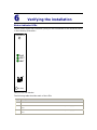
Chapter 6: Verifying the installation ............................................................43
Status indicator LEDs..................................................................................43
Verifying board installation ..........................................................................44
Retrieving AG board configuration information: boardinf ..................................44
Interactive test program: ctatest ..................................................................45
Dialogic® AG 2000C CompactPCI Media Board Installation and Developer’s Manual
Using swish for a standalone board ............................................................45
Using ctatest with an AG 2000C loop start board..........................................46
Demonstration programs .............................................................................47
Chapter 7: AG 2000C switching....................................................................49
AG 2000C switch model ..............................................................................49
H.110 streams ........................................................................................49
Local streams .........................................................................................49
Switch model ..........................................................................................50
Lucent T8100A switch blocking ..................................................................50
Signaling modules and logical timeslots .........................................................51
Default connections ....................................................................................51
Chapter 8: Configuration parameters...........................................................53
Using the Switching service .........................................................................53
Function information ................................................................................53
Line gain configuration ................................................................................54
Getting the line gain ................................................................................54
Setting the line gain.................................................................................56
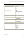
Chapter 9: Keyword summary......................................................................59
Using keywords..........................................................................................59
Setting keyword values ............................................................................60
Retrieving keyword values ........................................................................60
Editable keywords ......................................................................................61
Informational keywords...............................................................................62
Retrieving board information .....................................................................62
Retrieving EEPROM information .................................................................62
Retrieving board driver information ............................................................63
Plug-in keywords........................................................................................63
Chapter 10: Keyword reference ..................................................................65
Using the keyword reference........................................................................65
AutoStart ..................................................................................................66
AutoStop...................................................................................................67
Boards[x]..................................................................................................68
BootDiagnosticLevel ...................................................................................69
Buffers[x].Num ..........................................................................................72
Buffers[x].Size...........................................................................................73
Clocking.HBus.AutoFallBack .........................................................................74
Clocking.HBus.ClockMode ............................................................................76
Clocking.HBus.ClockSource..........................................................................77
Clocking.HBus.FallBackClockSource ..............................................................78
Clocking.HBus.NetRefSource ........................................................................79
Clocking.HBus.NetRefSpeed .........................................................................80
Clocking.HBus.Segment ..............................................................................81
DLMFiles[x] ...............................................................................................82
DSP.C5x.Lib ..............................................................................................83
DSP.C5x.Loader .........................................................................................84
DSP.C5x[x].Files[y] ....................................................................................85
DSP.C5x[x].Image .....................................................................................88
DSP.C5x[x].Os...........................................................................................89
Echo.AutoSwitchingRefSource ......................................................................90
6
Dialogic Corporation
Dialogic® AG 2000C CompactPCI Media Board Installation and Developer’s Manual
Echo.EnableExternalPins..............................................................................91
LoadFile ....................................................................................................92
LoadSize ...................................................................................................93
Location.PCI.Bus ........................................................................................94
Location.PCI.Slot........................................................................................95
MaxChannels .............................................................................................96
Name .......................................................................................................97
NetworkInterface.Analog[x].ConfigFile...........................................................98
Number ....................................................................................................99
Products[x] ............................................................................................. 100
RunFile ................................................................................................... 101
SignalIdleCode......................................................................................... 102
SwitchConnections ................................................................................... 103
SwitchConnectMode.................................................................................. 104
TCPFiles[x].............................................................................................. 105
Version.Major .......................................................................................... 106
Version.Minor .......................................................................................... 107
VoiceIdleCode.......................................................................................... 108
Xlaw....................................................................................................... 109
Chapter 11: Hardware specifications ........................................................111
General hardware specifications ................................................................. 111
Mechanical specifications ........................................................................ 111
H.110 compliant interface ....................................................................... 111
Host interface ....................................................................................... 112
Environment ......................................................................................... 112
Power requirements ............................................................................... 112
Common electrical specifications (United States version) ............................... 113
High impedance recording and caller ID mode .............................................. 114
QSLAC files and impedances ...................................................................... 114
Compliance and regulatory certification ....................................................... 115
EMC .................................................................................................... 115
Safety.................................................................................................. 115
Telecom ............................................................................................... 115
EU R&TTE statement .............................................................................. 115
Chapter 12: Managing resources ..............................................................117
Functions for managing resources............................................................... 117
Default functions ................................................................................... 117
Custom functions................................................................................... 118
DSP/task processor files and processing power ............................................. 119
AG 2000C board processing ....................................................................... 126
Chapter 13: Loop start signaling ..............................................................127
Signaling overview ................................................................................... 127
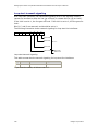
Loop start transmit signaling...................................................................... 128
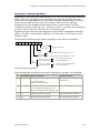
Loop start receive signaling ....................................................................... 129
Chapter 14: Natural Access migration ......................................................131
Migration overview ................................................................................... 131
NMS OAM................................................................................................ 131
Configuration file changes ......................................................................... 131
Keyword changes ..................................................................................... 132
Dialogic Corporation
7
1
Introduction
The Dialogic® AG 2000C CompactPCI Media Board Installation and Developer’s
Manual explains how to configure and install an AG 2000C board, and how to verify
that it has been installed correctly and is operating correctly. It also provides general
information about developing an application that uses the AG 2000C board.
This manual targets developers of telephony and voice applications who are using
the AG 2000C board with Natural Access. This manual defines terms where
applicable, but assumes that readers are familiar with telephony concepts, switching,
and the C programming language.
2
Terminology
Note: The product to which this document pertains is part of the NMS
Communications Platforms business that was sold by NMS Communications
Corporation (“NMS”) to Dialogic Corporation (“Dialogic”) on December 8, 2008.
Accordingly, certain terminology relating to the product has been changed. Below is
a table indicating both terminology that was formerly associated with the product, as
well as the new terminology by which the product is now known. This document is
being published during a transition period; therefore, it may be that some of the
former terminology will appear within the document, in which case the former
terminology should be equated to the new terminology, and vice versa.
Former terminology
Dialogic terminology
CG 6060 Board
Dialogic® CG 6060 PCI Media Board
CG 6060C Board
Dialogic® CG 6060C CompactPCI Media Board
CG 6565 Board
Dialogic® CG 6565 PCI Media Board
CG 6565C Board
Dialogic® CG 6565C CompactPCI Media Board
CG 6565e Board
Dialogic® CG 6565E PCI Express Media Board
CX 2000 Board
Dialogic® CX 2000 PCI Station Interface Board
CX 2000C Board
Dialogic® CX 2000C CompactPCI Station Interface Board
AG 2000 Board
Dialogic® AG 2000 PCI Media Board
AG 2000C Board
Dialogic® AG 2000C CompactPCI Media Board
AG 2000-BRI Board
Dialogic® AG 2000-BRI Media Board
NMS OAM Service
Dialogic® NaturalAccess™ OAM API
NMS OAM System
Dialogic® NaturalAccess™ OAM System
NMS SNMP
Dialogic® NaturalAccess™ SNMP API
Natural Access
Dialogic® NaturalAccess™ Software
Natural Access Service
Dialogic® NaturalAccess™ Service
Fusion
Dialogic® NaturalAccess™ Fusion™ VoIP API
ADI Service
Dialogic® NaturalAccess™ Alliance Device Interface API
CDI Service
Dialogic® NaturalAccess™ CX Device Interface API
Digital Trunk Monitor Service
Dialogic® NaturalAccess™ Digital Trunk Monitoring API
MSPP Service
Dialogic® NaturalAccess™ Media Stream Protocol
Processing API
Natural Call Control Service
Dialogic® NaturalAccess™ NaturalCallControl™ API
NMS GR303 and V5 Libraries
Dialogic® NaturalAccess™ GR303 and V5 Libraries
Dialogic® AG 2000C CompactPCI Media Board Installation and Developer’s Manual
Former terminology
Dialogic terminology
Point-to-Point Switching Service
Dialogic® NaturalAccess™ Point-to-Point Switching API
Switching Service
Dialogic® NaturalAccess™ Switching Interface API
Voice Message Service
Dialogic® NaturalAccess™ Voice Control Element API
NMS CAS for Natural Call Control
Dialogic® NaturalAccess™ CAS API
NMS ISDN
Dialogic® NaturalAccess™ ISDN API
NMS ISDN for Natural Call Control
Dialogic® NaturalAccess™ ISDN API
NMS ISDN Messaging API
Dialogic® NaturalAccess™ ISDN Messaging API
NMS ISDN Supplementary Services
Dialogic® NaturalAccess™ ISDN API Supplementary
Services
NMS ISDN Management API
Dialogic® NaturalAccess™ ISDN Management API
NaturalConference Service
Dialogic® NaturalAccess™ NaturalConference™ API
NaturalFax
Dialogic® NaturalAccess™ NaturalFax™ API
SAI Service
Dialogic® NaturalAccess™ Universal Speech Access API
NMS SIP for Natural Call Control
Dialogic® NaturalAccess™ SIP API
NMS RJ-45 interface
Dialogic® MD1 RJ-45 interface
NMS RJ-21 interface
Dialogic® MD1 RJ-21 interface
NMS Mini RJ-21 interface
Dialogic® MD1 Mini RJ-21 interface
NMS Mini RJ-21 to NMS RJ-21 cable
Dialogic® MD1 Mini RJ-21 to MD1 RJ-21 cable
NMS RJ-45 to two 75 ohm BNC splitter
cable
Dialogic® MD1 RJ-45 to two 75 ohm BNC splitter cable
NMS signal entry panel
Dialogic® Signal Entry Panel
12
Dialogic Corporation
3
Overview of the AG 2000C
board
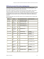
AG 2000C board features
The AG 2000C board is part of the Alliance Generation family of telephony boards. It
provides 8, 16, or 24 analog loop start interfaces with call control and switching in a
single CompactPCI slot.
Refer to the NMS web site (www.nmscommunications.com) for a list of available AG
2000C board configurations, for a list of countries where NMS has obtained approval
for the AG 2000C board, and for product updates.
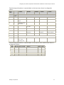
An AG 2000C board contains the following main features:
•
DSP resources
Each board has four high-performance digital signal processors (DSPs). The
following table provides information about the different AG 2000C models:
Model
Ports
AG 2000C-8
8
Capabilities
Eight universal ports (Call control, IVR, fax, and VoIP).
Note: Conferencing can be substituted for fax or VoIP.
AG 2000C-16
16
Call control, switching, IVR, and fax or conferencing
AG 2000C-24
24
Call control and switching
IVR is defined as play or record and DTMF detection.
•
CompactPCI bus connectivity
Each AG 2000C board is designed to reside in a single CompactPCI bus slot.
Each board contains a 5 volt CompactPCI bus interface compliant with the
CompactPCI Specification PICMG 2.0 R2.1. The CompactPCI interface is a 33
MHz, 32-bit target device.
•
H.110 bus connectivity
The AG 2000C board fully supports the H.110 bus specification. The H.110
bus enables boards to share data and signaling information with other boards
on the H.110 bus. For example, you can connect two or more AG 2000C
boards for applications that perform trunk-to-trunk switching. You can add
additional DSP resources, analog station interfaces, or loop start line
interfaces using other AG boards. You can also use H.110 compatible products
from other manufacturers with the AG 2000C board.
•
Telephony bus switching
Switching for the AG 2000C board is implemented with the T8100A chip. The
T8100A is a single chip that offers full support for the H.110 bus within the
H.110 architecture providing access to all 4096 slots.
On the AG 2000C board, switch connections are allowed for up to 128 full
duplex connections between local devices and the H.110 bus.
Dialogic® AG 2000C CompactPCI Media Board Installation and Developer’s Manual
•
Loop start line interface signaling modules
The AG 2000C board has two to six loop start line interface signaling modules
which are circuits that connect a bidirectional transmission channel to
separate receive and transmit channels. Each line interface signaling module
has four ports. This allows you to monitor and control at least 8 channels of
signaling information.
The loop start line interface signaling module replaces a telephone, modem,
or fax machine at the end of a standard telephone line or PBX extension.
The loop start interface can also be a trunk interface to the telephone
network. With loop start trunks, you may want to segregate incoming calls
from outgoing calls to avoid collisions between the two.
Changing the interface model has no impact on applications that you have
already written.
The loop start interface:
•
Has very high tolerance to common mode power line interfaces.
•
Detects loop current reversals and interruptions in the off-hook mode.
•
Receives called party identification in some countries.
•
Records calls in on-hook mode where permitted by regulations.
Do not change any of the settings on the line interface signaling modules or attempt
to remove the modules. These settings are factory installed and tested.
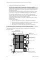
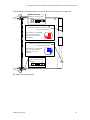
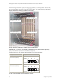
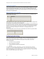
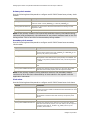
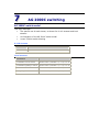
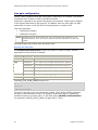
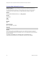
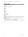
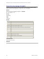
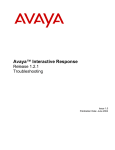
The following illustration shows where various components are located on an
AG 2000C board:
T8100A switch
makes connections for H.110
streams and local streams
TNV3 level keys
J5
Telephony I/O
connects to rear panel I/O
Four signaling
modules
H.110 connector
connects to H.110 bus
Strawberry red key
J3
Status
indicator
LEDs
Brilliant blue key
Hot
Swap
LED
TNV3 level keys
14
PCI bus connector
communicates with host
Dialogic Corporation
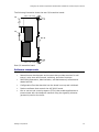
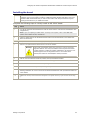
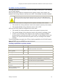
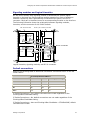
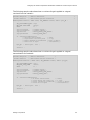
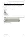
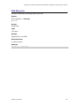
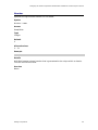
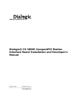
Dialogic® AG 2000C CompactPCI Media Board Installation and Developer’s Manual
The following illustration shows the rear I/O transition board:
TNV3 level keys
J5
J3
RJ-21
TNV3 level keys
Rear I/O transition board
Software components
AG 2000C boards require the following software components:
•
Natural Access development environment that provides services for call
control, voice store and forward, switching, and other functions.
•
NMS OAM (Operations, Administration, and Maintenance) software and
related utilities.
•
Configuration files that describe how the board is set up and initialized.
•
Runtime software that controls the AG 2000C board.
•
One or more trunk control programs (TCPs) that enable applications to
communicate with the telephone network using the signaling schemes
(protocols) used on the trunk.
Dialogic Corporation
15
Dialogic® AG 2000C CompactPCI Media Board Installation and Developer’s Manual
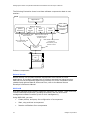
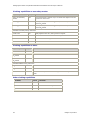
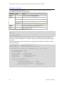
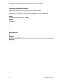
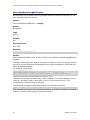
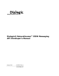
The following illustration shows how these software components relate to one
another:
Host
Application
Natural Access
(Other
services)
ADI
service
ADI commands and
board events
NCC
service
OAM
service
NMS OAM
configuration
database
Natural Call Control
commands and
board events
NMS OAM configuration
commands,
information, and
board events
API commands and
board events
AG board
driver
TCP
Runtime
Software components
Natural Access
Natural Access is a complete software development environment for voice
applications. It provides a standard set of functions grouped into logical services.
Each service has a standard programming interface. For more information about
standard and optional Natural Access services, refer to the Natural Access
Developer's Reference Manual.
NMS OAM
NMS OAM manages and maintains telephony resources in a system. These resources
include hardware components (including AG boards) and low-level board
management software modules (such as clock management).
Using NMS OAM, you can:
16
•
Create, delete, and query the configuration of a component
•
Start, stop, and test a component
•
Receive notifications from components
Dialogic Corporation
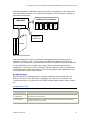
Dialogic® AG 2000C CompactPCI Media Board Installation and Developer’s Manual
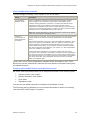
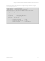
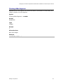
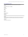
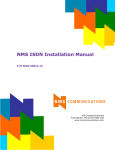
NMS OAM maintains a database containing records of configuration information for
each component as shown in the following illustration. This information consists of
parameters and values.
Con figu ration datab a se
NMS OA M
Board
plug-in
Clock
mgmt.
OAM
Supv.
Board
B
Board
A
Board plug-in
Software
components
Boards
A
B
NMS OAM components
Each parameter and value is expressed as a keyword name and value pair (for
example, AutoStart = NO). You can query the NMS OAM database for keyword
values for any component. Keywords and values can be added, modified, or deleted.
To use NMS OAM or any related utility, ensure that the Natural Access Server
(ctdaemon) is running. For more information about ctdaemon, refer to the Natural
Access Developer's Reference Manual. For more information about NMS OAM, refer
to the NMS OAM System User's Manual.
AG board plug-in
NMS OAM uses the AG board plug-in software module to communicate with AG
boards. The name of the AG plug-in is agplugin.bpi. This file must reside in the
\nms\bin directory (or /opt/nms/lib for UNIX) for NMS OAM to load it when it starts
up.
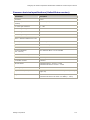
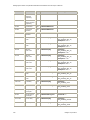
Configuration files
NMS OAM uses two types of configuration files:
File type
Description
System
configuration
Contains a list of boards in the system and the name of one or more board
keyword files for each board.
Board keyword
Contains parameters to configure the board. These settings are expressed as
keyword name and value pairs.
Dialogic Corporation
17
Dialogic® AG 2000C CompactPCI Media Board Installation and Developer’s Manual
Several sample board keyword files are installed with Natural Access. Each of these
files configures the board to use a different protocol (for example, Wink Start or OffPremises Station). You can reference these files in your system configuration file or
modify them.
When you run the NMS OAM oamsys utility, it creates NMS OAM database records
based on the contents of the specified system configuration file and board keyword
files. oamsys directs NMS OAM to start the boards and configure them according to
the specified parameters. For more information, refer to Configuring and starting the
system with oamsys on page 30.
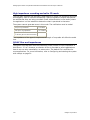
Runtime software
The runtime software consists of runfiles and DSP files. The runfile is the basic lowlevel software that an AG board requires to operate. DSP files enable the AG onboard digital signal processors to perform certain tasks, such as DTMF signaling,
voice recording, and playback.
Several runfiles and DSP program files are installed with Natural Access. Specify the
files to use for your configuration in the board keyword file. Refer to Using board
keyword files on page 30 for more information. When NMS OAM boots a board, the
runfiles and DSP program files are transferred from the host into on-board memory.
For more information about the DSP files shipped with Natural Access, refer to the
ADI Service Developer's Reference Manual.
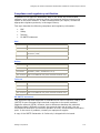
Trunk control programs (TCPs)
AG 2000C boards are compatible with a variety of signaling schemes called
protocols. To program an AG board for a specific protocol, a trunk control program
(TCP) is loaded on the board. The TCP performs all of the signaling tasks to interface
with the protocol used on the line.
Several different protocol standards are used throughout the world. These standards
differ considerably from country to country. For these reasons, different TCPs are
supplied with Natural Access for various protocols and country-specific variations.
You can load more than one TCP at a time for applications that support multiple
protocols simultaneously. TCPs are specified in the configuration file and are
downloaded to the board by oamsys. TCPs run on the board, relieving the host
computer from the task of processing the protocol directly. For more information
about TCPs, refer to the NMS CAS for Natural Call Control Developer's Manual.
18
Dialogic Corporation
4
Installing the hardware
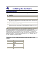
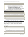
Installation summary
The following table summarizes the procedure for installing the hardware and
software components:
Step
Description
1
Ensure that your PC system meets the system requirements on page 20.
2
Install the board into one of the computer's CompactPCI bus slots.
3
Install Natural Access, which also installs the AG 2000C board driver and runtime software, and
NMS CAS protocols. Select the country where NMS CAS protocols is installed. This configures loop
start products for local compliance. For more information, refer to the NMS CAS for Natural Call
Control Developer's Manual.
4
Add configuration information for each board to the NMS OAM database. For more information,
refer to the NMS OAM System User's Manual.
5
Direct the OAM service to start the boards. For more information refer to Configuring and starting
the system with oamsys on page 30 and to the NMS OAM System User's Manual.
6
Verify that the installation is operational.
Note: If your system is powered down, you can install the board before you install
the software. It does not matter if you install the board or the software first.
The BootDiagnosticLevel keyword in the board keyword file determines the type of
board diagnostic tests that take place when you boot the board. If a test fails, the
test number is reported back as an error code. You must be running oammon to view
diagnostic results. For more information about board level error messages, refer to
the NMS Board and Driver Errors Manual.
AG driver software
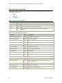
The following drivers for operating AG boards are installed with Natural Access
software:
Operating system
Driver names
Windows
aghwwin2k
agwin2k
UNIX
aghw
agsw
ag95sw
agmx
Red Hat Linux
aghw.o
Dialogic® AG 2000C CompactPCI Media Board Installation and Developer’s Manual
System requirements
To install and use AG 2000C boards, your system must have:
•
Natural Access installed.
•
A CompactPCI chassis with an H.110 compliant backplane and an available
CompactPCI bus slot.
Note: The AG 2000C board can power up and function only in a chassis with
a telephony backplane.
•
A grounded chassis (with a three-prong power cord).
NMS recommends an uninterruptable power supply (UPS) for increased system
reliability. The UPS does not need to power the PC video monitor except in areas
prone to severe lightning storms.
Keying the chassis
An AG 2000C has several mechanical interlocks, called keys, that prevent the board
from being inserted in an incompatible chassis. Keying protects the board and other
devices in the chassis from damage by ensuring that you will not accidentally insert
an incompatible board in the chassis.
Before you install AG 2000C boards, configure the keying of your chassis to be
compatible with the AG 2000C keying.
For detailed information on CompactPCI chassis keying, refer to the CompactPCI
Computer Telephony Specification PICMG 2.5 R1.0, to Keying of CompactPCI Boards
and Backplanes PICMG 2.10 R1.0, and to the IEEE 1101.10.
Warning:
To protect yourself and your equipment, use only qualified personnel to install keying. The
personnel must be familiar with the CompactPCI Computer Telephony Specification PICMG
2.5, R1.0 document.
Note: An AG 2000C board does not function in a chassis that does not have a
telephony backplane.
20
Dialogic Corporation
Dialogic® AG 2000C CompactPCI Media Board Installation and Developer’s Manual
The following illustration shows how the AG 2000C board keys are configured:
TNV3 level keys
Keyed as shown below:
Chamber: C
B
A
Position: 2
1
1
J4
Contains a female strawberry red
key as shown below:
This setting is compatible
only with CompactPCI
chassis with telephony
backplanes.
3
5 6 7
J1
Contains a female brilliant blue
key as shown below:
This setting is compatible
only with CompactPCI
chassis with 5.0V
signaling.
2 3 4
8
TNV3 level keys
Keyed as shown below:
Chamber: F
E
D
Position: 1
1
1
AG 2000C key configuration
Dialogic Corporation
21
Dialogic® AG 2000C CompactPCI Media Board Installation and Developer’s Manual
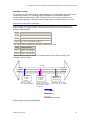
The following illustration shows the keying chambers in a CompactPCI chassis that
you must configure or verify for an AG 2000C board. You must also key rear panel
keying chambers A through F that are not shown.
Backplane connector
strawberry red keys (P4)
Front panel keying
chambers (A, B, and C)
Front panel keying
chambers (D, E, and F)
Backplane connector
brilliant blue keys (P1)
Keying chamber locations on chassis front and backplane
Chambers A, D, E, and F are defined by backplane wiring and network signaling
levels. Chambers B and C are manufacturer-specific.
Configure keying in the chassis as described in the following table:
Keying chambers on chassis
Configuration
A, B, and C
(Front and rear panels)
Configure as shown in this illustration:
D, E, and F
(Front and rear panels)
Chamber:
A
B
C
Position:
1
1
2
Configure as shown in this illustration:
Chamber:
D
E
F
Position:
1
1
1
P1 and P4 are installed by the backplane vendor.
22
Dialogic Corporation
Dialogic® AG 2000C CompactPCI Media Board Installation and Developer’s Manual
Installing the board
Caution:
The AG 2000C board is shipped in a protective anti-static container. Leave the board in its
container until you are ready to install it. Handle the board carefully and hold it only by its
handles. NMS recommends that you wear an anti-static wrist strap connected to a good
earth ground whenever you handle the board.
Complete the following steps to initially install an AG 2000C board:
Step
Action
1
Turn off the computer and disconnect it from the power source. (This step is suggested for new
configurations.)
Note: If you are replacing a board that is currently in the system, refer to the NMS OAM
System User's Manual for any restrictions.
2
Choose a chassis slot for the AG 2000C board. Remove the access panels to the chassis slot
(both rear and front).
3
Verify that the chassis slot has the appropriate keying.
4
Slide the rear I/O transition board into the rear of the chassis.
Warning:
Some older CompactPCI chassis may not have a rear I/O connector
alignment feature. The rear I/O transition board requires this feature
to allow insertion. Contact the chassis manufacturer to find out if your
chassis supports this rear alignment feature. Use caution when
inserting the board into the backplane mating connector.
5
Seat the rear I/O transition board by rotating the top and bottom handles.
6
Fasten the board to the chassis with the screws on the upper and lower handles.
7
Slide the AG 2000C board into the corresponding slot in the front of the chassis.
8
Seat the board into the backplane by rotating the top and bottom handles toward each other.
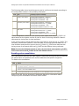
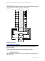
9
Fasten the board to the chassis with the screws on the upper and lower handles. Refer to the
following illustration for a view of how the AG 2000C board and the rear I/O transition board sit
in the chassis.
10
Replace the covers, and connect the computer to its power source (if you turned it off in Step
1).
Dialogic Corporation
23
Dialogic® AG 2000C CompactPCI Media Board Installation and Developer’s Manual
AG 2000C board
Trunks
5..8
Backplane
Rear I/O
transition board
Trunks
13..16
Front
of the
chassis
Trunks
17..20
Trunks
1..4
Back
of the
chassis
Trunks
9..12
Trunks
21..24
AG 2000C board installed with a rear I/O transition board
Using the Hot Swap features
Hot Swap operates only if the Hot Swap Driver and Hot Swap Manager are started.
To learn how to start these modules, refer to the NMS OAM System User's Manual.
Under Windows, you must also install additional drivers to enable NMS Hot Swap
drivers to interact properly with Windows Plug and Play functionality. These drivers
are available with Natural Access.
Once the Hot Swap Driver and Hot Swap Manager are started, boards defined in the
NMS OAM database may be booted, extracted, and reinserted. Boards inserted into a
PCI bus and slot for which no logical board definition exists in the database are not
recognized. For more information about configuring Hot Swap, refer to the NMS OAM
System User's Manual.
24
Dialogic Corporation
Dialogic® AG 2000C CompactPCI Media Board Installation and Developer’s Manual
Connecting to the telephone network
This topic provides instructions for connecting to the telephone network.
Warning:
Important safety notes for telephony connections
•
Allow only qualified technical personnel to install this board and associated telephone
wiring.
•
Make sure the PC chassis is grounded through the power cord or by other means
before connecting the telephone line.
•
Never install telephone wiring during a lightning storm.
•
Never install telephone jacks in wet locations.
•
Telephone companies provide primary lightning protection for their telephone lines.
However, if a site connects to private lines that leave the building, make sure that
external protection is provided.
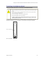
As shown in the following illustration, the end bracket on the AG 2000C rear I/O
transition board has an RJ-21 connector. The connector has 25-pair interfaces:
RJ-21 connector
NMS
TM
RJ-21 connector
Dialogic Corporation
25
Dialogic® AG 2000C CompactPCI Media Board Installation and Developer’s Manual
The connector is designed to accommodate a 25-pair cable. As shown in the
following illustration, this cable is commonly wired to a punch-down block or
breakout box.
AG 2000C
rear
transition
board
25 pair cable
66 or 110 punch-down block
or breakout box
Connecting the board
The RJ-21 connector on the cable must be the 180-degree design. The common 90degree RJ-21 connector is not compatible with the AG 2000C board.
90° RJ-21 connector
(not compatible
with AG 2000C
boards)
180° RJ-21
connector
(compatible with
AG 2000C boards)
90-degree versus 180-degree RJ-21 connector
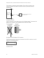
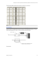
The following illustration shows the pin locations for the RJ-21 connector on an AG
2000C rear I/O transition board:
Pin 50 . . . . . . . . . . . . Pin
26
Pin 25 . . . . . . . . . . . . Pin
1
Connector pinout
26
Dialogic Corporation
Dialogic® AG 2000C CompactPCI Media Board Installation and Developer’s Manual
The following table describes the pinouts for the RJ-21 connector:
Trunk
Ring pin
Tip pin
Trunk
Ring pin
Tip pin
1
1
26
13
13
38
2
2
27
14
14
39
3
3
28
15
15
40
4
4
29
16
16
41
5
5
30
17
17
42
6
6
31
18
18
43
7
7
32
19
19
44
8
8
33
20
20
45
9
9
34
21
21
46
10
10
35
22
22
47
11
11
36
23
23
48
12
12
37
24
24
49
Note: Pins 25 and 50 are not used.
Ferrite block
The AG 2000C board is shipped with a ferrite block (P/N 33210). Attach the ferrite
block to the RJ-21 cable with one loop as shown in the following illustration. The AG
2000C board passes FCC Part 15, Class A without this ferrite block.
Ferrite block
2"
Loop wire once around the lower
section of the ferrite block
Ferrite block
Dialogic Corporation
27
Dialogic® AG 2000C CompactPCI Media Board Installation and Developer’s Manual
Developer's cable kit
To help you get started, NMS provides an optional developer's cable kit (P/N 80659).
The kit contains two 10-foot RJ-21 cables and two breakout boxes. Each breakout
box connects one RJ-21 to 24 standard RJ-11 (POTS) jacks for individual phones.
You can use the cables to connect to the breakout boxes or to standard 66 or 110
blocks.
All components of the developer's cable kit sold by NMS are also commercially
available from telephone product distributors such as Graybar and Anixter. These
distributors can provide variations in cable lengths.
28
Dialogic Corporation
5
Configuring the board
Adding board configurations to the NMS OAM database
Each board that NMS OAM configures and starts must have a separate set of
configuration parameters. Each parameter value is expressed as a keyword name
and value pair (for example, AutoStart = NO). You can use NMS OAM to retrieve
parameters for any component. These parameters (set through board keywords) can
be added, modified, or deleted.
Before using NMS OAM, make sure that the Natural Access Server (ctdaemon) is
running. For more information about the Natural Access Server (ctdaemon), refer to
the Natural Access Developer's Reference Manual.
The following utilities are shipped with NMS OAM:
Utility
Description
oamsys
Configures and starts up boards on a system-wide basis. Attempts to start all specified boards
based on system configuration files you supply.
oamcfg
Provides greater access to individual NMS OAM configuration functions.
oaminfo
Displays keywords and settings for one or more components. Can also set individual
keywords.
Refer to the NMS OAM System User's Manual for more information about oamsys and
oamcfg.
An application can control NMS OAM using OAM service functions. For more
information about the OAM service functions and about oaminfo, refer to the NMS
OAM Service Developer's Reference Manual.
Dialogic® AG 2000C CompactPCI Media Board Installation and Developer’s Manual
Configuring and starting the system with oamsys
To configure and start a system using the oamsys utility:
Step
Action
1
Install the boards and software as described in the installation summary on page 19.
2
Determine which board keyword file you will use, or edit one of the sample AG 2000C board
keyword files, to specify appropriate configuration information for each board. For more
information, refer to Using board keyword files on page 30.
3
Determine the PCI bus and slot locations of the boards using the pciscan utility. pciscan
identifies the NMS PCI boards installed in the system and returns each board's bus, slot,
interrupt, and board type.
4
Create a system configuration file, or edit a sample system configuration file, to point to all the
board keyword files for your system. Specify a unique name and board number for each board.
5
Start oammon to monitor the NMS OAM system and all NMS boards. For more information
about oammon, refer to the NMS OAM System User's Manual.
Start oammon before running oamsys. Keep oammon running to see the status of all boards in
your system and to view error and tracing messages.
6
Use oamsys to start all of the installed boards (ctdaemon must be running when you use
oamsys) according to the configuration information specified in the system configuration file
and any associated board keyword files. For more information, refer to Running oamsys on
page 33.
To determine the physical slot location of a specific board:
Operating
system
Procedure
Windows
Use pciscan to associate the PCI bus assignment to a physical board by flashing an
LED on the board. To flash the LED on a board, call pciscan with the PCI bus and PCI
slot locations.
UNIX
Use blocate to associate the PCI bus assignment to a physical board by flashing an
LED on the board. To flash the LED on a board, call blocate with the PCI bus and PCI
slot locations.
For information about pciscan and blocate, refer to the NMS OAM System User's
Manual.
Using board keyword files
A board keyword file contains a list of parameters and values to configure a board.
The board keyword file for each board is assigned to the board in another file, called
a system configuration file. When oamsys runs, it creates a record for each board in
the NMS OAM database, and stores the parameters and values of the board. It then
starts the board, configured as described in the database.
A sample set of board keyword files are installed by the Natural Access installation.
You can copy these files and modify them. The sample board keyword files are
located in the \ag\cfg subdirectory under the Natural Access installation directory.
30
Dialogic Corporation
Dialogic® AG 2000C CompactPCI Media Board Installation and Developer’s Manual
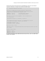
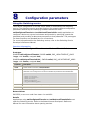
The following sample board keyword file (agpi2000c.cfg) shows the set of board
keywords necessary to configure and start an AG 2000C board:
#
#
#
AG Plug-in Config File for AG 2000C
# TCP files are shipped with the AG-CAS sub-package of Natural Access.
# Be sure that you installed the protocols that are specified below before
# trying to start a board with this configuration file.
TCPFiles[0] = nocc.tcp
TCPFiles[1] = lps0.tcp
# "no trunk control" protocol
# AG-CAS Loopstart protocol
# The SLAC file controls the line impedance.
# U.S. installations.
This is the SLAC file for
NetworkInterface.Analog[0..23].ConfigFile = a2usals6.slc
# This configures the board as stand alone - see documentation for options
# to use when the board needs to connect to the H.110 bus.
Clocking.HBus.ClockSource = OSC
Clocking.HBus.ClockMode = STANDALONE
# DSP (.m54) files to link in
DSP.C5x[0..3].Files = callp.m54 dtmf.m54 mf.m54 ptf.m54 signal.m54 tone.m54
XLaw = MU-LAW
voice.m54
# Runtime loadable modules
DLMFiles[0] = gtp.leo
DLMFiles[1] = voice.leo
DLMFiles[2] = svc.leo
For general information about NMS OAM board keyword files, refer to the NMS OAM
System User's Manual.
Dialogic Corporation
31
Dialogic® AG 2000C CompactPCI Media Board Installation and Developer’s Manual
Creating a system configuration file for oamsys
When your board keyword files are complete, create a system configuration file
describing all of the boards in your system. oamsys creates the records, and then
directs NMS OAM to start the boards, configured as specified. The system
configuration file is typically named oamsys.cfg. By default, oamsys looks for a file
with this name when it starts up. Refer to the NMS OAM System User's Manual for
specific information on the syntax and structure of this file.
Note: You can use the oamgen utility (included with the NMS OAM software) to
create a sample system configuration file for your system. The system configuration
file created by oamgen may not be appropriate for your configuration. You may need
to make further modifications to the file before running oamsys to configure your
boards based on the file. For more information about oamgen, refer to the NMS OAM
System User's Manual.
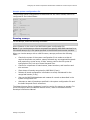
The following table describes the AG board-specific settings to include in the system
configuration file for each AG board:
Keyword
Description
Allowed values for AG boards
[name]
Name of the board to be used to
refer to the board in the software.
The board name must be unique.
Any string, in square brackets [].
Product
Name of the board product.
AG_2000C
Number
Board number you use in the
Natural Access application to refer
to the board.
Any integer from 0 to 31. Each board's number must
be unique.
Bus
PCI bus number. The bus:slot
location for each board must be
unique.
Values returned by pciscan.
Slot
PCI slot number. The bus:slot
location for each board must be
unique.
Values returned by pciscan.
File
Name of the board keyword file
containing settings for the board.
For information about creating a custom board
keyword file, refer to Changing configuration
parameter settings on page 34.
Several board keyword files are
installed with the AG software, one
for each country or region.
You can specify more than one file after the File
keyword:
File=mya.cfg myb.cfg myc.cfg
Alternatively, you can specify the File keyword more
than once:
File = mya.cfg
File = myb.cfg
File = myc.cfg
Board keyword files are applied in the order in which
they are listed. The value for a given keyword in each
file overrides any value specified for the keyword in
earlier files.
32
Dialogic Corporation
Dialogic® AG 2000C CompactPCI Media Board Installation and Developer’s Manual
Sample system configuration file
The following system configuration file describes two AG 2000C boards, both to be
configured for the United States:
[First AG
Product =
Number =
Bus
=
Slot
=
File
=
[Second
Product
Number
Bus
Slot
File
2000C]
AG_2000C
0
0
15
agpi2000c.cfg
AG 2000C]
= AG_2000C
= 1
= 0
= 16
= agpi2000c.cfg
Running oamsys
To run oamsys, enter the following command:
oamsys -f filename
where filename is the name of an NMS OAM system configuration file.
Note: If you invoke oamsys without command line options, NMS OAM searches for a
file named oamsys.cfg in the paths specified in the AGLOAD environment variable.
When you invoke oamsys with a valid file name, oamsys performs the following
tasks:
•
Checks the syntax of the system configuration file to make sure that all
required keywords are present. oamsys discards any unrecognized keywords
and reports any syntax errors it finds. oamsys verifies the file syntax of
configuration files, but not of board keyword files.
•
Checks for uniqueness of board names, board numbers, and boad bus and
slot numbers.
•
Shuts down all boards recognized by NMS OAM (if any).
•
Deletes all board configuration information currently maintained for the
recognized boards (if any).
•
Sets up the NMS OAM database and creates all records as described in the
system configuration file.
•
Attempts to start all boards as specified in the system configuration file and
the board keyword files it references.
The Natural Access Server (ctdaemon) must be running for oamsys to operate. For
more information about the Natural Access Server, refer to the Natural Access
Developer's Reference Manual.
Dialogic Corporation
33
Dialogic® AG 2000C CompactPCI Media Board Installation and Developer’s Manual
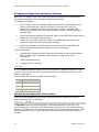
Changing configuration parameter settings
When you run oamsys, the utility starts all boards according to the configuration
parameters specified in their associated board keyword files.
To change a parameter:
•
Use of modify one of the sample board keyword files corresponding to your
country and board type. Specify the name of this new file in the File
statement in oamsys.cfg and run oamsys again. Refer to the NMS OAM
System User's Manual for information about the syntax of NMS OAM board
keyword files.
•
Specify parameter settings with oamcfg. Refer to the NMS OAM System User's
Manual for information about oamcfg.
•
Create a new board keyword file, either with additional keywords or with
keywords whose values override earlier settings.
•
Specify the settings using OAM service functions. Refer to the NMS OAM
Service Developer's Reference Manual for more information.
You can oamsys to:
•
Change which software module files are downloaded to the board at startup.
Refer to Specifying configuration file locations on page 34 for more
information.
•
Specify board switching.
•
Configure CT bus clocking.
.leo files
A .leo (loadable extensible object) file is a run module, a modular extension to the
core file. The core file and the run modules make up the software that runs on the
board's coprocessor.
The following .leo files are included with AG 2000C:
File
Description
svc.leo
DSP function manager
gtp.leo
Trunk protocol engine
voice.leo
Play and record manager
Specifying configuration file locations
Files to be downloaded to the AG boards are specified with keywords in the AG
board's keyword file. For example:
DLMFiles[0] = filename
If filename contains a path specification, NMS OAM searches for the file in the
specified directory. Otherwise, NMS OAM searches for the file in the current working
directory of ctdaemon. If the file does not exist in the current working directory, NMS
OAM searches for the file in the search path defined by the AGLOAD environment
variable.
34
Dialogic Corporation
Dialogic® AG 2000C CompactPCI Media Board Installation and Developer’s Manual
QSLAC files and trunk control programs
The QSLAC files (quad subscriber line audio - processing circuit) on an AG 2000C
board control:
•
The 2 wire impedance matching
•
Frequency response and equalization
•
Trans-hybrid balancing
Each port on the AG 2000C board can be configured separately. The configuration is
contained in a QSLAC file. Each QSLAC file is customized for a specific line interface
signaling module and for a certain country's two wire return loss requirements.
Refer to Line gain configuration on page 54 for information on controlling the gain.
Naming conventions for QSLAC files
All QSLAC files have an extension of .slc and adhere to the following naming
convention:
pp cty ss i.slc
Where...
Represents the...
For example...
pp
Two-character NMS product field.
a2 = AG 2000C board
cty
Three-character ISO country code or region
code.
ss
Two-character signaling type.
ls = loopstart
i
One character line impedance field.
6 = short 600 Ohm lines
9 = short 900 Ohm lines
n = lines longer than 2000 feet
c = complex (used in some international
markets)
For example, a2usals6.slc represents the AG 2000C board/USA/loop start/600 Ohm
line QSLAC file.
Natural Access configures the system for the QSLAC file that is intended for your
country. Do not change the configuration unless you are confident that a change is
required and is allowed by the regulatory agencies.
For more information about QSLAC files, refer to the NMS CAS for Natural Call
Control Developer's Manual.
If the default file is not used, an entry is made in the error log file at boot time. If
echo cancellation is enabled, there is no benefit in changing from the default QSLAC
file.
For example, add the following statement to the board keyword file to load a QSLAC
file:
NetworkInterface.Analog[0..23].ConfigFile = a2usals9.slc
Dialogic Corporation
35
Dialogic® AG 2000C CompactPCI Media Board Installation and Developer’s Manual
Trunk control programs
Trunk control programs (TCPs) perform all the signaling tasks necessary to interface
with the telephony protocol used on the line or trunk. TCPs are loaded onto an AG
2000C board at board initialization. After a TCP has been loaded to the AG 2000C
board, the application must start up its protocol before it can use the TCP to perform
call control on a specific port.
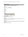
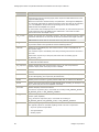
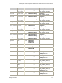
QSLAC files and TCPs for loop start
The following table lists the QSLAC files for loop start that can be selected for the
United States and Canada:
File
Description
a2usals6.slc
This is the default file that is used when you have a 600 Ohm PBX.
a2usals9.slc
Optimizes performance interfacing to a 900 Ohm PBX.
a2usalsn.slc
Optimizes performance interfacing to long lines (> 2000 feet).
Other QSLAC files are used in other parts of the world. Natural Access configures the
correct files for the countries that are supported.
For European countries that are not supported in the installation, use the a2eurlsc.slc
file when connecting to the PSTN. Refer to the NetworkInterface.Analog[x].ConfigFile
keyword for more information about QSLAC files. Refer to the NMS CAS for Natural
Call Control Developer's Manual for information on changing network tone
descriptions.
The following table lists the TCPs that are applicable to AG 2000C loop start boards:
Trunk control program
Description
nocc.tcp
No call control.
lps0.tcp
Loop start on AG 2000C.
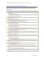
Configuring board clocking
When multiple boards are connected to the CT bus, you must set up a bus clock to
synchronize timing between them. In addition, you can configure alternative (or
fallback) clock sources to provide the clock signal if the primary source fails.
This topic describes:
•
AG 2000C clocking capabilities
•
Clock configuration methods
•
Configuring board clocking using keywords
•
Example
To create a robust clocking configuration, you must understand basic clocking
concepts such as clock mastering and fallback. This topic assumes that you have a
basic understanding of CT bus clocking. For a complete overview of CT bus clocking,
refer to the NMS OAM System User's Manual.
36
Dialogic Corporation
Dialogic® AG 2000C CompactPCI Media Board Installation and Developer’s Manual
AG 2000C clocking capabilities
This topic describes the rules and limitations that apply to setting up CT bus clocking
on AG 2000C boards.
When an AG 2000C board is configured as the system primary clock master, the
boards's first timing reference must be set to OSC. Clock fallback should be disabled.
Warning:
If there is a digital T1 or E1 board in the system, configure one of the digital boards as the
master and configure the AG 2000C board as the slave. Refer to the NMS OAM System
User's Manual for information about assessing clocking priorities in a mixed-board system.
When an AG 2000C board is configured as the system secondary clock master:
•
The board's first timing reference must be the system's primary clock master.
•
The board's fallback timing reference must be set to OSC.
When an AG 2000C board is configured as a clock slave:
•
The board's first timing reference must be the system's primary clock.
•
The board's fallback timing reference must be the system's secondary clock.
•
If there is no secondary clock master for the system, the board's fallback
timing reference must be set to OSC. In this case, if clock fallback occurs, the
board is not synchronized with the system until you reconfigure the board's
clocking.
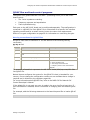
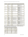
The following tables summarize the CT bus clocking capabilities of AG 2000C boards:
Note: NETREF refers to NETREF1 on the H.110 bus.
Clocking capabilities as primary master
Capability
Yes/No
Comments
Serve as primary master
Yes
Use this board as a master only if no boards with digital
trunks are present on the CT bus.
Drive A_CLOCK
Yes
Drive B_CLOCK
Yes
Available primary timing references:
Local trunk
No
Only digital trunks carry timing reference signals.
NETREF
No
This board cannot use NETREF as a timing reference.
NETREF2
No
This board does not support NETREF2.
OSC
Yes
Fallback to secondary timing
reference
No
Slave to secondary master if
both references fail
No
Dialogic Corporation
There is no timing reference to fallback to.
37
Dialogic® AG 2000C CompactPCI Media Board Installation and Developer’s Manual
Clocking capabilities as secondary master
Capability
Yes/No
Comments
Serve as secondary
master
Yes
Use this board as a master only if no boards with digital trunks are
present on the CT bus.
Drive A_CLOCK
Yes
If the primary master drives B_CLOCK, the secondary master
drives A_CLOCK.
Drive B_CLOCK
Yes
If the primary master drives A_CLOCK, the secondary master
drives B_CLOCK.
Available secondary timing references:
Local trunk
No
Only digital trunks carry timing reference signals.
NETREF
No
This board cannot use NETREF as a timing reference.
NETREF2
No
This board does not support NETREF2.
OSC
Yes
Clocking capabilities as slave
Capability
Yes/No
Serve as slave
Yes
Slave to
A_CLOCK
Yes
Slave to
B_CLOCK
Yes
Comments
Available fallback timing references:
A_CLOCK
Yes
B_CLOCK
Yes
OSC
Yes
The board is not synchronized until the application reconfigures the
clock.
Other clocking capabilities
Capability
Yes/No
Drive NETREF
Yes
Drive NETREF2
No
Operate in standalone mode
Yes
38
Comments
This board does not support NETREF2.
Dialogic Corporation
Dialogic® AG 2000C CompactPCI Media Board Installation and Developer’s Manual
Clock configuration methods
You can configure clocking in your system in one of two ways:
Method
Description
Using clockdemo
application model
Create an application that assigns each board a clocking mode, monitors
clocking changes, and reconfigures clocking when clock fallback occurs.
A sample clocking application, clockdemo, is provided with Natural Access.
clockdemo provides a robust fallback scheme that suits most system
configurations. clockdemo source code is included, allowing you to modify the
program if your clocking configuration is complex. For more information about
clockdemo, refer to the NMS OAM System User's Manual.
Note: Most clocking applications (including clockdemo) require that all boards
on the CT bus be started in standalone mode.
Using board
keywords (with or
without application
intervention)
For each board on the CT bus, set the board keywords to determine the board's
clocking mode and to determine how each board behaves if clock fallback
occurs.
This method is described in this topic. Unlike the clockdemo application, which
allows you to specify several boards to take over mastery of the clock when
another board fails, the board keyword method allows you to specify only a
single secondary clock master. For this reason, the board keyword method is
best used to implement clock fallback in your system, or in test configurations
where clock reliability is not a factor.
The board keyword method does not create an autonomous clock timing
environment. If you implement clock fallback using this method, an application
must still intervene when clock fallback occurs to reset system clocking before
other clocking changes occur. If both the primary and secondary clock masters
stop driving the clocks, and an application does not intervene, the boards
default to standalone mode.
Choose only one of these configuration methods across all boards on the CT bus.
Otherwise, the two methods can interfere with one another and board clocking may
not operate properly.
Configuring AG 2000C boards using board keywords
AG 2000C board keywords enable you to configure the board in the following ways:
•
System primary clock master
•
System secondary clock master
•
Clock slave
•
Standalone mode
You can also use board keywords to establish clock fallback sources.
The following sections describe how to use board keywords to specify the clocking
role of each AG 2000C board in a system.
Dialogic Corporation
39
Dialogic® AG 2000C CompactPCI Media Board Installation and Developer’s Manual
Primary clock master
Use the following board keywords to configure an AG 2000C board as a primary clock
master:
Keyword
Description
Clocking.HBus.ClockMode
Specifies the CT bus clock that the board drives. This keyword must
reference either A clock (MASTER_A) or B clock (MASTER_B).
Clocking.HBus.ClockSource
Specifies the source from which this board derives its timing. Set this
keyword to OSC.
Clocking.HBus.AutoFallBack
Set this keyword to NO.
Note: If the primary master's first source fails and then returns, the board's timing
reference (and consequently, the references for any slaves) switches back to the first
timing source. This is not true for the secondary timing master.
Secondary clock master
Use the following board keywords to configure an AG 2000C board as a secondary
clock master:
Keyword
Description
Clocking.HBus.ClockMode
Specifies the CT bus clock that the secondary master drives. This
keyword must reference the clock (MASTER_A or MASTER_B) not
driven by the primary clock master.
Clocking.HBus.ClockSource
Specifies the source from which this board derives its timing. Set
this keyword to the clocks driven by the primary clock master. For
example, if the primary master drives A clock, set this keyword to
A_CLOCK.
Clocking.HBus.AutoFallBack
Enables or disables clock fallback on the board. Set this keyword to
YES.
Clocking.HBus.FallBackClockSource
Specifies the alternate timing reference to use when the master
clock does not function properly. Set this keyword to OSC.
Note: If the primary master's timing reference recovers, the secondary master
continues to drive the clock referenced by all clock slaves in the system until the
application intervenes.
Clock slave
Use the following board keywords to configure an AG 2000C board as a clock slave:
Keyword
Description
Clocking.HBus.ClockMode
Specifies the CT bus clock from which the board derives its timing.
Set this keyword to SLAVE to indicate that the board does not drive
any CT bus clock.
Clocking.HBus.ClockSource
Specifies the source from which this clock derives its timing. Set
this keyword to reference the clock driven by the primary clock
master.
Clocking.HBus.AutoFallBack
Enables or disables clock fallback on the board.
Clocking.HBus.FallBackClockSource
Specifies the alternate clock reference to use when the master
clock does not function properly. For clock slaves, set this keyword
to reference the clock (A_CLOCK or B_CLOCK) driven by the
secondary clock master.
40
Dialogic Corporation
Dialogic® AG 2000C CompactPCI Media Board Installation and Developer’s Manual
Standalone mode
To configure an AG 2000C board in standalone mode so the board references its own
clocking information, set Clocking.HBus.ClockMode to STANDALONE and set
Clocking.HBus.ClockSource to OSC. The board then uses its own oscillator as a
timing signal reference. The board cannot make switch connections to the CT bus.
Multiple board system example
The following example assumes a system configuration where three AG 2000C
boards reside in a single chassis. The boards are configured in the following way
using board keywords:
Board
Configuration
Board 0
System primary bus master (driving the A clock)
Board 1
System secondary bus master (driving the B clock)
Board 2
Clock slave (clock fallback enabled)
This configuration assigns the following clocking priorities:
Priority
Timing reference
First
Board 0, local oscillator
Second
Board 1, local oscillator
The following illustration shows a multiple-board system with a primary and
secondary clock master:
CT bus
A_CLOCK
B_CLOCK
NETREF
A_CLOCK
B_CLOCK
NETREF
Board 0
Primary
clock
master
Drives A_CLOCK
from local oscillator
Board 1
Secondary
clock
master
Board 2
Clock slave
Drives B_CLOCK,
references A_CLOCK
(falls back to local
oscillator)
References A_CLOCK
(falls back to B_CLOCK)
Driving clock
Clock source
Clock fallback source
Sample board clocking configuration
Dialogic Corporation
41
Dialogic® AG 2000C CompactPCI Media Board Installation and Developer’s Manual
The following table shows board keywords used to configure the boards according to
the configuration shown in the preceding illustration:
Board
Role
Clocking keyword settings
0
Primary clock master
Clocking.HBus.ClockMode = MASTER_A
Clocking.HBus.ClockSource = OSC
Clocking.HBus.AutoFallBack = NO
1
Secondary clock master
Clocking.HBus.ClockMode = MASTER_B
Clocking.HBus.ClockSource = A_CLOCK
Clocking.HBus.AutoFallBack = YES
Clocking.HBus.FallBackClockSource = OSC
2
Clock slave
Clocking.HBus.ClockMode = SLAVE
Clocking.HBus.ClockSource = A_CLOCK
Clocking.HBus.AutoFallBack = YES
Clocking.HBus.FallBackClockSource = B_CLOCK
In this configuration, Board 0 is the primary clock master and drives A_CLOCK. All
slave boards on the system use the A clock as their first timing reference. Board 0
references its timing from its local oscillator.
If the clocking signal used by Board 0 fails, then Board 0 stops driving A_CLOCK. The
secondary clock master (Board 1) then falls back to a timing reference based on its
local oscillator and uses this signal to drive B_CLOCK. B_CLOCK then becomes the
timing source for all boards that use B_CLOCK as their backup timing reference.
Note: For this clock fallback scheme to work, all clock slaves must specify A_CLOCK
as the clock source and B_CLOCK as the clock fallback source.
Enabling echo cancellation
Echo cancellation improves the input signal-to-noise ratio during play which improves
the performance of operations such as tone detection and speech recognition.
To enable echo cancellation:
Step
Action
1
Include the following statement in the board keyword file:
DSP.C5x[x].Files = echo.m54
where x = the next available index.
2
Set the appropriate ADI service parameters in your application and in your system.
Refer to the ADI Service Developer's Reference Manual for information about
configuring echo cancellation on the AG 2000C board.
42
Dialogic Corporation
6
Verifying the installation
Status indicator LEDs
The AG 2000C board has indicators (LEDs) on the end bracket of the board as shown
in the following illustration:
CompactPCI
R
DIAG
HBAT
LBAT
TM
NMS
Hot Swap
LEDs on the end bracket
The following table describes each of the LEDs:
LED
Description
DIAG
The LED is on after the board is booted.
HBAT
LED on verifies -48 V DC is available to the board from the external power supply (for future
use).
LBAT
LED on verifies -30 V DC is available to the board from the external power supply (for future
use).
Dialogic® AG 2000C CompactPCI Media Board Installation and Developer’s Manual
LED
Description
Hot
Swap
Illuminates when it is safe to remove the AG 2000C board from the system. The LED
illuminates under one of the following conditions:
If the board is fully inserted when the backplane is powered up, the blue LED
momentarily flashes. This is a normal part of the initialization process.
• After opening the handles (during the extraction process), the LED illuminates to
indicate that it is safe to remove the board. Do not remove the board until the LED
illuminates. This occurs only if Hot Swap software is present.
• If the LED remains illuminated during insertion of a board, the board failed to
successfully perform its primary hardware initialization. While it is safe to remove the
board, this condition indicates a problem.
For more information about Hot Swap, refer to the NMS OAM System User's Manual.
•
Verifying board installation
Complete the following steps to verify that the board is installed correctly:
Step
Action
1
Create a board keyword file to boot an AG 2000C board by copying or editing one of the sample
board keyword files to match your specific configuration. Refer to Configuring and starting the
system with oamsys on page 30 for more information. For example, use the agpi2000c.cfg file
to configure the board for the loop start protocol.
2
Run oammon to monitor the status of all boards.
3
Use pciscan to determine the bus and slot number. For more information about pciscan, refer
to the NMS OAM System User's Manual.
4
Edit the oamsys.cfg file to reflect the board locations in your system.
5
Boot the board using the command:
oamsys
Retrieving AG board configuration information: boardinf
boardinf is a program that reports the board number, address, type, number of
ports, memory, and DSP timeslot assignments for each AG board in a system.
boardinf opens the AG driver and retrieves the configuration information for up to 16
AG 2000C boards. If an AG 2000C board exists and is properly initialized, its
configuration is displayed and its DSP port addresses are displayed as one or more
timeslot ranges.
To run boardinf:
Step
Action
1
Ensure that the AG 2000C boards were initialized.
2
Open a command window.
3
Enter the following command:
boardinf
boardinf displays the configuration information for each AG 2000C board in the system that has
been loaded and initialized.
4
44
If no boards are detected, verify that the AG 2000C board(s) is loaded and initialized and
repeat the command. If the AG 2000C configuration information is not as expected, review the
board keyword file.
Dialogic Corporation
Dialogic® AG 2000C CompactPCI Media Board Installation and Developer’s Manual
Interactive test program: ctatest
ctatest is a menu-driven interactive program. Enter one- and two-letter commands
to execute Natural Access and ADI service functions. Some commands prompt the
user for additional input. For example, running a tone generator requires the user to
specify frequencies and amplitudes. For more information about ctatest, refer to the
Natural Access Developer's Reference Manual.
ctatest can execute more than one asynchronous function concurrently. For example,
you can run a tone detector (ET) and record voice (RF) simultaneously. You can abort
any function by entering the respective stop command (DT and RS for tone and
record).
If Clocking.HBus.ClockMode = STANDALONE, then default local connections between
the DSP resources and the line interfaces are nailed up as described in Default
connections on page 51.
To experiment with output and input functions simultaneously, execute two instances
of ctatest. Use the swish MakeConnection command to make quad connections
between two ports, one bound to each ctatest instance. Refer to the Switching
Service Developer's Reference Manual for information about swish.
For example, to interactively experiment with tone generation and detection, start a
tone detector in the first ctatest instance and a tone generator in the second ctatest
instance.
Using swish for a standalone board
No default connections are made for a standalone board if CT bus connectivity is
enabled in the board keyword file. Use swish to connect the local network interface
to the local DSP resource. You can use swish interactively, or create a script in a flat
text file.
The following example of swish commands nails up the voice and signaling streams
for all 24 line interfaces of an AG 2000C board that has been configured as board 0.
openswitch ag2000C = agsw 0
resetswitch ag2000C
# make voice and signaling connections
makeconnection ag2000C local:0:0..23 to local:5:0..23 QUAD
closeswitch ag2000C
exit
Dialogic Corporation
45
Dialogic® AG 2000C CompactPCI Media Board Installation and Developer’s Manual
Using ctatest with an AG 2000C loop start board
Connect a loop start line from a PBX or the public network as a test line to your
system so you can call the test line from a telephone connected to another line.
To use ctatest:
Step
Action
1
Make sure that the board keyword file includes the following statement for the board that you
will be using:
TCPFiles[x] = lps0.tcp
where x = the next available index.
If necessary, edit the board keyword file.
2
Start ctatest.
The initial ctatest menu appears.
3
Enter OP to create a context and open the ADI service.
CTAEVN_OPEN_SERVICES_DONE is displayed on your screen.
4
Start a protocol by entering SP.
The following message appears:
Enter protocol name ['nocc']:
Enter the loop start protocol: lps0.
The following message appears:
Event: NCCEVN_START_PROTOCOL_DONE, CTA_REASON_FINISHED
5
Place a call to the line connected to the AG 2000C board.
The following message appears:
Event: NCCEVN_INCOMING_CALL
6
Initiate answering the call by entering AC.
The following message appears:
Number of rings [1]:
7
Press Enter.
You should hear a single ring tone.
The following messages appear:
Event: NCCEVN_ANSWERING_CALL
Event: NCCEVN_CALL_CONNECTED, NCC_CON_ANSWERED
8
Begin recording to memory by entering RM.
You should hear a beep on the handset.
9
Say "Hello World," and wait.
The following message appears on the screen (you may see a different number of bytes):
Event: VCEEVN_RECORD_DONE, Voice End, msec=3820.
10
Play back your voice by entering PM.
You should hear "Hello World," and ctatest displays:
Event: VCEEVN_PLAY_DONE, Finished, msec=3820.
11
46
Quit the test program by entering Q.
Dialogic Corporation
Dialogic® AG 2000C CompactPCI Media Board Installation and Developer’s Manual
Demonstration programs
The following demonstration programs are provided with Natural Access and can be
used to verify that the AG 2000C board is operating correctly:
Program
Demonstrates...
ctatest
Natural Access functions.
incta
Handling inbound calls.
outcta
Establishing outbound calls.
prt2prt
Transferring calls from an incoming line to an outgoing line and using the Switching service
to make connections and to send patterns.
vceplay
Using the Voice Message service to play messages in voice files.
vcerec
Recording one or more messages to a voice file.
Note: Executables for incta, outcta, and prt2prt are in the respective sub-directories
under \nms\ctaccess\demos.
To run these demonstration programs on the AG 2000C board, specify the slot
number of the local DSP resource on which to run the program. If
Clocking.HBus.ClockMode = STANDALONE, then default switching connections
between the on-board DSP resources and signaling modules are initialized as
described in Default connections on page 51.
To run ctatest on DSP port 0, enter:
ctatest -s0
To run ctatest on DSP port 2, enter:
ctatest -s2
Switching connections must be made between DSP resources and signaling modules
using the Natural Access Switching service or the swish utility. Refer to the AG
2000C switching section for more information.
Refer to the Natural Access Developer's Reference Manual for details about Natural
Access demonstration programs.
Dialogic Corporation
47
7
AG 2000C switching
AG 2000C switch model
This topic describes:
•
The specific use of each stream, as shown for H.110 streams and local
streams
•
An illustration of the AG 2000C switch model
•
Lucent T8100A switch blocking
H.110 streams
H.110 streams
H.110 bus
Streams clocked at 8 MHz: timeslots 0..127 for all 32 streams
Local streams
Local stream
Line interface voice in and out
Streams 0 and 1, timeslot 0..7, 0..15, or 0..23
Line interface signaling in and out
Streams 2 and 3, timeslot 0..7, 0..15, or 0..23
DSP voice in and out
Streams 4 and 5, timeslot 0..7, 0..15, or 0..23
DSP signaling in and out
Streams 6 and 7, timeslot 0..7, 0..15, or 0..23
Dialogic® AG 2000C CompactPCI Media Board Installation and Developer’s Manual
Switch model
The following illustration shows the AG 2000C switch model:
CT D0..31
H . 110 bus
0
1
2
3
4
5
6
7
8
9
10
11
12
H.110 bus
.
.
.
24
25
26
27
28
29
30
31
0
2
4
6
Local
bus
Signaling
Voice
DSP
resources
Signaling
Analog
line
interfaces
Voice
0
1
2
3
4
5
6
7
8
9
10
11
. 12
.
.
24
25
26
27
28
29
30
31
1
3
5
7
Signaling
Voice
Signaling
Voice
Local
devices
AG 2000C switch model
Lucent T8100A switch blocking
Switching on the AG 2000C board is implemented by the Lucent T8100A chip
(HMIC). The Lucent T8100A chip can perform local bus to local bus switching in full
non-blocking fashion.
The number of H.110 connections is limited to a maximum of 128 full duplex or 256
simplex (or half-duplex) connections, in any combination, from either:
•
H.110 bus to the local bus, or
•
H.110 bus to H.110 bus
There are no restrictions on local switching. Any local device can be connected to any
other local device.
50
Dialogic Corporation
Dialogic® AG 2000C CompactPCI Media Board Installation and Developer’s Manual
Signaling modules and logical timeslots
On AG 2000C boards, each signaling module is hardwired to a specific logical
timeslot on the local bus. Each signaling module supports four ports of telephone
network connectivity and is permanently connected to four pairs in the RJ-21
connector. Each pair is therefore bound to a corresponding timeslot on the local bus.
The following illustration shows the relationship between signaling modules,
timeslots, and the connector for AG 2000C boards:
Rear I/O transition board
AG 2000C board
Timeslots
4..7
Timeslots
12..15
Timeslots
16..19
RJ-21 connector
Timeslots
0..3
Timeslots
8..11
Timeslots
20..23
Logical timeslots, signaling modules, and RJ-21 connector
Default connections
Refer to the following table to determine how default connections occur on the AG
2000C board:
If Clocking.HBus.ClockMode =
STANDALONE
SLAVE
MASTER_A/MASTER_B
Yes
Yes
Yes
Yes
No
No
No
No
Auto
Yes
No
No
If SwitchConnections =
If SwitchConnections = Yes, default connections are made regardless of the
Clocking.HBus.ClockMode setting.
If SwitchConnections = No, default connections are not made regardless of the
Clocking.HBus.ClockMode setting.
If SwitchConnections = Auto and Clocking.HBus.ClockMode = STANDALONE, default
connections are made.
Dialogic Corporation
51
Dialogic® AG 2000C CompactPCI Media Board Installation and Developer’s Manual
If SwitchConnections = Auto and Clocking.HBus.ClockMode = SLAVE, MASTER_A, or
MASTER_B, default connections are not made.
The following default local connections are nailed up at board initialization:
Switch connection
MVIP-95
Full duplex connection between line interface voice information and DSP
resources.
local:0:0..23 =>
local:5:0..23
local:4:0..23 =>
local:1:0..23
Full duplex connection between line interface signaling information and
DSP resources.
local:2:0..23 =>
local:7:0..23
local:6:0..23 =>
local:3:0..23
You can control switching using the Natural Access Switching service. Refer to the
Switching Service Developer's Reference Manual for more information.
52
Dialogic Corporation
8
Configuration parameters
Using the Switching service
Local device configuration on the AG 2000C board is controlled by the Switching
service. The Switching service provides functions for accessing device configuration
parameters defined by the underlying hardware and device driver.
swiConfigLocalTimeslot and swiGetLocalTimeslotInfo enable applications to
configure a device on a given local stream and timeslot by specifying a particular
parameter and providing a data structure specific to that parameter. The prototypes
for these functions are repeated here for convenience.
For more information about the Switching service, refer to the Switching Service
Developer's Reference Manual.
Function information
The syntax of swiConfigLocalTimeslot and swiGetLocalTimeslotInfo is:
Prototype
DWORD swiConfigLocalTimeslot (SWIHD swihd, SWI_LOCALTIMESLOT_ARGS
*args, void *buffer, unsigned size)
DWORD swiGetLocalTimeslotInfo ( SWIHD swihd, SWI_LOCALTIMESLOT_ARGS
*args, void *buffer, unsigned size)
Argument
Description
swihd
Switch handle returned by swiOpenSwitch.
args
Pointer to a SWI_LOCALTIMESLOT_ARGS structure. This structure indicates the specific
parameter to be configured on the device indicated by localstream and localtimeslot.
typedef struct
{
DWORD localstream;
DWORD localtimeslot;
DWORD deviceid;
DWORD parameterid;
} SWI_LOCALTIMESLOT_ARGS;
buffer
Pointer to a structure that is specific to the parameterid.
size
Size of buffer, in bytes.
Return Values
SUCCESS, or an error code from ctaerr.h or swidef.h.
Details
Applications using swiConfigLocalTimeslot and swiGetLocalTimeslotInfo must
open the Switching service. Refer to the Natural Access Developer's Reference
Manual for more information about opening services.
Dialogic® AG 2000C CompactPCI Media Board Installation and Developer’s Manual
Line gain configuration
The AG 2000C supports input and output gain configuration on network voice ports
(timeslots) from -6 dB to +6 dB in one dB increments.
Input gain is applied to the signal received from the network. Output gain is applied
to the signal transmitted to the network. The default value for both input line gain
and output line gain on the AG 2000C loop start board is nominal 0 dB.
This topic describes:
•
Getting the line gain
•
Setting the line gain
Caution:
Increasing gain can also increase noise, echo, and possibly cause oscillations on the
telephone network. There also may be regulatory authority implications. Use gain with
caution.
Decreasing gain may reduce echo and other noise.
Getting the line gain
Use swiGetLocalTimeslotInfo to query the input or output line gain. Set the
arguments for this function as follows:
Argument
Field
swihd
args
Value
Handle returned by swiOpenSwitch.
localstream
0 or 1. Refer to the AG 2000C switch model on page 49.
localtimeslot
0..23. Refer to the AG 2000C switch model on page 49.
deviceid
MVIP95_ANALOG_LINE_DEVICE
parameterid
MVIP95_INPUT_GAIN or MVIP95_OUTPUT_GAIN
buffer
Points to the NMS_LINE_GAIN_PARMS structure.
size
Size of buffer, in bytes.
The NMS_LINE_GAIN_PARMS structure is:
typedef struct
{
INT32 gain;
} NMS_LINE_GAIN_PARMS;
The value returned in the gain component of NMS_LINE_GAIN_PARMS represents
the gain in dB multiplied by 1000. For example, if the input gain on a particular
network timeslot is currently set to -3 dB, after calling swiGetLocalTimeslotInfo
for parameter MVIP95_INPUT_GAIN, the gain field is -3000.
54
Dialogic Corporation
Dialogic® AG 2000C CompactPCI Media Board Installation and Developer’s Manual
The following sample code shows how to retrieve line gain applied to a signal
received from the network:
#include "swidef.h"
#include "mvip95.h"
#include "nmshw.h"
/*
/*
/*
CT Access Switching service
MVIP-95 definitions
NMS hardware-specific definitions
*/
*/
*/
DWORD myGetReceiveGain ( SWIHD swihd, SWI_TERMINUS terminus, INT32* gain_dB )
{
SWI_LOCALTIMESLOT_ARGS args;
NMS_LINE_GAIN_PARMS
device ;
DWORD
rc ;
args.localstream
args.localtimeslot
args.deviceid
args.parameterid
=
=
=
=
terminus.stream ;
terminus.timeslot ;
MVIP95_ANALOG_LINE_DEVICE ;
MVIP95_INPUT_GAIN ;
rc = swiGetLocalTimeslotInfo(
/* CT Access switch handle
/* target device and config item
/* buffer (defined by parameterid)
/* buffer size in bytes
*gain_dB
=
device.gain / 1000
*/ swihd,
*/ & args,
*/(void*) & device,
*/ sizeof(device));
;
return rc ;
}
The following sample code shows how to retrieve line gain applied to a signal
transmitted to the network:
#include "swidef.h"
#include "mvip95.h"
#include "nmshw.h"
/*
/*
/*
CT Access Switching service
*/
MVIP-95 definitions
*/
NMS hardware-specific definitions */
DWORD myGetTransmitGain ( SWIHD swihd, SWI_TERMINUS terminus, INT32* gain_dB )
{
SWI_LOCALTIMESLOT_ARGS args ;
NMS_LINE_GAIN_PARMS
device ;
DWORD
rc ;
args.localstream
args.localtimeslot
args.deviceid
args.parameterid
=
=
=
=
terminus.stream ;
terminus.timeslot ;
MVIP95_ANALOG_LINE_DEVICE ;
MVIP95_OUTPUT_GAIN ;
rc = swiGetLocalTimeslotInfo(
/* CT Access switch handle
/* target device and config item
/* buffer (defined by parameterid)
/* buffer size in bytes
*gain_dB
=
device.gain / 1000
*/
*/
*/
*/
swihd,
& args,
(void*) & device,
sizeof(device));
;
return rc ;
}
Dialogic Corporation
55
Dialogic® AG 2000C CompactPCI Media Board Installation and Developer’s Manual
Setting the line gain
Use swiConfigLocalTimeslot to set the the input or output line gain. Set the
arguments for this function as follows:
Argument
Field
Value
swihd
args
Handle returned by swiOpenSwitch.
localstream
0 or 1. Refer to the AG 2000C switch model on page 49.
localtimeslot
0..23. Refer to the AG 2000C switch model on page 49.
deviceid
MVIP95_ANALOG_LINE_DEVICE
parameterid
MVIP95_INPUT_GAIN or MVIP95_OUTPUT_GAIN
buffer
Points to the NMS_LINE_GAIN_PARMS structure.
size
Size of buffer, in bytes.
The NMS_LINE_GAIN_PARMS structure is:
typedef struct
{
INT32 gain;
} NMS_LINE_GAIN_PARMS;
Multiply the desired gain setting in dB by 1000. For example, to set the input line
gain on a network voice port to -4 dB, set the gain field of NMS_LINE_GAIN_PARMS
to -4000.
The following sample code shows how to configure gain applied to a signal received
from the network:
#include "swidef.h"
#include "mvip95.h"
#include "nmshw.h"
/*
/*
/*
CT Access Switching service
*/
MVIP-95 definitions
*/
NMS hardware-specific definitions */
DWORD mySetReceiveGain ( SWIHD swihd, SWI_TERMINUS terminus, INT32 gain_dB )
{
SWI_LOCALTIMESLOT_ARGS args;
NMS_LINE_GAIN_PARMS
device ;
args.localstream
args.localtimeslot
args.deviceid
args.parameterid
device.gain
=
=
=
=
=
terminus.stream ;
terminus.timeslot ;
MVIP95_ANALOG_LINE_DEVICE ;
MVIP95_INPUT_GAIN ;
gain_dB * 1000
;
return swiConfigLocalTimeslot (
/* CT Access switch handle
/* target device and config item
/* buffer (defined by parameterid)
/* buffer size in bytes
*/
*/
*/
*/
swihd,
& args,
(void*) & device,
sizeof(device));
}
56
Dialogic Corporation
Dialogic® AG 2000C CompactPCI Media Board Installation and Developer’s Manual
The following sample code shows how to configure line gain applied to a signal
transmitted to the network:
#include "swidef.h" /* CT Access Switching service
*/
#include "mvip95.h" /* MVIP-95 definitions
*/
#include "nmshw.h"
/* NMS hardware-specific definitions */
*/
DWORD mySetTransmitGain ( SWIHD swihd, SWI_TERMINUS terminus, INT32 gain_dB )
{
SWI_LOCALTIMESLOT_ARGS args;
NMS_LINE_GAIN_PARMS
device ;
args.localstream
args.localtimeslot
args.deviceid
args.parameterid
device.gain
=
=
=
=
=
terminus.stream ;
terminus.timeslot ;
MVIP95_ANALOG_LINE_DEVICE ;
MVIP95_OUTPUT_GAIN ;
gain_dB * 1000
;
return swiConfigLocalTimeslot (
/* CT Access switch handle
/* target device and config item
/* buffer (defined by parameterid)
/* buffer size in bytes
*/
*/
*/
*/
swihd,
& args,
(void*) & device,
sizeof(device));
}
Dialogic Corporation
57
9
Keyword summary
Using keywords
The keywords for an AG 2000C board describe that board's configuration. Some
keywords are read/write; others are read-only:
Keyword type
Description
Read/write
(editable)
Determines how the board is configured when it starts up. Changes to these
keywords become effective after the board is rebooted.
Read-only
(informational)
Indicates the board's current configuration. Read-only keywords cannot be
modified.
This topic describes:
•
Setting keyword values
•
Retrieving keyword values
Note: To learn how to use NMS OAM utilities such as oamsys and oamcfg, refer to
the NMS OAM System User's Manual. To learn about setting and retrieving keywords
using OAM service functions, refer to the NMS OAM Service Developer's Reference
Manual.
AG plug-in keywords exist in a separate record in the NMS OAM database. They
indicate certain board family-level information.
A keyword has the general syntax:
keyword = value
Keywords are not case sensitive except where operating system conventions prevail
(for example, file names under UNIX). All values are strings, or strings that
represent integers. An integer keyword can have a fixed numeric range of legal
values. A string keyword can support a fixed set of legal values, or can accept any
string.
Dialogic® AG 2000C CompactPCI Media Board Installation and Developer’s Manual
Setting keyword values
There are several ways to set the values of read/write keywords:
•
Use or modify one of the sample board keyword files corresponding to your
country and board type. Specify the name of this new file in the File
statement in oamsys.cfg, and run oamsys again. Refer to the NMS OAM
System User's Manual for information about the syntax of board keyword
files.
Note: Using oamsys reboots all boards in the system.
•
Create a new board keyword file, either with additional keywords or keywords
whose values override earlier settings.
•
Specify parameter settings using the oamcfg utility. Refer to the NMS OAM
System User's Manual for information about oamcfg.
•
Specify the settings using OAM service functions. Refer to the NMS OAM
Service Developer's Reference Manual for more information.
To set board keywords, specify the board name in the system configuration file or on
the oamcfg command line. To set AG plug-in level keywords, specify the AG plug-in
name (agplugin.bpi).
Note: Keyword values take effect after the board is rebooted.
Retrieving keyword values
To retrieve the values of read/write and read-only keywords:
•
Run the oaminfo sample program. On the command line, specify the board
using either its name (with the -n option) or number (with the -b option):
oaminfo -n boardname
oaminfo -b boardnum
To access AG plug-in level keywords, specify the AG plug-in name on the
command line:
oaminfo -n agplugin.bpi
oaminfo returns a complete list of keywords and values. For more information
about oaminfo, refer to the NMS OAM Service Developer's Reference Manual.
•
60
Use the OAM service. Refer to the NMS OAM Service Developer's Reference
Manual for more information.
Dialogic Corporation
Dialogic® AG 2000C CompactPCI Media Board Installation and Developer’s Manual
Editable keywords
The following table summarizes the keywords that you can change:
If you want to...
Use these keywords...
Specify whether the board is started or stopped
automatically
AutoStart
AutoStop
Specify the board location
Location.PCI.Bus (set in the oamsys.cfg
file)
Location.PCI.Slot (set in the oamsys.cfg
file)
Specify information about the board
LoadFile
LoadSize
Name (set in the oamsys.cfg file)
Number (set in the oamsys.cfg file)
DLMFiles[x]
RunFile
TCPFiles[x]
Change the QSLAC file
NetworkInterface.Analog[x].ConfigFile
Set up test level information
BootDiagnosticLevel
Modify memory allocation
Buffers[x].Num
Buffers[x].Size
MaxChannels
Set up clocking information
Clocking.HBus.ClockMode
Clocking.HBus.ClockSource
Clocking.HBus.Segment
Configure clock automatic fallback
Clocking.HBus.AutoFallBack
Clocking.HBus.FallBackClockSource
Set up information specific to NETREF
Clocking.HBus.NetRefSource
Clocking.HBus.NetRefSpeed
Set up switching information
SwitchConnections
SwitchConnectMode
Control switching on the echo canceller reference stream
Echo.AutoSwitchingRefSource
Echo.EnableExternalPins
Configure DSPs
DSP.C5x[x].Image
DSP.C5x.Lib
DSP.C5x.Loader
DSP.C5x[x].Os
DSP.C5x[x].Files[y]
SignalIdleCode
VoiceIdleCode
Xlaw
Dialogic Corporation
61
Dialogic® AG 2000C CompactPCI Media Board Installation and Developer’s Manual
Informational keywords
You cannot edit the keywords listed in this topic. Use these keywords for retrieving
information about the:
•
Board
•
EEPROM
•
Board driver
Retrieving board information
Keyword
Type
Description
Location.Type
String
Host system's bus type.
Product
String
At the board level, the product type of the board.
State
String
State of the physical board. Expected values are IDLE, BOOTED, or
TESTING.
Retrieving EEPROM information
Keyword
Type
Description
Eeprom.AssemblyRevision
Integer
Hardware assembly level.
Eeprom.BoardSpecific
Integer
Board-specific data.
Eeprom.BusClkDiv
Integer
Bus speed is equal to 2 x CPU speed busclkdiv.
Eeprom.CheckSum
Integer
EEPROM checksum.
Eeprom.CPUSpeed
Integer
Coprocessor speed in MHz.
Eeprom.DRAMSize
Integer
DRAM size in kilobytes.
EEprom.DSPSpeed
Integer
DSP processor speed in MHz.
EEprom.Family
Integer
Board family.
Eeprom.MFGWeek
Integer
Week of the last full test.
Eeprom.MFGYear
Integer
Year of the last full test.
Eeprom.MSBusType
Integer
Media stream bus type. H.110 = 1
Eeprom.NumDSPCores
Integer
Total number of DSP cores on the motherboard.
Eeprom.SerialNum
Integer
Serial number unique to each board. This number is
factory configured.
Eeprom.SoftwareCompatibility
Integer
Minimum software revision level.
Eeprom.SRAMSize
Integer
SRAM size in kilobytes.
Eeprom.SubType
Integer
AG family variant information.
62
Dialogic Corporation
Dialogic® AG 2000C CompactPCI Media Board Installation and Developer’s Manual
Retrieving board driver information
Keyword
Type
Description
Driver.BoardID
String
Board driver ID for the current board. Each board accessed by a driver
has a unique ID. However, two boards accessed by different drivers
can have the same driver ID number.
Driver.Name
String
Operating system independent root name of the driver, for example,
ag.
SwitchDriver.Name
String
Operating system independent root name of the switching driver.
Expected value is AGSW.
Plug-in keywords
The AG plug-in keywords are:
•
Boards[x]
•
LoadSize
•
Products[x]
•
Version.Major
•
Version.Minor
Dialogic Corporation
63
10
Keyword reference
Using the keyword reference
The keywords are presented in detail in the following topics. Each keyword
description includes:
Syntax
The syntax of the keyword
Access
Read/write or read-only
Type
The data type of the value: string, integer, or file name
Default
Default value
Allowed values
A list of all possible values
Example
An example of usage
Details
A detailed description of the keyword's function
See also
A list of related keywords
Dialogic® AG 2000C CompactPCI Media Board Installation and Developer’s Manual
AutoStart
Specifies whether the board automatically starts when ctdaemon is started or the
board is Hot Swap inserted.
Syntax
AutoStart = setting
Access
Read/Write
Type
String
Default
NO
Allowed values
YES | NO
Example
AutoStart = NO
Details
The Supervisor keyword AutoStartEnabled enables or disables the autostart feature.
If AutoStartEnabled is set to YES, the Supervisor starts each board whose AutoStart
keyword is set to YES when ctdaemon is started. If AutoStartEnabled is set to NO, no
boards are started automatically, regardless of the setting of the AutoStart keyword.
For more information, refer to the NMS OAM System User's Manual.
See also
AutoStop
66
Dialogic Corporation
Dialogic® AG 2000C CompactPCI Media Board Installation and Developer’s Manual
AutoStop
Specifies whether the board automatically stops when ctdaemon is stopped.
Syntax
AutoStop = setting
Access
Read/Write
Type
String
Default
NO
Allowed values
YES | NO
Example
AutoStop = NO
Details
The Supervisor keyword AutoStopEnabled enables or disables the autostop feature.
If AutoStopEnabled is set to YES, the Supervisor stops each board whose AutoStop
keyword is set to YES when ctdaemon is stopped. If AutoStopEnabled is set to NO,
no boards are stopped automatically, regardless of the setting of the AutoStop
keyword.
For more information, refer to the NMS OAM System User's Manual.
See also
AutoStart
Dialogic Corporation
67
Dialogic® AG 2000C CompactPCI Media Board Installation and Developer’s Manual
Boards[x]
Specifies the name of the board object that is managed by the AG plug-in.
Syntax
Boards[x] = boardname
x = the index of the Board array keyword.
Access
Read-only (AG plug-in level)
Type
String
Allowed values
Any board name.
See also
Name, Number
68
Dialogic Corporation
Dialogic® AG 2000C CompactPCI Media Board Installation and Developer’s Manual
BootDiagnosticLevel
Specifies the level of diagnostics during initialization of the board.
Syntax
BootDiagnosticLevel = level
Access
Read/Write
Type
Integer
Default
2
Allowed values
0|1|2|3
Example
BootDiagnosticLevel = 2
Details
This value takes precedence over the corresponding value of the BootDiagnosticLevel
keyword set in the system configuration file.
The valid values for level are 0, 1, 2, and 3. Zero (0) indicates that no diagnostics
are performed, and 3 is the maximum level. The trade-off for higher levels of
diagnostics is the increased time needed to initialize each AG board at load time.
If a test fails, the test number is reported back as the error code. Some tests can
pass back more than one error code depending on the options selected, the mode of
failure, or both. Some tests report additional information.
Dialogic Corporation
69
Dialogic® AG 2000C CompactPCI Media Board Installation and Developer’s Manual
The following tests are performed during the boot diagnostics:
Test
number
Description
1
Coprocessor booted by writing 11h to
SRAM base address.
Error
code
•
Coprocessor never booted at all.
1
•
Coprocessor booted but crashed after
writing to SRAM base address.
11h
•
aaaah option switch selected and
coprocessor crashed after updating
SRAM base address.
aaaah
#
WDS
2
Verifies the board type.
2
1
3
Checks the DRAM size and BUSCLK
programmed in the EEPROM, and sets up
the part accordingly if valid EEPROM
choice.
3
1
4
Tests DSP control and status registers.
4
2
6
Tests DRAM.
6
4
7
Tests DSPs.
7
5
8
Serial port test.
8
2
•
9
12
70
Failed internal loopback test. Wrote a
49h and received something else
back.
HMIC tests
Error number
Refer to the following
tables for an explanation
of the error number.
•
Failed I/O test.
9
5
1
•
Failed register test.
9
5
1
•
Failed CAM test.
9
5
2
•
Failed local connections test.
9
5
3
12
4
DSP HPI tests.
Dialogic Corporation
Dialogic® AG 2000C CompactPCI Media Board Installation and Developer’s Manual
The following information is reported back to the host when there is a diagnostic
failure:
Error
code
WORD1
#
WDS
WORD2
WORD3
WORD4
WORD5
Additional data
1
None
2
1
EEPROM board
type
3
1
EEPROM DRAM
size word
4
2
written
read (masked
by 0xfh)
6
4
address lo
address hi
written
read
7
5
# DSPs booted
Number
expected
test ID
memory failed
address
8
2
written
read
9
5
See the following table for more information.
12
4
00 = HPIA test
DSP number
Written
contents of
failed address
Read
01 = HPI
memory test
The following information is reported back to the host for error code 9 when there is
a diagnostic failure:
# WDS
HMIC ID
Error number
Address
Write
Read
5
0
1
5aa5
Write
Read
5
0
1
Register number
Write
Read
5
0
2
CAM address
Write
Read
5
0
3
Local connections address
Write
Read
Dialogic Corporation
71
Dialogic® AG 2000C CompactPCI Media Board Installation and Developer’s Manual
Buffers[x].Num
Specifies the number of buffers available for play and record.
Buffers[2].Num is required for NMS Fusion systems.
Syntax
Buffers[x].Num = buffercount
x=0-2
Access
Read/Write
Type
Integer
Default
Index 0 large
Index 1 medium
Index 2 small
48
0
96
Allowed values
Based on the available board memory.
Details
By default, two buffers are allocated per channel. For simultaneous play and record,
you must configure four buffers per channel.
Example
Buffers[0].Num = 16
See also
Buffers[x].Size, MaxChannels
72
Dialogic Corporation
Dialogic® AG 2000C CompactPCI Media Board Installation and Developer’s Manual
Buffers[x].Size
Specifies the size, in bytes, of buffers used for play and record.
Syntax
Buffers[x].Size = size
Access
Read/Write
Type
Integer
Default
Index
Default value
0
16400
1
1024
2
92
Allowed values
0 - 1000000
Example
Buffers[0].Size = 16400
Details
The default buffer size is 16400.
Buffers[1].Size affects ISDN and some NMS Fusion systems. The default is 1024.
Small buffers (index[2]) cannot be configured.
See also
Buffers[x].Num
Dialogic Corporation
73
Dialogic® AG 2000C CompactPCI Media Board Installation and Developer’s Manual
Clocking.HBus.AutoFallBack
Enables or disables clock fallback on the board.
For information about setting up CT bus clocking, and rules and restrictions for
configuring CT bus clocking, refer to Configuring board clocking on page 36.
Syntax
Clocking.HBus.AutoFallBack = mode
Access
Read/Write
Type
String
Default
NO
Allowed values
YES | NO
Example
Clocking.HBus.AutoFallBack = YES
Details
When set to YES, this keyword specifies whether or not the board automatically
switches between the two clock timing references specified by the
Clocking.HBus.ClockSource and Clocking.HBus.FallBackClockSource keywords. The
Clocking.HBus.AutoFallBack keyword applies for all modes specified by the
Clocking.HBus.ClockMode keyword.
The fallback timing reference clock is selected by the
Clocking.HBus.FallBackClockSource keyword. Both of the physical timing references
specified by the Clocking.HBus.ClockSource and Clocking.HBus.FallBackClockSource
keywords must be present and not in alarm when the board's clocking is set up.
NO indicates that the system does not fallback to the backup timing reference.
Specify the primary clock and fallback clock with the Clocking.HBus.ClockSource and
Clocking.HBus.FallBackClockSource keywords.
If the board is configured as the primary master or in standalone mode, this keyword
enables the board to switch to the secondary timing reference when the first source
goes into an alarm state. If the primary source returns, the board's timing reference
switches back to the primary source. The showclks utility program can be used to
determine what timing reference the board is actively using.
For an AG board configured as a secondary clock master or as a clock slave, this
keyword enables the board to switch to an alternative timing reference when the first
source goes into an alarm state. The board does not return to the first timing
reference if the timing reference recovers. The host application must perform any
further clock configuration operations.
For more information about clock fallback, refer to the Switching Service Developer's
Reference Manual.
74
Dialogic Corporation
Dialogic® AG 2000C CompactPCI Media Board Installation and Developer’s Manual
To support clock fallback on an AG board, refer to the NMS web site
(www.nmscommunications.com) for application notes and other updates.
Dialogic Corporation
75
Dialogic® AG 2000C CompactPCI Media Board Installation and Developer’s Manual
Clocking.HBus.ClockMode
Specifies the board's control of the H.110 clock.
For information about setting up CT bus clocking, and rules and restrictions for
configuring CT bus clocking, refer to Configuring board clocking on page 36.
Syntax
Clocking.HBus.ClockMode = clockmode
Access
Read/Write
Type
String
Default
STANDALONE
Allowed values
MASTER_A | MASTER_B | SLAVE | STANDALONE
Example
Clocking.HBus.ClockMode = MASTER_A
Details
Valid entries for the keyword include:
Value
Description
MASTER_A
The board is used to drive the CT bus A clock based on the timing information derived
from a clocking source.
MASTER_B
The board is used to drive the CT bus B clock based on the timing information derived
from a clocking source.
SLAVE
The board acts as a clock slave, deriving its timing from the primary bus master.
Note: Connections are allowed to the board's CT bus timeslots.
STANDALONE
The board references its timing signal from its own oscillator and does not drive any CT
bus timing signal clocks.
Note: Connections are not allowed to the board's CT bus timeslots in standalone mode.
For more information, refer to Default connections on page 51.
See also
Clocking.HBus.AutoFallBack, Clocking.HBus.ClockSource
76
Dialogic Corporation
Dialogic® AG 2000C CompactPCI Media Board Installation and Developer’s Manual
Clocking.HBus.ClockSource
Specifies the clock reference origin.
For information about setting up CT bus clocking, and rules and restrictions for
configuring CT bus clocking, refer to Configuring board clocking on page 36.
Syntax
Clocking.HBus.ClockSource = clock_source
Access
Read/Write
Type
String
Default
OSC
Allowed values
OSC | A_CLOCK | B_CLOCK
Example
Clocking.HBus.ClockSource = OSC
Details
Valid entries for the keyword include:
Value
Description
OSC
Uses the on-board oscillator as a reference.
A_CLOCK
Causes the board to act as a clock slave to the H.110 bus A clock by deriving the local clock
from the bus. Another H.110 board (or H.100 board) must drive the clock on the bus.
B_CLOCK
Causes the board to act as a clock slave to the H.110 bus B clock by deriving the local clock
from the bus. Another H.110 board (or H.100 board) must drive the clock on the bus.
Dialogic Corporation
77
Dialogic® AG 2000C CompactPCI Media Board Installation and Developer’s Manual
Clocking.HBus.FallBackClockSource
Specifies the alternate clock reference to use when the master clock does not
function properly.
For information about setting up CT bus clocking, and rules and restrictions for
configuring CT bus clocking, refer to Configuring board clocking on page 36.
Syntax
Clocking.HBus.FallBackClockSource = clock_source
Access
Read/Write
Type
String
Default
OSC
Allowed values
OSC | A_CLOCK | B_CLOCK
Example
Clocking.HBus.FallBackClockSource = OSC
Details
If the Clocking.HBus.AutoFallBack keyword is set to NO, this keyword is ignored.
For more information about clock fallback, refer to the Switching Service Developer's
Reference Manual.
To support clock fallback on an AG board, refer to the NMS web site
(www.nmscommunications.com) for application notes and other updates.
78
Dialogic Corporation
Dialogic® AG 2000C CompactPCI Media Board Installation and Developer’s Manual
Clocking.HBus.NetRefSource
Specifies a source to drive the NETREF timing signal on the CT bus.
For information about setting up CT bus clocking, and rules and restrictions for
configuring CT bus clocking, refer to Configuring board clocking on page 36.
Syntax
Clocking.HBus.NetRefSource = source
Access
Read/Write
Type
String
Default
STANDALONE
Allowed values
OSC | STANDALONE
Example
Clocking.HBus.NetRefSource = OSC
Details
Value
Description
OSC
The clock uses the board's local oscillator (for diagnostics only).
STANDALONE
The NETREF clock is not driven by this board.
See also
Clocking.HBus.NetRefSpeed
Dialogic Corporation
79
Dialogic® AG 2000C CompactPCI Media Board Installation and Developer’s Manual
Clocking.HBus.NetRefSpeed
Indicates the speed of the NETREF timing signal on the CT bus.
For information about setting up CT bus clocking, and rules and restrictions for
configuring CT bus clocking, refer to Configuring board clocking on page 36.
Syntax
Clocking.HBus.NetRefSpeed = speed
Access
Read/Write
Type
String
Default
8K
Allowed values
8K
Example
Clocking.HBus.NetRefSpeed = 8K
See also
Clocking.HBus.NetRefSource
80
Dialogic Corporation
Dialogic® AG 2000C CompactPCI Media Board Installation and Developer’s Manual
Clocking.HBus.Segment
Specifies the CT bus segment into which the board is connected. In most cases, the
chassis contains only one segment.
Syntax
Clocking.HBus.Segment = number
Access
Read/Write
Type
Integer
Default
1
Allowed values
Non-zero integer
Example
Clocking.HBus.Segment = 1
Dialogic Corporation
81
Dialogic® AG 2000C CompactPCI Media Board Installation and Developer’s Manual
DLMFiles[x]
Specifies a runtime component (modular extension to the core file) to be transferred
to the board by the configuration file.
Syntax
DLMFiles[x] = filename
x = 0..63
Access
Read/Write
Type
String
Default
None.
Allowed values
A valid file name.
Example
DLMFiles[0] = ag2fax.leo
Details
A .leo (loadable extensible object) file is a type of run module. For AG boards, the
software that runs on the board coprocessor consists of the core file and any run
modules.
The following .leo files are included with and need to be configured with AG 2000C
boards:
File name
Description
svc.leo
DSP function manager.
gtp.leo
Trunk protocol engine.
voice.leo
Play and record manager.
To use NaturalFax, you must specify the NaturalFax run module to be downloaded to
the board.
DLMFiles[x] is required for AG 2000C boards.
See also
RunFile
82
Dialogic Corporation
Dialogic® AG 2000C CompactPCI Media Board Installation and Developer’s Manual
DSP.C5x.Lib
Specifies the DSP library file for all DSPs on the board.
Syntax
DSP.C5x.Lib = filename
Access
Read/Write
Type
File name
Default
ag2liba.r54 if Xlaw = A-LAW
ag2libu.r54 if Xlaw = MU-LAW
Allowed values
A valid file name.
Example
DSP.C5x.Lib = ag2liba.r54
See also
DSP.C5x[x].Os
Dialogic Corporation
83
Dialogic® AG 2000C CompactPCI Media Board Installation and Developer’s Manual
DSP.C5x.Loader
Specifies the module to load DSP functions for boards.
Syntax
DSP.C5x.Loader = filename
Access
Read/Write
Type
File name
Default
ag2boot.b54
Allowed values
A valid file name.
Example
DSP.C5x.Loader = special.b54
Details
The naming convention for DSP loader files is filename.b54.
See also
DSP.C5x.Lib
84
Dialogic Corporation
Dialogic® AG 2000C CompactPCI Media Board Installation and Developer’s Manual
DSP.C5x[x].Files[y]
Specifies the name or the ID of a DSP file that targets a specific DSP.
Syntax
DSP.C5x[x].Files[y] = filename
x = 0..3
y = file number
Access
Read/Write
Type
File name
Default
None.
Allowed values
A valid file name.
Example
DSP.C5x[0..3].Files[0] = callp.m54
Details
These files are automatically distributed among the various DSPs by the AG plug-in
according to internal rules. The naming convention for files is filename.m54.
The following DSP files are available:
DSP file
Description
adsir(_j).m54
Contains the caller ID function that decodes the modem burst that occurs between the
first and second rings on a loop start line. In addition, it contains the FSK data
receiver. (_j) is the V.23 variant.
adsix(_j).m54
Contains the FSK data transmitter. (_j) is the V.23 variant.
callp.m54
Contains voice and tone detectors used for call progress detection. Use for any
outgoing or two-way trunk protocol and for call progress analysis.
dtmf.m54
Contains the DTMF receiver, energy and silence detector, and precise tone filter
typically used for cleardown.
dtmfe.m54
A variant of dtmf.m54, optimized for use with the echo canceller (echo.m54). It yields
better talk-off resistance but requires the echo canceller to achieve the best cutthrough performance.
Note: You must use the echo canceller with this function.
Dialogic Corporation
85
Dialogic® AG 2000C CompactPCI Media Board Installation and Developer’s Manual
DSP file
Description
echo.m54
Contains the echo cancellation function. The echo canceller removes reflected transmit
channel energy from the incoming signal, which improves DTMF detection and voice
recognition while playing.
NMS echo functions are characterized by two parameters: tail length and adaptation
rate. Tail length represents the maximum duration of the echo that can be cancelled,
in ms. The adaptation rate specifies the percentage of the echo canceller filter
coefficients that are adapted every period.
The echo function has an adapt period of 2 ms. Therefore, an echo function with a 20
ms tail length and 100% rate adapts all the coefficients in 2 ms while the same
function with a 25% rate adapts in 8 ms.
echo_v3.m54
Contains an improved echo cancellation function. This echo canceller presents a higher
performance than the one in echo.m54. It also has a maximum tail length of 64 ms.
Note: Substitute dtmfe.m54 for dtmf.m54 when using this echo canceller.
echo_v4.m54
Contains the improved echo cancellation functions available in echo_v3.m54 , and
also provides comfort noise generation and tone disabling features.
g726.m54
Contains ITU G.726 ADPCM play and record functions. G.726 is a standard for 32
kbit/s speech coding.
These functions require considerably more DSP processing time than the functions in
voice.m54.
g6726.m54 is required if you start play and record with an encoding type of
ADI_ENCODE_G726.
gsm_ms.m54
Contains MS-GSM play and record functions. The 13 kbit/s full rate GSM speech codec
is in Microsoft formatted frames.
gsm_mspl.m54
Contains identical play and record functions as gsm_ms.m54 except that the
maximum output power of the play function is limited.
ima.m54
Contains IMA ADPCM play and record functions. IMA is a standard for 32 kbit/s speech
encoding.
mf.m54
Contains the multi-frequency receiver which is required for any trunk protocol (TCP)
that uses MF signaling, and required by the MF detector.
ptf.m54
Contains precise tone filters. Typically used for CNG, CED, or custom tone detection.
oki.m54
Contains play and record functions for OKI ADPCM speech encoding, at 24 kbit/s or 32
kbit/s (used to play and record compatible voice files).
rvoice.m54
Contains PCM play and record functions.
rvoice.m54 is required to play or record with an encoding of ADI_ENCODE_MULAW,
ADI_ENCODE_ALAW, or ADI_ENCODE_PCM8M16.
rvoice_vad.m54
Contains PCM play and record functions. Record functions can enable the voice activity
detection (VAD) capability.
rvoice_vad.m54 is required to play or record with an encoding of
ADI_ENCODE_MULAW, ADI_ENCODE_ALAW, or ADI_ENCODE_PCM8M16.
signal.m54
86
Contains signaling, ring detector, and pulse functions. These are out of band functions
which typically operate on the MVIP signaling stream. This file is required for:
•
Any trunk protocol except NOCC
•
The signal detector
•
Sending a pulse
Dialogic Corporation
Dialogic® AG 2000C CompactPCI Media Board Installation and Developer’s Manual
DSP file
Description
tone.m54
Contains the tone generation function. This file is required for any trunk protocol
except NOCC. It is also required for generating tones, generating DTMF tones, MF
tones, initiating dialing, and for generating a beep tone with any second record
function.
voice.m54
Contains NMS ADPCM play and record functions. The compressed speech is in a
framed format with 20 milliseconds of data per frame. Speech is compressed to 16,
24, or 32 kbit/s or stored as uncompressed mu-law or A-law (64 kbit/s). This file is
required to play or record with encoding values of ADI_ENCODE_NMS_16,
ADI_ENCODE_NMS_24, ADI_ENCODE_NMS_32, or ADI_ENCODE_NMS_64.
wave.m54
Contains play and record functions for PCM speech in formats commonly used in
WAVE files, including 8 and 16 bit 11 kHz sampling.
Refer to Functions for managing resources on page 117 for information about the
DSP resources available on each board and the DSP requirements for each ADI
service function.
Refer to DSP/task processor files and processing power on page 119 to estimate the
DSP requirements for your application and for instructions for re-configuring DSP
resources if necessary.
Dialogic Corporation
87
Dialogic® AG 2000C CompactPCI Media Board Installation and Developer’s Manual
DSP.C5x[x].Image
Specifies the DSP image file for the processor.
Syntax
DSP.C5x[x].Image = filename
x = 0..3
Access
Read/Write
Type
File name
Default
None.
Allowed values
A valid file name.
Example
DSP.C5x[1].Image = ag2fax.c54
Details
Specifies a pre-linked DSP image file for AG boards used by developers to develop
their own DSP images.
The naming convention for DSP image files is filename.c54.
Setting DSP.C5x[x].Image = NULL leaves the specified DSP(s) in an unbooted state.
88
Dialogic Corporation
Dialogic® AG 2000C CompactPCI Media Board Installation and Developer’s Manual
DSP.C5x[x].Os
Defines the different operating systems per DSP.
Syntax
DSP.C5x[x].Os = filename
x = 0..3
Access
Read/Write
Type
File name
Default
dspos2f.k54 on all DSPs
Allowed values
A valid file name.
Example
DSP.C5x[1].Os = dspos2f.k54
Dialogic Corporation
89
Dialogic® AG 2000C CompactPCI Media Board Installation and Developer’s Manual
Echo.AutoSwitchingRefSource
Determines if the on-board switching manager performs automatic switching of the
echo canceller reference stream.
Syntax
Echo.AutoSwitchingRefSource = setting
Access
Read/Write
Type
String
Default
NO
Allowed values
NO | YES
Example
Echo.AutoSwitchingRefSource = NO
Details
Echo.EnableExternalPins must be set to YES to use the Echo.AutoSwitchingRefSource
keyword.
Automatic switching occurs when a connection is made to a line from another line (or
any other source) and when the destination line is also connected to a DSP that has
echo cancellation enabled.
For example, using swish:
swish> openswitch b = agsw 0
swish> makeconnection b local:0:0 to local:17:0
swish> makeconnection b local:0:0 to local:1:1 duplex
# line 0 to DSP
# line 0 to/from line 1
The first connection connects DSP 0 to listen to line 0.
The second connection connects lines 0 and 1 together. The remote parties on line 0
and line 1 are able to talk to each other. DSP 0 is still monitoring line 0. This
configuration is referred to as tromboning.
The switching manager automatically makes the following connection:
local:0:1 --> local:35:0
This connects line 1 to the echo canceller reference. It enables cancellation of echoes
that occur on line 0 from energy originating on line 1.
90
Dialogic Corporation
Dialogic® AG 2000C CompactPCI Media Board Installation and Developer’s Manual
Echo.EnableExternalPins
Determines if the echo canceller reference and output can be switched.
Syntax
Echo.EnableExternalPins = setting
Access
Read/Write
Type
String
Default
NO
Allowed values
NO | YES
Example
Echo.EnableExternalPins = NO
Details
Setting this keyword to YES enables the echo canceller reference input and the echo
canceller output to be switched. They appear on output stream 34 and reference
stream 35.
See also
Echo.AutoSwitchingRefSource
Dialogic Corporation
91
Dialogic® AG 2000C CompactPCI Media Board Installation and Developer’s Manual
LoadFile
Specifies the boot loader for the board.
Syntax
LoadFile = filename
Access
Read/Write
Type
File name
Default
ag2000.lod
Allowed values
A valid file name.
Example
Windows:
LoadFile = c:\nms\ag\load\ag2000.lod
UNIX:
LoadFile = /opt/nms/ag/load/ag2000.lod
See also
LoadSize
92
Dialogic Corporation
Dialogic® AG 2000C CompactPCI Media Board Installation and Developer’s Manual
LoadSize
Indicates the coprocessor software download specified in the system configuration
file.
Syntax
LoadSize = size
Access
Read/Write (AG plug-in level)
Type
Integer
Default
0x7500
Allowed values
0 - 0xFFFF
Example
LoadSize = 0x7500
See also
LoadFile
Dialogic Corporation
93
Dialogic® AG 2000C CompactPCI Media Board Installation and Developer’s Manual
Location.PCI.Bus
Specifies the PCI logical bus location of the board.
Syntax
Location.PCI.Bus = busnum
Access
Read/Write
Type
Integer
Default
0
Allowed values
0 - 255
Example
Location.PCI.Bus = 0
Details
Every PCI slot in the system is identified by a unique PCI logical bus and slot
number. A CompactPCI board is identified in the system configuration file by
specifying its logical bus and slot number.
This statement along with the Location.PCI.Slot keyword assigns the board number
to the physical board.
Use pciscan to determine the PCI logical bus and slot assigned for all NMS PCI
boards in the system. For more information, refer to the NMS OAM System User's
Manual.
94
Dialogic Corporation
Dialogic® AG 2000C CompactPCI Media Board Installation and Developer’s Manual
Location.PCI.Slot
Defines the logical slot location of the board on the PCI bus.
Syntax
Location.PCI.Slot = slotnum
Access
Read/Write
Type
Integer
Default
0
Allowed values
0 - 255
Example
Location.PCI.Slot = 1
Details
Every PCI slot in the system is identified by a unique PCI bus and slot number. A
CompactPCI board is identified in the system configuration file by specifying its bus
and slot number.
This statement along with Location.PCI.Bus assigns the board number to the physical
board.
Use pciscan to determine the PCI bus and slot assigned for all NMS PCI boards in the
system. For more information, refer to the NMS OAM System User's Manual.
Dialogic Corporation
95
Dialogic® AG 2000C CompactPCI Media Board Installation and Developer’s Manual
MaxChannels
Specifies the maximum number of channels to allocate on the board.
Syntax
MaxChannels = numChannels
Access
Read/Write
Type
Integer
Default
24
Allowed values
1 - 255
Example
MaxChannels = 128
Details
The number of channels affects memory requirements. If Buffers[0].Num is not
configured, two buffers are allocated per channel.
See also
Buffers[x].Num
96
Dialogic Corporation
Dialogic® AG 2000C CompactPCI Media Board Installation and Developer’s Manual
Name
Specifies the name of the board.
Syntax
Name = boardname
Access
Read/Write
Type
String
Default
None.
Allowed values
Not applicable. The name can be up to 64 characters long.
Example
Name = AG_2000C
See also
Number
Dialogic Corporation
97
Dialogic® AG 2000C CompactPCI Media Board Installation and Developer’s Manual
NetworkInterface.Analog[x].ConfigFile
Specifies the country-specific file for AG 2000C loop start boards. Refer to QSLAC
files and trunk control programs on page 35 for more information.
Syntax
NetworkInterface.Analog[x].ConfigFile = filename
x = line number 0..23
Access
Read/Write
Type
Filename
Default
Filename
Where used
a2usals6.slc
Default. Loop start for 600 Ohm PBXs in North America and South America.
a2canls6.slc
Loop start for 600 Ohm PBXs in Canada.
a2jpnls6.slc
Loop start for 600 Ohm PBXs in Japan.
a2usals9.slc
Loop start for 900 Ohm PBXs in North America and South America.
a2canls9.slc
Loop start for 900 Ohm PBXs in Canada.
a2jpnls9.slc
Loop start for 900 Ohm PBXs in Japan.
a2usalsn.slc
PSTN connections in North America and South America.
a2canlsn.slc
PSTN connections in Canada.
a2jpnlsn.slc
PSTN connections in Japan.
a2eurlsc.slc
PSTN connections in the EU countries.
a2auslsc.slc
PSTN connections for Australia.
Allowed values
Valid QSLAC file name.
Example
NetworkInterface.Analog[0..23].ConfigFile = a2usals9.slc
98
Dialogic Corporation
Dialogic® AG 2000C CompactPCI Media Board Installation and Developer’s Manual
Number
Specifies the logical board number for this board.
Syntax
Number = xxx
Access
Read/Write
Type
Integer
Default
0
Allowed values
0 - 31
Example
Number = 0
Details
NMS OAM creates a board number that is guaranteed to be unique within a chassis.
You can override this value.
See also
Name
Dialogic Corporation
99
Dialogic® AG 2000C CompactPCI Media Board Installation and Developer’s Manual
Products[x]
At the AG plug-in level, indicates the product types supported by the plug-in.
Syntax
Products[x] = product_type
Access
Read-only (AG plug-in level)
Type
String
Allowed values
Not applicable.
Details
The contents of the Products[x] keyword in the AG plug-in (and all other installed
plug-ins) are added to the Supervisor array keyword Products[x] at startup. You can
retrieve the values in the Supervisor keyword Products[x] to determine all products
supported by all installed plug-ins.
See also
Name
100
Dialogic Corporation
Dialogic® AG 2000C CompactPCI Media Board Installation and Developer’s Manual
RunFile
Specifies the runtime software to be transferred to the board.
Syntax
RunFile = filename
Access
Read/Write
Type
File name
Default
ag2000.cor
Example
RunFile = ag2000.cor
Details
The RunFile is the core file that is used with module extension files (specified by
DLMFiles[x]).
RunFile is not mandatory.
Dialogic Corporation
101
Dialogic® AG 2000C CompactPCI Media Board Installation and Developer’s Manual
SignalIdleCode
Specifies the signal bit patterns transmitted by an idle DSP or to an unconnected line
interface. In general, a DSP is considered to be idle when no application is using it.
Syntax
SignalIdleCode = signal_idlecode
Access
Read/Write
Type
Integer
Default
0
Allowed values
0x00 - 0xFF
Example
SignalIdleCode = 0xd
See also
VoiceIdleCode, Xlaw
102
Dialogic Corporation
Dialogic® AG 2000C CompactPCI Media Board Installation and Developer’s Manual
SwitchConnections
Specifies whether or not to nail up default connections.
Syntax
SwitchConnections = setting
Access
Read/Write
Type
String
Default
Auto
Allowed values
Yes | No | Auto
Example
SwitchConnections = Yes
Details
Valid entries include the following values:
Setting
Description
Yes
Nails up connections independent of the Clocking.HBus.ClockMode setting.
No
Does not nail up connections.
Auto
Nails up connections automatically if Clocking.HBus.ClockMode = STANDALONE.
When running the Point-to-Point Switching service, set SwitchConnections = No. Use
the ppx.cfg file to define default connections. For more information, refer to the
Point-to-Point Switching Service Developer's Reference Manual.
See also
SwitchConnectMode
Dialogic Corporation
103
Dialogic® AG 2000C CompactPCI Media Board Installation and Developer’s Manual
SwitchConnectMode
Specifies the HMIC switch connect mode.
Syntax
SwitchConnectMode = setting
Access
Read/Write
Type
String
Default
ByChannel
Allowed values
ByChannel | AllDirect | AllConstantDelay
Example
SwitchConnectMode = AllConstantDelay
Details
Valid entries include the following values:
Option
Description
ByChannel
The mode for each board connection depends on whether the connection is made
using swiMakeConnection or swiMakeFramedConnection.
AllDirect
For all board connections, data is transferred directly from the source timeslot to the
destination timeslot. For forward connections, (from lower-numbered timeslots to
higher-numbered timeslots), data is transferred in the same time frame. For
backward connections (from higher-numbered timeslots to lower-numbered
timeslots), data is transferred in the next frame.
AllConstantDelay
Data is delayed so that the destination timeslot is always in the next frame
regardless of whether it is a forward connection.
This keyword is used for configurations that transfer non-voice data in multiple
timeslots (for example, HDLC in TDM).
For more information, refer to swiMakeConnection and
swiMakeFramedConnection in the Switching Service Developer's Reference
Manual.
See also
SwitchConnections
104
Dialogic Corporation
Dialogic® AG 2000C CompactPCI Media Board Installation and Developer’s Manual
TCPFiles[x]
Specifies a trunk control program for the current boards.
Syntax
TCPFiles[x] = filename
x = the number of the TCP file.
Access
Read/Write
Type
String
Default
None.
Allowed values
A valid file name.
Example
TCPFiles[0] = nocc.tcp
Details
Trunk control programs perform all signaling tasks necessary to interface with the
telephony protocol used on the line or trunk. TCPs are loaded onto an NMS board
during initialization. After a TCP is loaded, applications must start the protocol before
they can use the TCP to perform call control on specific ports.
For more information about starting protocols on NMS boards, refer to the ADI
Service Developer's Reference Manual. For more information about loading and
running TCP files, refer to the NMS CAS for Natural Call Control Developer's Manual
or to the NMS ISDN for Natural Call Control Developer's Manual.
Note: The TCPFiles[x] keyword is required for configurations that run CAS signaling
protocols.
Dialogic Corporation
105
Dialogic® AG 2000C CompactPCI Media Board Installation and Developer’s Manual
Version.Major
Specifies the major version number of the AG plug-in. The Version.Major number is
incremented if a change is made to the plug-in.
Syntax
Version.Major = number
Access
Read-only (AG plug-in level)
Type
Integer
Allowed values
Not applicable.
See also
Version.Minor
106
Dialogic Corporation
Dialogic® AG 2000C CompactPCI Media Board Installation and Developer’s Manual
Version.Minor
Specifies the minor version number of the AG plug-in. The Version.Minor value is
changed when a change is made to the AG plug-in.
Syntax
Version.Minor = number
Access
Read-only (AG plug-in level)
Type
Integer
Allowed values
Not applicable.
See also
Version.Major
Dialogic Corporation
107
Dialogic® AG 2000C CompactPCI Media Board Installation and Developer’s Manual
VoiceIdleCode
Sets the voice bit pattern transmitted by an idle DSP or to an unconnected line
interface.
Syntax
VoiceIdleCode = voice_idlecode
Access
Read/Write
Type
Integer
Default
If Xlaw = MU-LAW, default = 0x7f.
If Xlaw = A-LAW, default = 0xd5.
Allowed values
0x00 - 0xFF
Example
VoiceIdleCode = 0xd5
Details
In general, a DSP is considered to be idle when no application is using it.
On digital trunks, the idle code is determined by local regulations and should not be
altered.
See also
SignalIdleCode
108
Dialogic Corporation
Dialogic® AG 2000C CompactPCI Media Board Installation and Developer’s Manual
Xlaw
Defines the switch idle codes.
Syntax
Xlaw = compandmode
Access
Read/Write
Type
String
Default
MU-LAW
Allowed values
A-LAW | MU-LAW
Example
XLaw = MU-LAW
See also
DSP.C5x[x].Files[y], SignalIdleCode, VoiceIdleCode
Dialogic Corporation
109
11
Hardware specifications
General hardware specifications
This topic describes:
•
Mechanical specifications
•
H.110 compliant interface
•
Host interface
•
Environment
•
Power requirements
Mechanical specifications
The AG 2000C board has:
•
64K x 16 of SRAM
•
A T8100A, which provides CT bus switching
•
4 MB of DRAM
•
100 MIPS C549 parts
•
NS486SXL-25
TDM bus
Features one complete H.110 bus interface
DSP processing power
Four Texas Instruments TMS320VC549GGU-100 DSPs at 100 MIPS
Microprocessor
One 25 MHz 80486-compatible embedded processor
Board weight
Main board: .80 lb (.36 kg)
Daughterboard: .05 lb (.02 kg)
Rear transition board: .35 lb (.16 kg)
Software
Natural Access for Windows, UNIX, or Red Hat Linux
The AG 2000C board has indicators (LEDs) on the end bracket of the board as shown
in Status indicator LEDs.
H.110 compliant interface
•
Flexible connectivity between line interfaces, DSPs, and H.110 bus.
•
Switchable access to any of 4096 H.110 timeslots.
•
H.110 clock master or clock slave (software-selectable).
•
Compatible with any H.110-compliant telephony interface.
Dialogic® AG 2000C CompactPCI Media Board Installation and Developer’s Manual
Host interface
Feature
Specification
Electrical
CompactPCI bus designed to CompactPCI PICMG specification revision 2.1
Mechanical
Designed to the CompactPCI PICMG specification revision 2.1 for 6U style cards
Bus speed
33 MHz, 32-bit master or slave
Memory
128 K on-board interface memory
Environment
Feature
Description
Operating temperature
0 to 50 degrees C
Storage temperature
-20 to 70 degrees C
Humidity
5% to 80%, non-condensing
Power requirements
AG 2000C-24
+12V @ 200 mA
-12V @ 250 mA
+5 V @ 1.5 A (400 MIPS)
+3.3 V @ 0.5 A
112
Dialogic Corporation
Dialogic® AG 2000C CompactPCI Media Board Installation and Developer’s Manual
Common electrical specifications (United States version)
Specification
Description
Connectors
RJ-21x
Return loss (ref. 600 Ohms +2.2 uF
standard)
20 dB min. (ERL)
4 to 2 wire gain Tolerance
+/- 1 dB
4 to 2 wire gain range
+6 to -6 dB
2 to 4 wire gain Tolerance
+/- 1 dB
2 to 4 wire gain range
+6 to -6 dB
Frequency response
300 Hz - 3200 Hz. Reference to 1 kHz
+/- 1 dB
Trans-hybrid loss
17 dB min. @ 300 Hz-3.0 KHz into 600 Ohms + 2.2 uF
Signal overload level
+3 dBm at 0 dB gain
CMRR
> 80 dB
T-R input impedance
(300 - 3200 Hz)
Voice band 600 Ohms +2.2 uF standard
Idle channel noise through connection
< 20 dB rnC
Crosstalk transmit to receive channels
< -70 dB @ 1 kHz
T-R isolation to SELV
>1500VRMS
Off-hook detect
Guaranteed Detect : Current > 10 mA
Guaranteed No Detect: Current < 3.3 mA
Operating loop current
18 mA to 70 mA
Loop current and polarity detect
Single bit indicates if the current is flowing from Tip to Ring or
Ring to Tip.
Ring detection
Guaranteed Detect: 30 VRMS 17 - 33 Hz (US version)
Guaranteed No Detect: No detect <15 VRMS (0 - 5 kHz)
Dialogic Corporation
113
Dialogic® AG 2000C CompactPCI Media Board Installation and Developer’s Manual
High impedance recording and caller ID mode
The loop start interface can be used in applications to record live telephone calls such
as emergency calls or financial transactions. Special regulations require that parties
be notified that they are being recorded. Check with authorities in the locality where
the application is to be installed to determine what is permitted in that area.
The system cannot generate tones in this mode. The notification must be verbal.
DC tip to ring resistance
> 1 M Ohms
Audio tip to ring impedance
> 10 k Ohms
Typical receive audio loss
@ 0 dB line gain and 600 termination
11 dB
The impedance of the agent's telephone and length of loop cable will affect the audio
loss.
QSLAC files and impedances
The QSLAC files that start with the characters a2usa provide an input impedance of
600 Ohms + 2.2 uF. However, a selection of files is provided to permit applications
that do not use echo cancellation, to reduce echo. The default file is sufficient for
most applications. For more information, refer to Configuring and starting the system
with oamsys on page 30.
114
Dialogic Corporation
Dialogic® AG 2000C CompactPCI Media Board Installation and Developer’s Manual
Compliance and regulatory certification
In addition to the approval obtained by NMS for the board and its associated
software, some countries require a system level approval before connecting the
system to the public network. To learn what approvals you require, contact the
appropriate regulatory authority in the target country.
This topic describes the following compliance and regulatory information:
•
EMC
•
Safety
•
Telecom
•
EU R&TTE statement
EMC
US
FCC Part 15, Subpart J. Class A with unshielded cable
Canada
IECS- 003. Class A with unshielded cable
EU countries
EN 55022: (1998)
EN 55024: (1998)
Other countries
Refer to the NMS web site (www.nmscommunications.com).
Safety
US
UL Std No. 60950, 3rd Ed.
Canada
CSA C22. 2 No. 60950-00, 3rd Ed.
EU countries
EN 60950: (1992 + Amendments 1 to 4)
Other countries
Refer to the NMS web site (www.nmscommunications.com).
Telecom
US
FCC Part 68
Canada
ISC CS-03
EU countries
TBR 21 and EG 201 121
Other countries
Refer to the NMS web site (www.nmscommunications.com).
EU R&TTE statement
This equipment has been approved in accordance with Council Decision 1999/5/ EC
(R&TTE) for pan-European single terminal connection to the public switched
telephone network (PSTN). However, due to differences between the individual
PSTNs provided in different countries, the approval does not, of itself, give an
unconditional assurance of successful operation on every PSTN network termination
point. In the event of problems, contact your equipment supplier.
A copy of the R&TTE Declaration of Conformity is shipped with the board.
Dialogic Corporation
115
12
Managing resources
Functions for managing resources
Most Natural Access functions implicitly use processes that run on the DSP resources.
For example, adiStartToneDetector starts the tone detector function running on a
DSP. adiStartRecording starts one of many voice compression functions running on
a DSP. AG boards are shipped with default configurations that make the most
commonly used functions available.
Note: It is not feasible or practical to make every possible function simultaneously
available to an application.
This topic lists default functions and custom functions available for AG 2000C boards.
Default functions
The following functions are available in the default configuration files shipped with
AG 2000C boards:
•
DTMF detection
•
MF tone detection
•
Tone detection
•
Cleardown detection
•
Signal detection
•
NMS speech
•
Call progress detection
•
Tone generation
Dialogic® AG 2000C CompactPCI Media Board Installation and Developer’s Manual
Custom functions
The following functions can be loaded on AG 2000C boards with NMS OAM:
•
Caller ID
•
Echo cancellation
•
ADSI
•
NMS speech normal
•
NMS speech 1.5X
•
NMS speech 2.0X
•
OKI speech normal
•
OKI speech 1.5X
•
OKI speech 2.0X
•
IMA/DVI speech
•
WAVE speech
•
G.726 speech
•
MS-GSM speech
The following functions can also reduce the board's standard port count of 24:
118
•
Echo cancellation
•
NMS speech 1.5X
•
NMS speech 2.0X
•
OKI speech 1.5X
•
OKI speech 2.0X
•
G.726 speech
•
MS-GSM speech
Dialogic Corporation
Dialogic® AG 2000C CompactPCI Media Board Installation and Developer’s Manual
DSP/task processor files and processing power
The binary code for running functions is contained in DSP files. One or more
functions are contained in each file. NMS boards differ in the total number of DSPs
they contain and the speed of their DSPs on the board.
DSP speed is measured in millions of instructions per second (MIPS). Each function
that runs on a DSP consumes MIPS. If the total MIPS consumption for all the
requested functions on all the ports of a given board exceeds the total MIPS available
for that board, an error event occurs. If MIPS-intensive functions are required, you
can reduce the total number of ports on a board, which makes more MIPS per port
available.
The following table shows the MIPS usage for all the available functions shipped with
Natural Access:
DSP file
Function
MIPS
Related API function
adsir.m54
ADSI receiver
3.13
adiStartReceivingFSK
adsix.m54
ADSI
transmitter
1.13
adiStartSendingFSK
callp.m54
Call progress
1.06
adiStartCallProgress
dtmf.m54
DTMF only
1.94
adiStartDTMFDetector
dtmf.m54
Post- and pretone silence
0.69
adiStartEnergyDetector
dtmf.m54
DTMF, postand pre-tone
silence
1.94
adiStartProtocol
gsm_ms.m54
MS-GSM Play
8 kHz
2.13
adiStartPlaying
encoding =
ADI_ENCODE_GSM
gsm_ms.m54
MS-GSM Record
8 kHz
4.44
adiStartRecording
encoding =
ADI_ENCODE_GSM
gsm_mspl.m54
MS-GSM Play
limit
8 kHz
2.82
adiStartPlaying
encoding =
ADI_ENCODE_GSM
gsm_mspl.m54
MS-GSM Record
8 kHz
4.44
adiStartRecording
encoding =
ADI_ENCODE_GSM
ima.m54
IMA/DVI
ADPCM Play
6 kHz
2.06
adiStartPlaying
encoding =
ADI_ENCODE_IMA_24
ima.m54
IMA/DVI
ADPCM Play
8 kHz
1.81
adiStartPlaying
encoding =
ADI_ENCODE_IMA_32
ima.m54
IMA/DVI
ADPCM Record
6 kHz
2.19
adiStartRecording
encoding =
ADI_ENCODE_IMA_24
ima.m54
IMA/DVI
ADPCM Record
8 kHz
2.00
adiStartRecording
encoding =
ADI_ENCODE_IMA_32
Dialogic Corporation
Related arguments
119
Dialogic® AG 2000C CompactPCI Media Board Installation and Developer’s Manual
DSP file
Function
MIPS
Related API function
mf.m54
Forward detect,
backward
compelling
2.56
adiStartMFDetector
mf.m54
Backward
detect, forward
compelling
2.56
adiStartMFDetector
mf.m54
MF detection
1.81
adiStartMFDetector
mf.m54
MF forward
detection
1.81
adiStartMFDetector
mf.m54
MF backward
detection
1.81
adiStartMFDetector
oki.m54
OKI Play
6 kHz
2.19
adiStartPlaying
encoding =
ADI_ENCODE_OKI_24,
maxspeed = 100
oki.m54
OKI Play
8 kHz
2.13
adiStartPlaying
encoding =
ADI_ENCODE_OKI_32,
maxspeed = 100
oki.m54
OKI Play
6 kHz 1.5X
4.19
adiStartPlaying
encoding =
ADI_ENCODE_OKI_24,
maxspeed = 150
oki.m54
OKI Play
8 kHz 1.5X
3.63
adiStartPlaying
encoding =
ADI_ENCODE_OKI_32,
maxspeed = 150
oki.m54
OKI Play
6 kHz 2.0X
5.50
adiStartPlaying
encoding =
ADI_ENCODE_OKI_24,
maxspeed = 200
oki.m54
OKI Play
8 kHz 2.0X
4.81
adiStartPlaying
encoding =
ADI_ENCODE_OKI_32,
maxspeed = 200
oki.m54
OKI Record
6 kHz
2.25
adiStartRecording
encoding =
ADI_ENCODE_OKI_24
oki.m54
OKI Record
8 kHz
2.00
adiStartRecording
encoding =
ADI_ENCODE_OKI_32
g726.m54
G.726 Play
7.44
adiStartPlaying
encoding =
ADI_ENCODE_G726
g726.m54
G.726 Record
7.00
adiStartRecording
encoding =
ADI_ENCODE_G726
ptf.m54
2 single freq or
1 tone pair
1.25
adiStartToneDetector
ptf.m54
4 single freq or
2 tone pair
1.81
adiStartCallProgress
precmask!=0
rvoice.m54
mu-law Play
0.63
adiStartPlaying
encoding =
ADI_ENCODE_MULAW
rvoice.m54
A-law Play
0.63
adiStartPlaying
encoding =
ADI_ENCODE_ALAW
120
Related arguments
Dialogic Corporation
Dialogic® AG 2000C CompactPCI Media Board Installation and Developer’s Manual
DSP file
Function
MIPS
Related API function
Related arguments
rvoice.m54
WAVE Play,
8 kHz, 16-bit
0.63
adiStartPlaying
encoding =
ADI_ENCODE_PCM8M16
rvoice.m54
mu-law Record
0.63
adiStartRecording
encoding =
ADI_ENCODE_MULAW
rvoice.m54
A-law Record
0.63
adiStartRecording
encoding =
ADI_ENCODE_ALAW
rvoice.m54
WAVE Record,
8 kHz, 16-bit
0.63
adiStartRecording
encoding =
ADI_ENCODE_PCM8M16
rvoice_vad.m54
mu-law Play
0.63
adiStartPlaying
encoding =
ADI_ENCODE_MULAW
rvoice_vad.m54
A-law Play
0.63
adiStartPlaying
encoding =
ADI_ENCODE_ALAW
rvoice_vad.m54
WAVE Play,
8 kHz, 16-bit
0.63
adiStartPlaying
encoding =
ADI_ENCODE_PCM8M16
rvoice_vad.m54
mu-law Record
0.88
adiCommandRecord
adiStartRecording
encoding =
ADI_ENCODE_MULAW
rvoice_vad.m54
A-law Record
0.88
adiCommandRecord
adiStartRecording
encoding =
ADI_ENCODE_ALAW
rvoice_vad.m54
WAVE Record,
8 kHz, 16-bit
0.88
adiCommandRecord
adiStartRecording
encoding =
ADI_ENCODE_PCM8M16
signal.m54
Pulse
0.38
adiStartDial
adiStartPulse
nccPlaceCall
signal.m54
Bit Detector
0.44
adiStartProtocol
adiStartSignalDetector
tone.m54
Tone Generator
0.75
adiStartDial
adiStartDTMF
adiStartTones
voice.m54
NMS Play
16 Kbit/s
3.13
adiStartPlaying
encoding =
ADI_ENCODE_NMS_16,
maxspeed = 100
voice.m54
NMS Play
24 Kbit/s
3.13
adiStartPlaying
encoding =
ADI_ENCODE_NMS_24,
maxspeed = 100
voice.m54
NMS Play
32 Kbit/s
3.13
adiStartPlaying
encoding =
ADI_ENCODE_NMS_32,
maxspeed = 100
voice.m54
NMS Play 64
Kbit/s
0.63
adiStartPlaying
encoding =
ADI_ENCODE_NMS_64,
maxspeed = 100
voice.m54
NMS Play 16
6 kHz 1.5X
5.63
adiStartPlaying
encoding =
ADI_ENCODE_NMS_16,
maxspeed = 150
voice.m54
NMS Play 24
6 kHz 1.5X
5.81
adiStartPlaying
encoding =
ADI_ENCODE_NMS_24,
maxspeed = 150
Dialogic Corporation
121
Dialogic® AG 2000C CompactPCI Media Board Installation and Developer’s Manual
DSP file
Function
MIPS
Related API function
Related arguments
voice.m54
NMS Play 32
6 kHz 1.5X
5.81
adiStartPlaying
encoding =
ADI_ENCODE_NMS_32,
maxspeed = 150
voice.m54
NMS Play 64
6 kHz 1.5X
2.31
adiStartPlaying
encoding =
ADI_ENCODE_NMS_64,
maxspeed = 150
voice.m54
NMS Play 16
6 kHz 2.0X
7.19
adiStartPlaying
encoding =
ADI_ENCODE_NMS_16,
maxspeed = 200
voice.m54
NMS Play 24
6 kHz 2.0X
7.50
adiStartPlaying
encoding =
ADI_ENCODE_NMS_24,
maxspeed = 200
voice.m54
NMS Play 32
6 kHz 2.0X
7.44
adiStartPlaying
encoding =
ADI_ENCODE_NMS_32,
maxspeed = 200
voice.m54
NMS Play 64
6 kHz 2.0X
2.81
adiStartPlaying
encoding =
ADI_ENCODE_NMS_64,
maxspeed = 200
voice.m54
NMS Record
16 Kbit/s
3.38
adiStartRecording
encoding =
ADI_ENCODE_NMS_16
voice.m54
NMS Record
24 Kbit/s
3.38
adiStartRecording
encoding =
ADI_ENCODE_NMS_24
voice.m54
NMS Record
32 Kbit/s
3.38
adiStartRecording
encoding =
ADI_ENCODE_NMS_32
voice.m54
NMS Record
64 Kbit/s
0.63
adiStartRecording
encoding =
ADI_ENCODE_NMS_64
wave.m54
WAVE Play
11 kHz 8-bit
1.56
adiStartPlaying
encoding =
ADI_ENCODE_PCM11M8
wave.m54
WAVE Play
11 kHz 16-bit
1.44
adiStartPlaying
encoding =
ADI_ENCODE_PCM11M16
wave.m54
WAVE Record
11 kHz 8-bit
1.5
adiStartRecording
encoding =
ADI_ENCODE_PCM11M8
wave.m54
WAVE Record
11 kHz 16-bit
1.13
adiStartRecording
encoding =
ADI_ENCODE_PCM11M16
The following table shows the correspondence between the filter and adapt values
used for the echo canceller, and MIPS consumption:
DSP file
Filter length (ms)
Adapt time (ms)
echo.m54
2
100
2.75
echo.m54
2
200
2.38
echo.m54
2
400
2.25
echo.m54
2
800
2.13
echo.m54
4
100
3.13
echo.m54
4
200
2.63
122
MIPS
Dialogic Corporation
Dialogic® AG 2000C CompactPCI Media Board Installation and Developer’s Manual
DSP file
Filter length (ms)
Adapt time (ms)
echo.m54
4
400
2.38
echo.m54
4
800
2.25
echo.m54
6
100
3.50
echo.m54
6
200
2.88
echo.m54
6
400
2.63
echo.m54
6
800
2.50
echo.m54
8
100
3.88
echo.m54
8
200
3.13
echo.m54
8
400
2.88
echo.m54
8
800
2.75
echo.m54
10
100
4.25
echo.m54
10
200
3.50
echo.m54
10
400
3.00
echo.m54
10
800
2.88
echo.m54
16
100
5.25
echo.m54
16
200
4.25
echo.m54
16
400
3.63
echo.m54
16
800
3.38
echo.m54
20
100
5.63
echo.m54
20
200
4.50
echo.m54
20
400
3.88
echo.m54
20
800
3.38
echo_v3.m54
24
100
8.56
echo_v3.m54
24
200
6.13
echo_v3.m54
24
400
4.88
echo_v3.m54
24
800
4.25
echo_v3.m54
32
100
10.75
echo_v3.m54
32
200
7.56
echo_v3.m54
32
400
5.94
echo_v3.m54
32
800
5.13
echo_v3.m54
40
100
13.00
echo_v3.m54
40
200
9.00
echo_v3.m54
40
400
7.00
Dialogic Corporation
MIPS
123
Dialogic® AG 2000C CompactPCI Media Board Installation and Developer’s Manual
DSP file
Filter length (ms)
Adapt time (ms)
echo_v3.m54
40
800
6.00
echo_v3.m54
48
100
15.25
echo_v3.m54
48
200
10.44
echo_v3.m54
48
400
8.06
echo_v3.m54
48
800
6.88
echo_v3.m54
64
100
19.69
echo_v3.m54
64
200
13.31
echo_v3.m54
64
400
10.19
echo_v3.m54
64
800
8.56
echo_v4.m54
2
100
4.125
echo_v4.m54
2
200
3.938
echo_v4.m54
2
400
3.875
echo_v4.m54
2
800
3.813
echo_v4.m54
4
100
4.438
echo_v4.m54
4
200
4.188
echo_v4.m54
4
400
4.063
echo_v4.m54
4
800
4.000
echo_v4.m54
6
100
4.750
echo_v4.m54
6
200
4.438
echo_v4.m54
6
400
4.313
echo_v4.m54
6
800
4.188
echo_v4.m54
8
100
5.063
echo_v4.m54
8
200
4.688
echo_v4.m54
8
400
4.500
echo_v4.m54
8
800
4.438
echo_v4.m54
10
100
5.375
echo_v4.m54
10
200
4.938
echo_v4.m54
10
400
4.750
echo_v4.m54
10
800
4.625
echo_v4.m54
16
100
6.313
echo_v4.m54
16
200
5.688
echo_v4.m54
16
400
5.375
echo_v4.m54
16
800
5.188
124
MIPS
Dialogic Corporation
Dialogic® AG 2000C CompactPCI Media Board Installation and Developer’s Manual
DSP file
Filter length (ms)
Adapt time (ms)
echo_v4.m54
20
100
6.938
echo_v4.m54
20
200
6.188
echo_v4.m54
20
400
5.813
echo_v4.m54
20
800
5.625
echo_v4.m54
24
100
10.375
echo_v4.m54
24
200
7.938
echo_v4.m54
24
400
6.750
echo_v4.m54
24
800
6.125
echo_v4.m54
32
100
12.625
echo_v4.m54
32
200
9.375
echo_v4.m54
32
400
7.813
echo_v4.m54
32
800
7.000
echo_v4.m54
40
100
14.813
echo_v4.m54
40
200
10.875
echo_v4.m54
40
400
8.875
echo_v4.m54
40
800
7.875
echo_v4.m54
48
100
17.063
echo_v4.m54
48
200
12.313
echo_v4.m54
48
400
9.938
echo_v4.m54
48
800
8.750
echo_v4.m54
64
100
21.500
echo_v4.m54
64
200
15.188
echo_v4.m54
64
400
12.000
echo_v4.m54
64
800
10.438
Dialogic Corporation
MIPS
125
Dialogic® AG 2000C CompactPCI Media Board Installation and Developer’s Manual
AG 2000C board processing
In most applications, all DSP functions can run on all DSPs on the board. Complex
functions such as WAVE speech, echo cancellation, and variable speech rates can
result in reduced number of ports.
Use the following table as a guideline for determining board functionality. There are
additional constraints such as memory and queue sizes in determining required
MIPS:
AG board
Total
DSPs
MIPS per
DSP
Operating system overhead per DSP
(MIPS)
Available
MIPS
AG
2000C/400
4
100
10
360
AG 2000C boards can run six ports of 16-bit, 11 kHz PCM
(ADI_ENCODE_PCM11M16) per available DSP.
126
Dialogic Corporation
13
Loop start signaling
Signaling overview
This section describes how to interpret signaling to and from the AG 2000C loop start
board.
The telephony protocol, embodied by a TCP running on the AG 2000C board,
automatically controls and monitors the line signaling bits. This information is
provided for reference only. Controlling the signaling bits manually may violate local
telecommunications regulations.
The following table describes the two signaling directions:
Signaling
type
Description
Transmit
The signaling that the board sends out onto the phone line through the line interface.
The transmit signal is used to control the line or phone.
Receive
This signaling comes from the phone line through the line interface to the board. An
application can monitor this signal to detect loop current or ringing.
The line interfaces on the board convert the signaling into the line condition
appropriate for the loop start line. They also convert incoming information into digital
signals recognizable by AG 2000C-based applications.
Dialogic® AG 2000C CompactPCI Media Board Installation and Developer’s Manual
Loop start transmit signaling
With loop start interfaces, the transmitted signaling A bit in the signaling timeslot
causes the interface to seize the line (go off-hook) or release the line (go on-hook).
If the A bit is set to 1, the line goes off-hook. If the A bit is set to 0, the line goes onhook.
Bits B, C, and D are reserved, and should be set to 0.
The following illustration shows transmit signaling for loop start line interfaces:
A
B
C
D
Reserved
Reserved
Set to 0
Reserved
Line state
0 - On-hook
1 - Off-hook
Loop start transmit signaling
This table summarizes the transmit signaling for loop start line interfaces:
Bit
Hex bitmask
To take line off-hook
To put line on-hook
A bit
0x08
0x08
0
If you reset the switch, all bits are set to 0.
128
Dialogic Corporation
Dialogic® AG 2000C CompactPCI Media Board Installation and Developer’s Manual
Loop start receive signaling
Depending on how the transmitted signaling A bit is set, the line has been placed onhook or off-hook. Depending on the hook state, the received signaling A bit acts
either as a ring signal detector or a loop current indicator. When the line is on-hook,
monitoring the A bit tells you if the line is ringing. When the line is off-hook,
monitoring the A bit indicates whether there is loop current flowing. The B bit
indicates the polarity of tip and ring. If the B bit is set to 1, the loop current direction
is reverse. Bits C and D are reserved, and should be ignored.
Regulations require that loop start equipment must function regardless of idle state
polarity. The B bit normal state is undefined. The information in the B bit is in the
change of state.
The following illustration shows receive signaling for loop start line interfaces:
A
B
C
D
Reserved
Reserved
Loop
current
direction
Line
status
Should be ignored
0 - Tip positive with respect to ring
1 - Tip negative with respect to ring
Line is on-hook
- ring detector
0 - No ringing detected
1 - Ringing detected
Line is off-hook current detector
0 - No loop current detected
1 - Current detected
Loop start receive signaling
The following table summarizes the receive signaling for loop start line interfaces:
Bit
Hex bitmask
If line is off-hook
If line is on-hook
A bit
0x08
Detects loop current:
A bit toggles with ring frequency.
Idle state = 0.
0 = No loop current.
0x08 = Current is flowing.
B bit
0x04
Loop current direction:
0
0 = Tip positive with respect to ring.
0x04 = Tip negative with respect to ring.
C bit
N/A
Reserved (should be ignored).
Reserved (should be ignored).
D bit
N/A
Reserved (should be ignored).
Reserved (should be ignored).
Dialogic Corporation
129
14
Natural Access migration
Migration overview
This section describes migration from earlier versions of AG software.
With the 2000-1 release of Natural Access, changes were made in the configuration
and monitoring aspects of AG software including:
•
The introduction of NMS OAM
•
Configuration file changes
•
Keyword changes
NMS OAM
NMS OAM performs configuration, monitoring, and testing functions across the
telephony resources, including the AG boards.
NMS OAM manages a central database of configuration information. Every board in
the system has a record in the database describing its configuration. NMS OAM can
start boards based on the information in the database.
You can control NMS OAM using functions from the OAM service. You can also control
it using various utilities. One of these utilities, oamsys, effectively takes the place of
the agmon configuration and booting function. It loads a configuration file into the
NMS OAM database and then starts the boards.
Another utility, oammon, takes the place of the agmon monitoring function. After
running oamsys, you can run oammon to monitor board errors and other board-level
events. For details on using these utilities to configure the AG system, refer to
Configuring and starting the system with oamsys on page 30.
For more information about loading, configuring, and monitoring boards in an NMS
OAM system, refer to the NMS OAM System User's Manual.
For more information about the OAM service, refer to the NMS OAM Service
Developer's Reference Manual.
Configuration file changes
agmon used a single configuration file, ag.cfg, that contained configuration
information for each board. Each board was referenced using a board number.
oamsys uses a system configuration file that assigns each board:
•
A board name, used to refer to the board in software.
•
A board number, used to refer to the board in legacy software.
•
A board keyword file, containing the configuration information for the board.
The internal structure of the system configuration file and the board keyword file is
very different from agmon configuration files. For details on creating a file for your
system, refer to Configuring and starting the system with oamsys on page 30. For
more general information on NMS OAM configuration files, refer to the NMS OAM
System User's Manual.
Dialogic® AG 2000C CompactPCI Media Board Installation and Developer’s Manual
Keyword changes
The statements used in configuration files have also changed. Most configuration
statements are specified in the board keyword file. They are expressed in keyword
name and value pairs. Keywords have type definitions; for example, some keywords
can take integer values, whereas others take string values. Some keywords
represent arrays of values, or structures of other keywords or arrays.
The following table lists agmon keywords and NMS OAM board keyword equivalents.
For details on AG-specific keywords and values, refer to Using keywords on page 59.
For more general information on NMS OAM keywords, refer to the NMS OAM System
User's Manual.
Old keyword
New keyword
Notes
AG2DSP_Lib
DSP.C5x.Lib
AG2DSP_Loader
DSP.C5x.Loader
AG2DSP_OS
DSP.C5x[x].Os
x = the number specified in the
AG2DSP_OS keyword.
AG2DSPFile
DSP.C5x[x].Files[y]
x = running count of files from the
Common section and from the boardspecific section.
Ensure that this list contains: callp, dtmf,
signal, ptf, mf, and tone.
AG2DSPImage
DSP.C5x[x].Image
x = the number specified in the
AG2DSPImage keyword.
AG2TaskProcessor
DSP.C5x[x].Files[y]
If a DSP processor range is specified, then
it converts to x. Otherwise, it applies to all
processors from 0 to number of DSPs.
Buffers
Buffers[x].Num
x=0
BufferSize
Buffers[x].Size
x=0
ClockRef
Clocking.HBus.ClockSource
AG
OSC
H100
SEC8K
MVIP
ConnectMode
SwitchConnectMode
AG
FRAMED
UNFRAMED
Diagnostics
BootDiagnosticLevel
All boards
DriveSec8K
Clocking.HBus.NetRefSource
If DriveSec8K = OSC, set
Clocking.HBus.NetRefSource = OSC.
NMS OAM
OSC
A_CLOCK
NETREF
C4
NMS OAM
AllConstantDelay
AllDirect
If DriveSec8K is set to NONE, omit
Clocking.HBus.NetRefSource.
DSP_OS
132
DSP.C5x[x].Os
Dialogic Corporation
Dialogic® AG 2000C CompactPCI Media Board Installation and Developer’s Manual
Old keyword
New keyword
Notes
EnableMVIP
Clocking.HBus.ClockMode
If there is no EnableMVIP setting in agmon,
refer to the ClockRef value. If ClockRef is
equal to either H100 or MVIP, set
Clocking.HBus.ClockMode = SLAVE. If
ClockRef is equal to a value other than
H100 or MVIP, set
Clocking.HBus.ClockMode = STANDALONE.
If EnableMVIP was set to NO in agmon, set
Clocking.HBus.ClockMode = STANDALONE.
If EnableMVIP = YES, determine the
ClockRef setting in the ag.cfg file. If the
ClockRef setting was H100 or MVIP, set to
SLAVE.
If the ClockRef setting was not H100 or
MVIP, set to MASTER_A.
There is no migration for the MASTER_B
option.
IdleCode
SignalIdleCode
VoiceIdleCode
If IdleCode = number, use this number for
both SignalIdleCode and for VoiceIdleCode.
If IdleCode is equal to two numbers, use
the first number for VoiceIdleCode and use
the second number for SignalIdleCode.
Xlaw
If IdleCode = string, set Xlaw as follows:
AG
Mu-LAW
A-LAW
NMS OAM
MU-LAW
A-LAW
LoadFile
LoadFile
MaxChannels
MaxChannels
MedBuffers
Buffers[x].Num
x=1
MedBufferSize
Buffers[x].Size
x=1
PCIbus
Location.PCI.Bus
PCIslot
Location.PCI.Slot
Qslac
NetworkInterface.Analog[x].ConfigFile
RunFile
RunFile
RunModule
DLMFiles[x]
x = DLM file number.
SmallBuffers
Buffers[x].Num
x=2
TCP
TCPFiles[x]
x = TCP number.
Dialogic Corporation
x = the analog port number supplied with
the Qslac keyword or 0..23 if no port
number was specified.
133
Index
A
line gain 54
AG board plug-in 17
local devices 53
AG driver software 19
parameter settings 34
AutoStart 66
system configuration file 32
AutoStop 67
ctatest 45, 47
B
D
board information keywords 82, 92,
93, 97, 99, 101, 105
debugging information 69
board location keywords 94, 95
demonstration programs 47
board physical slot location 30
boardinf 44
Boards[x] 68
BootDiagnosticLevel 69
default connections 51
DLMFiles[x] 82
Driver.BoardID 63
Driver.Name 63
DSP processing power 119, 126
Buffers[x].Num 72
DSP.C5x.Lib 83
Buffers[x].Size 73
DSP.C5x.Loader 84
C
DSP.C5x[x].Files[y] 85
clocking 36
DSP.C5x[x].Image 88
Clocking.HBus.AutoFallBack 74
DSP.C5x[x].Os 89
Clocking.HBus.ClockMode 76
Clocking.HBus.ClockSource 77
Clocking.HBus.FallBackClockSource 78
E
echo cancellation 42
Clocking.HBus.NetRefSource 79
echo canceller reference stream
keywords 90, 91
Clocking.HBus.NetRefSpeed 80
Echo.AutoSwitchingRefSource 90
Clocking.HBus.Segment 81
Echo.EnableExternalPins 90
compliance 115
Eeprom.AssemblyRevision 62
configuring 30
Eeprom.BoardSpecific 62
.leo files 34
Eeprom.BusClkDiv 62
adding configurations 29
Eeprom.CheckSum 62
board clocking 36
Eeprom.CPUSpeed 62
board keyword files 30
Eeprom.DRAMSize 62
boardinf 44
Eeprom.DSPSpeed 62
configuration file location 34
Eeprom.Family 62
default connections 51
Eeprom.MFGWeek 62
echo cancellation 42
Eeprom.MFGYear 62
Dialogic® AG 2000C CompactPCI Media Board Installation and Developer’s Manual
Eeprom.MSBusType 62
configuring debugging information
69
Eeprom.NumDSPCores 62
configuring DSPs 83, 84, 85, 88, 89,
102, 108, 109
Eeprom.SerialNum 62
Eeprom.SoftwareCompatibility 62
configuring memory 72, 73, 96
Eeprom.SRAMSize 62
configuring switching 103, 104
Eeprom.SubType 62
EMC 115
echo canceller reference stream 90,
91
environment 112
editable 61
F
informational 62
ferrite block 25
migration changes 132
H
plug-in 63
H.110 streams 49
QSLAC file 98
hardware specifications 111
read/write 61
board features 13
read-only 62
cable kit 27
retrieving values 60
electrical 113
setting values 60
environment 112
stopping or starting a board 66, 67
LEDs 43
L
Hot Swap 24
leo files 34
I
line gain configuration 54
incta 47
LoadFile 92
installing 23
LoadSize 93
AG driver software 19
local streams 49
connecting to the telephone network
25
Location.PCI.Bus 94
summary 19
system requirements 20
verifying board installation 44
Location.PCI.Slot 95
Location.Type 62
loop start 127
ctatest with a loop start board 46
K
receive signaling 129
keying 20
recording and caller ID mode 114
keywords 59
AG plug-in 63
board information 82, 92, 93, 97,
99, 101, 105
board keyword files 30
transmit signaling 128
M
managing resources 117
MaxChannels 96
board location 94, 95
memory keywords 72, 73, 96
clocking 74, 76, 77, 78, 79, 80, 81
migration 131
MIPS usage 119, 126
136
Dialogic Corporation
Dialogic® AG 2000C CompactPCI Media Board Installation and Developer’s Manual
N
Name 97
Natural Access 16
NetworkInterface.Analog[x].ConfigFile
98
signaling modules and logical
timeslots 51
software components 15
specifications 111
NMS OAM 131
compliance and regulatory
certification 115
Number 99
electrical 113
O
system requirements 20
OAM 131
oamcfg 29
oamgen 32
standalone mode 41
State 62
stopping or starting a board 66, 67
oamsys 30, 32, 33
streams 49
outcta 47
swish 45
P
switch model 49
parameters 34
SwitchConnections 103
board keyword files 30
SwitchConnectMode 104
configuration file location 34
SwitchDriver.Name 63
physical slot location 30
pinouts 25
plug-in keywords 63
switching keywords 103, 104
Switching service 51, 53
system configuration file 32
power requirements 112
system requirements 20
Product 62
T
Products[x] 100
T8100A switch blocking 50
prt2prt 47
task processor files 119
Q
TCPFiles[x] 105
QSLAC files 35, 114
Telecom 115
R
regulatory certification 115
RJ-21 connectors 25
telephone network connection 25
temperature 111
tromboning 90, 91
RunFile 101
trunk control programs (TCPs) 18
runtime software 18
V
S
vceplay 47
safety 115
vcerec 47
sample configuration files 30, 32
verifying board installation 44
SignalIdleCode 102
signaling 127
loop start receive signaling 129
loop start transmit signaling 128
Dialogic Corporation
board configuration information 44
ctatest 45
demonstration programs 47
LEDs 43
137
Dialogic® AG 2000C CompactPCI Media Board Installation and Developer’s Manual
swish 45
W
Version.Major 106
weight 111
Version.Minor 107
X
VoiceIdleCode 108
Xlaw 109
138
Dialogic Corporation