1
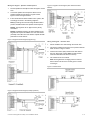
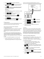
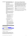
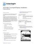
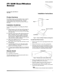
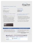
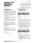
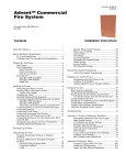
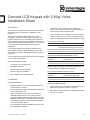
Concord LCD Keypad with 2-Way Voice
Installation Sheet
Description
The Concord LCD Keypad with 2-Way Voice provides control
of all programming and operation of compatible security
systems.
The 2-line, 16-character display provides easy to read
messages to indicate the current status of the system. The
keypad includes police, fire, and auxiliary panic buttons that
can be activated anytime. An internal piezo provides system
status beeps for trouble and alarm indications.* Two-way audio
is achieved using an internal speaker and microphone
combination.*
A supervised hardwire zone provides an additional zone
without added wiring to the panel. Opening the removable
swing-down door reveals a label with basic system operating
commands.
* Not UL approved as a primary annunciator. Not investigated
for use as two-way verification.
•
The hardwire zone is intended for use with intrusion
sensors only. This zone input does not provide power for
sensors such as PIRs, fire detectors, etc.
•
Up to 16 keypads can be installed on a Concord 4 system
of which a maximum of two can be connected to two-way
audio or a single keypad plus an audio verification module.
Table 1: Keypad Power Usage
Current (mA)
Conditions
110
Maximum alarm current with the buzzer sounding
and the keypad illuminated from a button press
60
Typical operation
23
Power saving mode (no panel AC power)
Table 2: Maximum SuperBus and Audio Wire Lengths
Wire gauge (unshielded or
shielded)
Max. keypad wire length between
keypad and panel
Tools and Equipment needed
18
750 feet
•
4-conductor, 18- or 22-gauge wire
22
300 feet
•
#2 Phillips screwdriver
•
#6 screws and anchors (included)
Note: Interlogix recommends using shielded cable to prevent
crosstalk between the speaker and microphone.
•
Screws for gang box installation
Table 3: Maximum Hardwire Zone Wire Lengths
•
Saw or utility knife for cutting wallboard
Wire gauge (unshielded or
shielded)
Max. keypad zone wire length
between keypad and sensor
22
100 feet
Installation
Installation Guidelines
Hardwire zone End of Line (EOL) resistor should be 2K ohm.
Installing the Mounting Plate
•
Mount the keypad in an environmentally controlled area
(32°F to 120°F/0°C to 49°C).
1.
Place the keypad on a flat surface so that the mounting
plate is facing as shown in Figure 1 on page 2.
•
When mounting the keypad, allow at least 6 inches below
it for the swing-down cover.
2.
Remove the mounting plate from the keypad as described
in Figure 1 on page 2.
•
When connecting two-way voice to the keypad, any
additional speaker devices on the system should be
connected in parallel with the keypad speaker connection.
Note: Siren volume will be reduced if connected in series.
This information differs from the information listed in the
Concord 4 Installation Manual.
•
Do not exceed the maximum available power given in the
panel installation instructions.
P/N 466-4434 • REV H • 13FEB15
1/9
Figure 1: Removing Mounting Plate From Keypad
To enable the tamper function:
1.
Remove the two small flathead screws that attach the
terminal block plate to the mounting plate.
2.
Mount according to the process above.
Note: Tamper screws must be installed into a stud.
Wiring the Keypad
CAUTION: Use static electricity precautions when
handling electronic components.
Utiliser les précautions de l'électricite statique lors de la
manipulation des composants électroniques.
3.
1.
Remove the panel AC and backup battery power.
2.
Run wires (18- or 22-gauge) from the panel and sensor to
the keypad location.
Place the mounting plate on the wall and mark the primary
and tamper mounting holes, making sure to leave a 6 inch
clearance below the keypad for the door to open. See
Figure 2 below.
•
4-conductor (no 2-way voice) between panel and
keypad
•
8-conductor (with 2-way voice) between panel and
keypad
Note: Interlogix recommends using shielded cable to
prevent crosstalk between the speaker and
microphone.
Note: Gang box mounting screws are not provided with
this keypad.
4.
Insert anchors into the wall at the marked locations where
studs are not present.
5.
Align the mounting plate over the selected mounting
locations and secure the back plate using the screws
provided.
•
3.
Note: Do not over tighten screws or the mounting plate
may bind and prevent the keypad from mounting properly.
2-conductor (to sensor) between keypad and hardwire
sensor (if installed)
When routing the wires, route all wiring connections from
the access area directly to the terminal, keeping wires
short and flat. No loops of wire should run outside the
access area.
Note: Do not run any excess wire outside the access area
as it will make the assembly of the keypad onto the
mounting plate difficult.
Figure 2: Marking the Mounting Holes
Wiring the Keypad – SB2000
1.
Pull the ground, +12 volt and bus wires through the access
area.
2.
Connect the Bus to the 9 position terminal block as shown
in Figure 3 below.
Figure 3: Connecting the Keypad
6.
Cut a hole in the wall at the wire access area of the
mounting plate to pull the wiring cable through.
Optional Tamper Mounting
Note: Tamper mounting hardware is not supplied with this
product.
2/9
Note: For bus wire length over 150 feet, a 120 ohm
termination resistor is needed across A to B at the panel.
Concord LCD Keypad with 2-Way Voice Installation Sheet
Wiring the Keypad – Speaker and Microphone
1.
Pull the speaker and microphone wires through the access
area.
2.
Connect the speaker and microphone wires to the 9
position terminal block as shown in Figure 4 below,
Figure 5 below and Figure 6 below.
3.
If other audio devices will be installed on the system, wire
accordingly as shown in the following diagrams.
Figure 6: Keypad to Audio Diagram (with Audio Verification
Module)
Note (1): Interlogix recommends using shielded cable to
prevent crosstalk between the speaker and microphone.
Note(2): The keypad is not UL approved as a primary
annunciator.
Note(3): Installations requiring an AVM in addition to the
Keypad Audio require the addition of a 10 K ohm resistor
(included) on the MIC wire of the AVM to equalize the MIC
performance of both devices.
Figure 4: Keypad to Audio Diagram (keypad only)
Wiring the Keypad – Hardwire Zone
1.
Pull the hardwire zone wires through the access area.
2.
Connect the hardwire zone wires to the 9 position terminal
block as shown in Figure 7 below.
3.
Insert the end-of-line (EOL) resistor at the last device in
the loop. See Figure 7 below. Note: The EOL resistor
must be located at the last device in the loop.
4.
Use a maximum of five contacts.
Note: The keypad does not supply power for sensors.
Sensor Zones must be of the normally open or closed
contact type.
Figure 7: Hardwire Zone
Figure 5: Keypad to Audio Diagram (multiple speakers)
Concord LCD Keypad with 2-Way Voice Installation Sheet
3/9
External Contact Wiring
Figure 9: Function Key Decals
Table 4: External switches
Normally closed
Normally open
Short = Tamper
Open = Tamper
2K ohm = Normal
Short = Alarm
Open = Alarm
2K ohm = Normal
Note: A bus failure will result in a zone trouble condition.
Attaching the Keypad to the Mounting Plate
1.
Align the right side of the keypad over the hooks on the
mounting plate. See Figure 8 below.
2.
Swing the left side of the keypad over the latches on the
mounting plate, until the latches snap into place. See
Figure 8 below.
Figure 8: Attaching the Keypad to the Mounting Plate
Please refer to Table 5 below or to the specific panel
installation/user manual for more information on when specific
key presses are required.
Note: The Auxiliary Alarm Key is not evaluated for and not to
be used for UL 1637 (medical) applications.
Table 5: Key Functions
Key
Function
Scroll through available options at current menu
tier
Enter pauses when programming telephone
numbers (no end user function)
Delete certain program settings
Note: To remove, depress both latches on the left side
and then swing the left side of keypad away from the wall,
removing the keypad from the hooks.
Applying Decals
A set of decals is included with the keypad for labeling the
function keys. For Concord 4, the function keys are
programmed: Fire (F1), Auxiliary (F2) and Police (F3).
Carefully apply the function key decals (as needed) on the
keypad as shown in Figure 9 below.
Also used as Quick Exit key for end-user
Power up and Bus Communication
Follow the steps below for powering up the panel and for
verifying that the keypad and the panel are properly
communicating with each other.
Note: Upon power up, the panel scans the bus for connected
devices, assigns a unit number to each bus device, and
automatically learns the device ID number of each bus device.
1.
Verify that all wiring between the panel and keypad is
correct.
2.
Connect the panel battery and restore AC power.
Alphanumeric keypads briefly show SCANNING BUS
DEVICES, then displays date and time.
Optional (steps 1 through 7)
1.
4/9
At the keypad, enter program mode by pressing 8 +
installer/dealer code (default = 4321) + 0 + 0. The keypad
should display SYSTEM PROGRAMMING.
Concord LCD Keypad with 2-Way Voice Installation Sheet
2.
Press
. The display should show SECURITY.
3.
Press
or
until the display shows ACCESSORY
MODULES, then press
. The display should show
BUS DEVICES.
4.
Press
. The display shows the lowest device address
and its ID. The following example shows what a device
address display may look like:
UNIT - ID
0—02110185*
*The 8-digit SuperBus ID number is also located on a label
on the back of the keypad.
5.
Press
or
to cycle through all bus device
addresses until the keypad appears.
6.
After verifying the keypad device ID, press
repeatedly until the display shows SYSTEM
PROGRAMMING.
7.
Press
or
until the display shows EXIT
PROGRAMMING READY, then press
. The keypad
should show the date and time display.
Figure 10: Connecting a Programming Keypad—Concord 4
2.
Activate the keypad by pressing
CODE +
+
.
3.
To program options for the newly installed keypad (such as key
beeps) see the specific panel Installation Instructions.
Enter program mode by pressing
+ installer/dealer
CODE +
+
and program the panel using the
panel Installation Instructions.
4.
When programming is completed, disconnect the
programming keypad.
Connecting the Keypad for System
Programming Only
Testing
Programming
For installations that don’t include an alphanumeric keypad as
a permanent part of the system, connect one for system
programming to the Programming Keypad Header on the
panel.
To do this, first connect a Programming Keypad Cable (60791) to the keypad wires. See the Programming Keypad Cable
Installation Instructions (P/N 466-1604), included with the
cable). Then, use the appropriate procedure for connecting the
keypad.
To connect a programming keypad to a Concord 4 panel:
1.
With the panel powered up, connect the cable to the
Programming Keypad Header Pins. See Figure 10 below.
+ installer/dealer
Note: Contact the central monitoring station before activating
alarms to avoid dispatching local police and fire departments.
Test the keypad by arming/disarming the system, activating the
keypad panics, bypassing sensors, and by turning chime and
lights on/off to verify correct operation. Refer to the panel
User’s Manual for complete system operating instructions.
Adjusting Display Brightness
The keypad display can be adjusted for easier viewing to help
compensate for lighting conditions in the keypad location.
The brightness adjustment lightens or darkens the background.
To adjust display brightness:
Concord LCD Keypad with 2-Way Voice Installation Sheet
1.
Enter user programming mode by pressing 9 + user,
partition, or system master CODE. The display shows
SYSTEM MENU, then TIME AND DATE.
2.
Press
until the display shows OPTIONS, then press
. The display should show DOWNLOADING ON/OFF
(current setting).
3.
Press
twice. The display should show KEYPAD
BRIGHTNESS 2 (default setting).
4.
Enter a setting from 0 (darkest background) to 3 (brightest
background), then press
.
5.
The display flashes the entered selection, then stops after
pressing
and displays the new setting and brightness
level.
5/9
6.
Exit user programming mode.
Status LEDs
The keypad has LEDs that indicate the current system status
at a glance. Table 6 below explains LED behavior.
Troubleshooting
Problem
Action/Solution
Keypad doesn’t power
up (no display and no
beeps when keys are
pressed).
Check for correct wiring connections at
keypad and panel terminals.
Table 6: Status LEDs
LED
System status
Solid blue (while
backlights are on)
System is disarmed, status is normal
Solid red (while
backlights are on)
System armed
Flashing red
System is in alarm
Flashing blue
System is disarmed, trouble or alarm condition
present (for example protest, low battery,
supervisory, bus trouble, tamper, open zone, etc.)
Note: Solid status LEDs display only when a key is pressed or
backlighting is on. Flashing LEDs remain flashing until the fault
or alarm condition is cleared.
Make sure panel battery is connected
correctly and that the panel transformer is
plugged in.
Make sure panel transformer is not plugged
into an electrical outlet controlled by a switch.
Relocate transformer to an unswitched outlet
location, if necessary.
Keypad status blue
LED is flashing and a
trouble star is
displayed on the LCD
indicating a trouble
condition and system
doesn’t respond to
commands from
keypad.
Check for correct bus wiring connections
(green and white wires) at keypad and panel
terminals.
No sound coming from
speakers
Check for correct wiring connections at
keypad and panel terminals.
Door and Hinge Removal
Specifications
1.
Remove the keypad from the mounting plate.
2.
Using a screwdriver, back out the hinge retainer screws
1/8”. See Figure 11.
Compatibility
Concord 4
Power requirements
12 VDC nominal
3.
Remove the door and hinges.
Current - 110 mA
Maximum alarm current
Current - 60 mA
Typical operation
Current - 23 mA
Power saving mode (no panel AC power)
Operating temperature
32° to 120°F (0° to 49°C)
Storage temperature
-4° to 140°F (-20° to 60°C)
Humidity
95% relative, non-condensing
Dimensions
5.32” x 6.03 x .092” (L x W x D)
Note: Per SIA CP-01 2010 requirements, the door must
remain attached and closed during normal operation.
Figure 11: Door and Hinge Removal
Regulatory Information
Manufacturer
UTC Fire & Security Americas Corporation, Inc.
1275 Red Fox Rd., Arden Hills, MN 55112-6943,
USA
UL listings
UL 985 Household Fire Warning System Units
UL 1023 Household Burglar-Alarm System Units
UL1610 Central Station Burglar-Alarm Units
(Commercial Burglary)
Note: See specific panel Installation Instructions
for complete UL installation requirements.
Not investigated by UL for use as a medical alert.
6/9
Concord LCD Keypad with 2-Way Voice Installation Sheet
FCC compliance
FCC Part 15 Information to the User
Changes or modifications not expressly approved
by Interlogix can void the user’s authority to
operate the equipment.
FCC Part 15 Class B
This equipment has been tested and found to
comply with the limits for a Class B digital device,
pursuant to part 15 of the FCC Rules. These
limits are designed to provide reasonable
protection against interference in a residential
installation.
This equipment generates, uses, and can radiate
radio frequency energy and, if not installed and
used in accordance with the instructions, may
cause harmful interference to radio
communications. However, there is no guarantee
that interference will not occur in a particular
installation.
damages under any theory of liability, whether based in
contract, tort, negligence, product liability, or otherwise.
Because some jurisdictions do not allow the exclusion or
limitation of liability for consequential or incidental damages the
preceding limitation may not apply to you. In any event the total
liability of Interlogix shall not exceed the purchase price of the
product. The foregoing limitation will apply to the maximum
extent permitted by applicable law, regardless of whether
Interlogix has been advised of the possibility of such damages
and regardless of whether any remedy fails of its essential
purpose.
Installation in accordance with this manual, applicable codes,
and the instructions of the authority having jurisdiction is
mandatory.
While every precaution has been taken during the preparation
of this manual to ensure the accuracy of its contents, Interlogix
assumes no responsibility for errors or omissions.
If this equipment does cause harmful interference
to radio or television reception, which can be
determined by turning the equipment off and on,
the user is encouraged to try to correct the
interference by one or more of the following
measures:
•
Reorient or relocate the receiving antenna.
•
Increase the separation between the
equipment and receiver.
•
Connect the affected equipment and the
panel receiver to separate outlets, on
different branch circuits.
•
Consult the dealer or an experienced
radio/TV technician for help.
This Class B digital apparatus complies
with Canadian ICES-003.
•
Cet appareil numérique de la classe
B est conforme à la norme NMB-003 du
Canada.
•
L’utilisation de ce dispositif est autorisée
seulement aux conditions suivantes :
(1) il ne doit pasproduire de brouillage et
(2) l’utilisateur du dispositif doit être prêt à
accepter tout brouillage radioélectrique reçu,
même si ce brouillage est susceptible de
compromettre le fonctionnement du
dispositif.
Contact Information
For general information, see www.interlogix.com. For
customer/technical support, see www.interlogix.com/customersupport or call +1 855 286 8889.
© 2015 United Technologies Corporation. Interlogix is part of
UTC Building and Industrial Systems, a unit of United
Technologies Corporation. All rights reserved.
Limitation of Liability
To the maximum extent permitted by applicable law, in no
event will Interlogix be liable for any lost profits or business
opportunities, loss of use, business interruption, loss of data, or
any other indirect, special, incidental, or consequential
Concord LCD Keypad with 2-Way Voice Installation Sheet
7/9
Installer: Please provide this page to the end user.
8/9
Concord LCD Keypad with 2-Way Voice Installation Sheet
Concord LCD Keypad with 2-Way Voice Installation Sheet
9/9