1
The set up of a measuring platform for
Electromagnetical Compatibility measurements.
G. van Vugt
WFW Report 96.106
G. van Vugt
id. nr. 362163
Training report
Companions: Mr. J. Weexsteen
Ir. J.P.A. Banens
Eindhoven, july 1996
Eindhoven University of Technology, department of Mechanical Engineering
Institut Catholic d’A r t s et Métiers Nantes, department of Control Engineering
TU Eindhoven / ICAM-Nantes, July 1996
The set up of a measuring platform for EMC
Summary
Since the lst of January 1996, European rules make that all products, which are sold on the European market,
have to be equipped with a European mark, CE. To have the right to carry that mark, the product must satisfj
certain demands, which are established by European standards, under which the standards of Electromagnetical
compatibility (EMC).
fer E!ectrotecbnicz! Stadwdisation develops the General Stadards. These we
The E ~ c p e a r Qrgmisztior,
,
standards with a wide application, not related to any particular product family. They can be split in two parts:
emission and immunity. The limits of emission make that the product doesn’t disturb other machines in its
neighbourhood. The limits of immunity make that the machine will keep working even in an electromagnetic
polluted environment.
Each apparatus which is placed on the market or taken into service and which is liable to cause electromagnetic
disturbance or which is itself liable to be affected by such disturbance have to be tested to look if the product
meets the required limits.
These tests are done at a measuring platform. The purpose of this project is to set up such a platform. The
European Standards are examined to look which test equipment is needed, which distances have to be respected
etc. All this relevant information is combined in guide lines for the people who carry out the different tests.
In these guide lines is step by step in a readable manner explained what the person has to do to carry out the tests
according to the standards. The tests which have to be carried out to cover the requirements of the standards, will
include conducted and radiated RF emissions plus immunity to transients and electrostatic discharge.
At the end of the tests a test report must be made. In this test report should exactly be written how, where, with
which equipment the tests are done.
Finally the platform is set up. The need of a Cage of Faraday was inevitable to keep the high environmental noise
outside. To be sure that the equipment doesn’t exceed the limits, a safety margin of 5 dB is used. The places of
the equipment is indicated with signs on the floor. At the end the platform is ready to be used for
electromagnetical (pre)compliance testing.
-2-
Tu Eindhoven / 1CAM.Nantec. July 1996
The set up of a measuring platform for EMC
Contents
SUMMARY ............................................................................................................................................................ 2
.
..............................................................................................................................................
1 INTRODUCTION
.
............................................................................................................................................
2 THE STANDARDS
4
5
2.1. INTRODUCTION
.................................................................................................................................................. 5
2.2. THEEMC-STANDARDS
......................................................................................................................................
6
2.3. WMCH PRODUCTS MUST BE TESTED ? ................................................................................................................
8
2.4. TESTING
AND TEST-HOUSES ...............................................................................................................................
8
2.5. THE CE MARK AND THE DECLARATION OF CONFORMITY ...................................................................................
9
.
3 THE GUIDE LINES
........................................................................................................................................
3.1. INTRODUCTION
................................................................................................................................................
10
10
3.2. RADIATED EMISSION TESTING .............................................................................
3.3. CONDUCTED EMISSION TESTING.......................................................................................................................
12
............................................................................
12
.............................
13
3.4. ESD IMMUNITY TESTING ..... ......................................
3.5. TRANSIENT
BURST ~
.
4 TEST REPORT
T .........................................................................
Y
................................................................................................................................................
4.1. INTRODUCTION ................................................................................................................................................
15
15
4.2. CONTENTS
....................................................................................................................................................... 15
........................................................................................
17
5.1. INTRODUCTION
................................................................................................................................................
17
5.2. SETTING
up......................................................................................................................................................
17
5 .PLACING OF THE MEASURING PLATFORM
................................................................................................................................................
19
ANNEX A: THE GUIDE LINES ........................................................................................................................
20
6. CONCLUSION
............................................................................
ANNEX B: THE DETAILS OF THE TEST-EQUIPMENT
69
LITERATURE ..................................................................................................................................................... 70
-3-
~~
Tu Eindhoven / ICAM-Nantes, July 1996
The set up of a measuring platform for EMC
1.
Introduction
Since the lst of January 1996, European rules make that all machines which are sold on the European market,
have to be equipped with a European mark, CE. If the product doesn’t have that mark, it can be removed fiom
the market and engender severe punishments. On the other hand, a product with the mark can be sold on the
entire European market, without any national supplemental demands. To have the right to carry the mark CE, the
product must satisfy certain demands, which are established by European standards, under which the standards of
eiectromagnetic compatïoility (EMC).
These standards can be split in two parts: emission and immunity.The limits of emission, radiating as well as
conducting, make that the product doesn’t disturb other machines in its neighbowhood. The limits of immunity
make that the machine will keep working even in an electromagnetic polluted environment.
The purpose of this project is to set up a platform where measurements can be taken to look if the tested product
meets the required limits concerning EMC. In the future, the intention is to do measurements for enterprises for
the Cpre)compliance tests of their products. Precompliance tests enables the manufacturer to do tests in an early
stage of the development of a new product. In this way a lot of money can be saved, because if faults can be
removed in an early stage of development, it prevents a lot of trouble and is much cheaper than if that is done in
the fmal stage of development.
This project is the result of an Erasmus international exchange of students between the Eindhoven University of
Technology (TUE) and the school for mechanical engineers, Instikt Catholic d’Arts et Métiers (ICAM) in
Nantes. For three months a Dutch student worked in a French laboratory of control engineering to set up the
measuring platform mentioned above. As the intention is that that platform is used by French people, some parts
of this report (like user-manuals) are written in French.
-4-
The set up of a measuring platform for EMC
2.
TU Eindhoven / ICAM-Nates. Julv 1996
The standards
2.1. Introduction
Of the various aims of the creation of the Single European Market, the free movement of goods between
European states is fundamental. All member states impose standards and obligations on the manufacture of goods
in the interests of quality, safety, consumer protection and so forth. Because of detailed differences in procedures
and requirements, these act as technical barriers to trade, fragmenting the European market and increasing costs
because manufacturers have to modify their products for different national markets.
For many years the EC tried to remove these barriers by proposing Directives which gave the detailed
requirements that products had to satisfy before they could be freely marketed throughout the Community, but
this proved difficult because of the detailed nature of each Directive and the need for unanimity of the members
before it could be adopted. To accelerate the project, the Directives are limited to setting out only the essential
requirements which must be satisfied before products may be marketed anywhere within the EC. The technical
detail is provided by the European staiïdards drawn üp by the European standards bodies CEN (European
Organisation for Standardisation), CENELEC (European Organisation for Electrotechnical Standardisation) and
ETS1 (European Telecommunications Standards Institute). Also are the decisions on new approach Directives
taken by qualified majority voting, eliminating the need for unanimity and so speeding up the process of
adoption.
At this moment, there are about 17700 French Standards, 3300 European Standards and 13000 International
Standards. National Standards can be facultatively taken from the International Standards, with or without
modifications. On the other hand, each member is required to implement the European Standards, without
modifications, into National Standards, with withdrawal of the divergent National Standards. This means, that
products which are found to comply within one state are automatically deemed to comply within all others, no
member state can refuse them entry on technical grounds. This implies subsequently, that the product, to can be
sold on the entire European Market, has to pass just one test.
The mark CE, will be present on all the products which are sold on the European Market, so it can’t be used by
the customer to guide his choice. To distinguish the products and enterprises other, voluntary marks are available.
Such as NF in France, GS in Germany and Kite-Mark in Great-Britain for products and IS0 9000 for enterprises.
In this chapter the structure of the EMC standards will be described. Further is explained when an apparatus must
be tested and when the CE mark can be affixed to the product.
-5-
TU Eindhoven / ICAM-Nantes, July 1996
The set up of a measuring platform for EMC
2.2. The EMC-standards
One group of standards are the EMC-standards. The ever greater use of electronic equipment around the world
has led to an increasing awareness of the importance of electromagnetic compatibility. This is defined as the
ability of a device, unit of equipment or system to function satisfactorily in its electromagnetic environment
without introducing intolerable electromagnetic disturbances to anything in that environment. So the term EMC
has two complementary aspects:
it describes the abiliv of electrical and electronic systems to operate without interfering with other
systems + the emission
it also describes the ability of such systems to operate as intended within a specified electromagnetic
environment + the immunity
Because of the importance of EMC, great effort has been expended over recent years in designing methods of
measurement of EMC performance, in laying down acceptable (and achievable) standards of performance and in
drafting legal requirements to impose compliance with these standards on manufacturers of electronic equipment.
The structure of the EMC-standards is as follows:
1. Basic Standards
2 . General Standards
3. Standards of product families
4. Standards dedicated to specific products
There are many industry sectors for which no product-specific standards have been developed. In order to fill this
gap wherever possible, CENELEC have given a high priority to developing the General Standards. These are
standards with a wide application, not related to any particular product or product family, and are intended to
represent the essential requirements of the Directive. They are divided into two standards, one for immunity and
one for emissions, each of which has separate parts for different environment classes. Where a relevant productspecific standard does exist, this takes precedence over the generic standard.
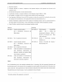
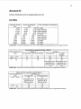
The interesting standards for this project are given in Table 1.
In these standards is also indicated which test equipment is required to carry out the test. To do the tests in
accordance with the standards, the following test equipment, mentioned in these standards, is bought*:
Burst Tester, to couple nanosecond spikes into the mains EUT (Equipment Under Test) supply or into data
and communication lines with the
HF-Coupling Clamp
Electro Discharge Tester, produces electrostatic discharges to evaluate the performance of the electrical
equipment under test
-6-
Tu Eindhoven / ICAM-Nantes, July 1996
The set up of a measuring platform for EMC
p Spectrum Analyser,
p Computer Interface, to connect a computer to the spectrum analyser so the spectrum can be seen on the
computer screen
p E and H near-field probes, to locate emission sources
p Log-Periodic Antenna, to measure radiation over the frequency range 30 Mhz to 1 GHz.
p Pre-amplifier,to ampli@ the low level signals of the antennas and near field probes,
p Line Impedance StabilisationNetwork (LISN), machine to imitate the required fictive network and to provide
the transducer for measurement of RF conducted back down the mains from the EUT.
p Isoiation Transformer, required for the LISN, because of its ieakage currents it can't be connected directiy to
the mains supplies of the laboratory, for the earth leakage circuit breaker will be immediately activated
p Cage of Faraday, needed to keep the environmental parasites outside
Emission
Immunity
EN 5008 1- 1 Generic emission standard
EN 6 1000-4-1
Electromagnetic
Part
Compatibility
4:
Testing and
Part 1: Residential, commercial and
(EMC)
light industry
measurement techniques - Section 1:
-
Overview of immunity tests - Basic
EMC publication
EN 50081-2
EN 61000-4-2
Part 2: Industrial environment
Section 2: Electrostatic discharge
immunity test
EN 50082-1
EN 61000-4-4
Generic immunity standard
Part 1: Residential, commercial and
Section 4: Electrical fast transient /
burst immunity test
light industry
EN 50082-2
Part 2: Industrial environment
EN 5501 1
Limits and methods of measurement of
radio disturbance characteristics of
industrial, scientific and medical (ISM)
radio-fiequency equipment
EN 55022
Limits and methods of measurement of
radio disturbance characteristics of
information technology equipment
Table 1
Not all information given in the standards mentioned above is interesting. Only the interesting information and
the information given in the manuals of the test-equipment are joint together in the guide lines for the person who
carries out the test. These guide lines are written in French as the person who carries out the tests will be French.
The guide lines can be found in annex A and are explained in the next chapter.
* For further details of the equipment, see annex B
-7-
~~
The set up of a measuring platform for EMC
Tu Eindhoven / ICAM-Nantes, July 1996
2.3. Which products must be tested ?
The EMC Directive applies to an apparatus which is placed on the market or taken into service and which is
liable to cause electromagnetic disturbance or which is itself liable to be affected by such disturbance.
«Apparatus» is defined as all electrical and electronic appliances, equipment and installations.
((Placingon the market» means the first making available of the product within the EC, so that the Directive
covers only new producîs man-üfactured -with îhe EC, but bo’& ne-w and Used pïodiücts Lqoïted
fï~-
a tEìd
country. If the product is manufactured in or imported into the EC for subsequent export to a third country, it has
not been placed on the market.
((Taken into service))means the first use of a product in the EC by its final user. If the product is used without
being placed on the market, if for example the manufacturer is also the end user, then the protection requirements
of the Directive still apply. On the other hand, it should not need to go through the conformity assessment
procedures to demonstrate compliance. So the test-site which will be set up, can also be used to look if the
equipment ICAM makes for itself doesn’t exceed the given limits.
~
If the manufacturer resides outside the EC, then the responsibility for certi@ing compliance with the Directive
rests with the person placing the product on the market for the fEst time within the EC, i.e. the manufacturer’s
from already existing
authorisedrepresentative or the importer. Any person who produces a new f ~ s h e product
d
finshed products, such as a system builder, is considered to be the manufacturer of the new finished product.
The question of when does a component (which is not within the scope of the Directive) become apparatus
(which is) remains problematical. The Commission’s interpretative document defines a component to be «any
item which is used in the composition of an apparatus and which is not itself an apparatus with an intrinsic
function intended for the final consumer)). Thus individual parts such as ICs and resistors are definitely outside
the Directive.
2.4. Testing and test-houses
Except in the case of products which clearly will intrinsicallynot cause interference or be susceptible to it, such
as a pocket torch, each manufacturer will need to submit products to some degree of EMC testing to be sure that
they comply with the Directive. To cover the eventual requirements of the standards, the scope of the tests will
need to include conducted and radiated RF emissions plus immunity to transients and electrostatic discharge. A
test facility to address all these phenomena at compliance level is beyond the budget of most small to medium
sized companies. A large company may have the product volume and available capital which justifies investment
in an in-house facility. Small to medium sized enterprises which are not able to afford their own full-scale test
facilities, will often make use of independent test houses, as ICAM will become one.
-8-
~
TU Eindhoven / ICAM-Nantes, July 1996
The set up of a measuring platform for EMC
2.5. The CE mark and the declaration of conformity
The manufacturer or his authorised representative is required to attest that the protection requirements of the
Directive have been met. This requires two things:
he issues a declaration of conformity which must be kept available to the enforcement authority for
ten years following the placing of the apparatus on the market
he affixes the CE mark to the apparatus, or to its packaging, instructions or guarantee certificate
The EC declaration of conformity must include the following components:
a description of the apparatus to which it refers
a reference to the specifications under which conformity is declared, and where appropriate to the
national measures implemented to ensure conformity
an identification of the signatory empowered to bind the manufacturer or his authorised
representative
The mark consists of the letters CE as shown in figure 1. The mark should be at least 5 mm in height and be
affixed visibly, legibly and indelibly.
~~
~
Figure 1: The CE-mark
-9-
The set up of a measuring platform for EMC
Tu Eindhoven / ICAM-Nantes, July 1996
3. The Guide lines
3.1. Introduction
For the standards contain much more information that is interesting for this project, guide lines are formulated
(see annex A). These guide lines contain only the relevant information of the standards. This prevents the person
who carries out the test to read the standards, which are not always as easy to read.
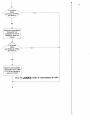
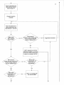
It is tried to translate the information of the norms in a readable manner. Therefore is step by step in a flow chart
explained what the person has to do to cany out these tests according to the standards.
In this chapter these guide lines are further explained where necessary.
3.2. Radiated e m i s s l testing
~~
~
~
For ease of measurement and analysis, radiated emissions are assumed to predominate above 30 M h z and
conducted emissions are assumed to predominate below 30 Mhz. There is of course no magic changeover at 30
Mhz, but typical cable lengths tend to resonate above 30 Mhz, leading to anomalous conducted measurements,
while measurements of radiated fields below 30 Mhz will necessary be made in the near field, which gives results
that do not necessarily correlate with real situations.
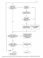
The first guide line has to check the radiated emission of the EUT. The first page is to look which standard is
applicable and to which class and group the apparatus belongs, this is important to chose the right limits. On the
next page, is told how to place the EUT and the necessary test equipment, as described in the standards. The EUT
has to be positioned so that its boundary is at a specific distance from the measuring antenna, normally this
distance is 3 meters. A non-floor-standing EUT should be 0.8 m above the ground plane. The EUT needs also to
be rotated 360" to find the maximum emission.
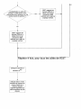
After that, the settings of the analyser and computer are given. There are two kinds of detector in common use in
emissions measurements: quasi peak and average. The quasi-peak detector is a peak detector with weighted
charge and discharge times which correct for the subjective human response to pulse-type interference.
Interference at low pulse repetition frequencies (PRF) is subjectively less annoying on radio reception than that at
high PRFs. Therefore, the quasi-peak response de-emphasises the peak response at low PRFs. The average
detector, as its name implies, measures the average value of the signal. For a continuous signal this will be the
same as its peak value, but a pulsed or modulated signal will have an average level lower than the peak. The
- 10-
TU Eindhoven / ICAM-Nantes, July I996
The set up of a measuring platform for EMC
effect of this is to penalise
continuous
emissions
with
respect to pulsed interference,
which registers a lower level on
an average detector.
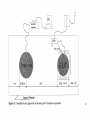
Figure 2: Reflected and direct waves captured by the antenna
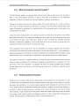
Then the height of the antenna
has to be adjusted, such that the
received signal is as strong as possible. That is needed, because the antenna not only measures the direct signal
kom the EUT, but also any signals that are reflected from conducting objects such as the walls, the ground plane
and the ceiling. They are not equipped with anti-reflection cones, to prevent the investment being too large. On
the other hand, 3 movable panels are equipped with absorbing cones. These panels are placed just next to the
EUT (see figure S), to prevent reflections as much as possible. The remained reflections cause points where the
waves extinguish each other as well as points where the waves are amplied. By varying the height of the antenna,
the relative distances of the direct and reflected paths change, see figure 2. To do reproducible measurements the
antenna has to be placed in one of the points where the waves are amplified as much as possible.
Now the environmental noise is measured. As the tests are done in a cage of Faraday, there will be no problems
with the strength of the environmental noise. So this is just done to veri3 if the cage shows no leakage. Then the
emission of the EUT is measured and checked to stay within the given limits. It is wise to respect a safety margin
of 5 dB under the given limits, because it is practically impossible to do reproducible measurements and also
because the cage is not completely equipped with anti-reflection cones. If it doesn’t exceed the limits minus 5 dB,
the EUT respects the norms EMC as far as the radiated emission is concerned.
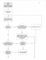
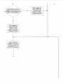
If the given limits minus 5
short exposed length
dB
are exceeded, the
sources of the concerned
frequencies are tried to be
inner soldered
found, with the near field
screen at
probes. These detect field
strength in the near field.
Therefore two types of
probe are needed, one for
Figure 3: Nearfieldprobes
the electric field (rod
construction) and the other for the magnetic field (loop construction) (see figure 3). The electrical field probe
will detect nodes of high dv/dt, while the magnetic field probe will detect paths of high di/dt. As soon as the
components, which produces the concerned hequencies are found, it is tried to give a solution to the problem. In
this way the manufacturer of the EUT can change the design of his product, so it can meet the given limits.
-
11 -
~~
~
The set up of a measuring platform for EMC
TU Eindhoven / ICAM-Nantes, July 1996
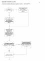
3.3. Conducted emission testing
The second guide line talks about conducted emission on the mains port. As said before, this concerns only
emitted frequenciesbelow 30 Mhz.
To make these tests, an artificial mains network or Line Impedance Stabilising Network (LISN) is needed to
provide a defined impedance at RF across the measuring point, to couple the measuring point to the test
instrimvntztion and to isolate the test circait from -mwanîed interference signals on the supply mains. -When the
LISN is exposed to the 240 V line voltage there will be a current of about 0.75 A in the safety earth. This level of
current is lethal, and the unit must therefore be solidly connected to earth for safety reasons. If it is not, the LISN
case, the measurement signal lead and the EUT can all become live. A secondary consequence of this high earth
current is that LISNs cannot be used on mains circuits that are protected by earth leakage or residual current
circuit breakers. It is therefore that an isolation transformer is used between the local power supply network and
the LISN.
The
requirement is placement
O 8m (CISPR)
Vertical
ground plai
(wall of
screened
enclosure)
+-----+
principal
excesslead
bundled
of the EUT with respect
< O 4m length (CISPR)
to the ground plane and
the
mains lead 1m
LISN,
and
the
disposition of the mains
cable
and
earth
Ground plane 2m x 2m min (CISPR)
to measuring instrument
connection(s). This
is
given in the guide lines
Figure 4: L q o u t fo. conducted emission tests
and also show in figure
4.
There are measurements taken as well on the live as on the neutral wire. Here will also be tried to give
suggestions to ameliorate the tested product if it exceeds the given limits.
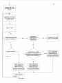
3.4. ESD immunity testing
The third guide line will test the electrostatic discharge immunity of the EUT. For the tests, the EUT should be
set up in its operating configuration.The connection to the ground is important, and this should be representative
of installation or user practice. Table-top equipment should be placed on a wooden table 80 cm over the ground
plane, with a horizontal coupling plane directly underneath it but insulated Porn it. The coupling plane must be
connected with the ground, using a cable equipped with a 470 kL2 resïstance at each end, Floor standing
equipment should be isolated from the ground plane by an insulating support of about 10 cm.
-12-
~
-~
TU Eindhoven / ICAM-Nantes, July 1996
The set up of a measuring platform for EMC
After the equipment is installed, the points to which the electrostatic discharges are executed are chosen. These
points have to be points which are accessible to the operator during normal utilisation or maintenance. Also the
level of the electrostatic discharge has to be chosen, this depends on the relative humidity of the air and the
material of which the equipment consists. Finally there has to be decided if contact discharges or discharges in
the air are applied. Contact discharge is preferred, but this requires that the EUT has conducting surfaces or
painted surfaces which are not regarded as insulating. For a product where this is not possible (e.g. with an
overall plastic enclosure) air discharges are used.
During the tests, the tension is increased until the apparatus stops working or until the chosen level is reached. If
the apparatus stops working before the chosen level is reached and the malfunction is not temporary or
recoverable, the EUT doesn’t respect the standards. If the malfunction is temporary or recoverable, the EUT does
respect the standards as far as direct electrostatic discharges are concerned. Then the apparatus can be classified
as a class 2 or class 3 apparatus, which depends on the system needing an intervention of an operator (class 3) or
not (class 2) to restart it. And if the chosen level is reached and the apparatus still works properly, the EUT
respects the standards and will be a class 1 apparatus.
After that also indirect electrostatic discharges are applied. These are executed using vertical coupling planes,
~
~~
placed at a distance of 1O cm to the EUT, which simulate equipment which is situated next to the EUT. The same
criteria as above are used to decide whether or not an apparatus respects the norms. At the end the level of test
and the class to which the apparatus belongs are written in the user manual of the apparatus.
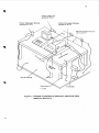
3.5. Transient burst immunity
The fourth and last guide line will test the immunity of the EUT to bursts on the main supply. Also here table top
EUTs are placed on an insulating table 80 cm above the ground, and floor standing equipment is stood off fi-om
the ground plane by a 1O cm insulating block. I/O cables are fed through the capacitive clamp which is located 1O
cm above the ground plane and connected to the burst generator.
Typically, bursts are applied for a duration of 1 minute in each polarity. The required voltage levels are defined
in the relevant standard, and vary depending on the anticipated operating environment. The burst consists of
many spikes (see figure 5). The burst frequency is 3 Hz and the length of the burst is about 15 ms. The spike
frequency depends on the chosen voltage level. When surges are applied to the mains input, they are
qynchronised with the mains waveform so as to occur at the worst case point on it (normally the positive and
negative peaks).
Here also the apparatus is categorised in the same classes as with the electrostatic discharge:
0
Class 1: the apparatus keeps working properly
- 13 -
Tu Eindhoven / ICAM-Nantes, July 1996
The set up of a measuring platform for EMC
o
Class 2: temporary malfunction or self-recovering
0
Class 3 : malfunction which need the intervention of an operator.
At the end the level of test and the class to which the apparatus belongs are written in the user manual of the
apparatus.
/ Spike
U
t
\
U
i
/
The period of repetition (depends of the voltage level)
Burst
.
t
The period of the burst. 300 ms
Figure 5: Properties of bursts and spikes
- 14-
Tu Eindhoven / ICAM-Nantes, July 1996
The set up of a measuring platform for EMC
4.
Test report
4.1. Introduction
When all tests are done, the results have to be presented in a test report. In this report must exactly be described
how, where and with what the tests are executed, so that other people eventually can reproduce the
measurements. Finally conclusions are drawn from the measuring results: the apparatus does or doesn’t respect
the European standards. If it doesn’t, it is tried to give suggestionsto adapt the design of the product.
The contents of the test report are described in the next section.
4.2. Contents
Introduction
Here is told why it is so important to test the electromagnetical compatibility of an apparatus Also is told that doing
precompliance tests can save money an a lot of trouble
2
Information of the company for which the tests are done
Here is given the name, address and phone and fax number of the company for which the tests are done Also is the name (and
phone number) of the contact person given
3.
Description of the EUT
The basic description of the EUT must specify the model number
0
Is the EUT stand-alone or part of a larger system ?
If it is to be tested as a stand-alone unit then no further information is needed If it can only be tested as part of a system then the
components of the system of which it is a part must also be specified Care must be taken that the test results will not be
compromised by a failure on the part of other system components
0
System configuration and criteria for choosing it
Ifthe EUT can form part of a system or installation which may contain many other different components, you will need to specify
a representative system configuration which will allow you to perform the tests The criteria on which the choice of configuration
is based must be clear
4.
The tests to be performed
Which standard is used ?
In the standard, the applied voltage levels and frequency ranges are specified
0
Test equipment and facility to be used
e
Location of test points
The number of lines to be tested In some cases just one representative line can be tested and claimed that it covers all others of
the same type The position of the test point can be critical, especially for electrostatic discharge application, and must be
specified The choice of ESD application points should be supported by an assessment of likely use of the equipment andor some
preliminary testmg to determme weak pomts
0
EUT operating modes
Ifthere are several different operating modes, then it may be possible to identify a worst case mode
-15-
Tu Eindhoven / ICAM-Nantes, July 1996
The set up of a measuring platform for EMC
0
Test schedule, including sequence of tests
The order m which tests are applied may or may not be critical, but should be specified
Requirements of the test facility
0
Environmental conditions
Special requirements for temperature, humidity, vibration etc
0
Safety precautions needed
if the EUT uses ionising radiations or extra high voltages, is dangerously heavy or hot, or if the tests require high values of
radiated field
Sketch and details qf test set-up
Physical location and layout of EUT and test instrumentation
Critical pomts are distances, orientation and proximity to other objects, especially the ground plane The fmal test report should
include photographs which record the set-up
0
Electrical interconnections
Cable layout and routing has a critical effect at high frequencies and must be closely defied Also the types of connector and
cable to the EUT should be specified, if they would otherwise go by default
Test results
Conclusions
interpretation of the test results Does the apparatus meet the given standards, or doesn’t it 7 If it doesn’t, suggestions to change
the apparatus must be given Also must be noted if a warning message must be noted m the manual
~
~
- 16-
TU Eindhoven / ICAM-Nantes, July 1996
The set up of a measuring platform for EMC
5. Placing of the measuring platform
5.1. Introduction
In the end, the purpose of this project is to set up a measuring platform where equipment can be tested,
concerning the European EMC standards. In this chapter, the choices which are made to set up such a platform
are explained.
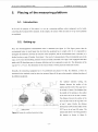
5.2. Setting up
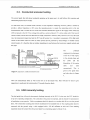
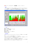
First, the electromagnetical environmental noise is measured (see figure 6). This figure proves that the
environmental noise is much larger than the limits the equipment has to comply with. So it is impossible to
distinguish the difference between the emission of the equipment, and the environmental noise. Therefore, it is
decided to place a cage of Faraday. From figure 7, the result of a measurement of the environmental noise in the
~~
cage, can be seen that disturbing external sources are hardly noticeable. The cage is also equipped with three
panels with HF-absorbing cones to decrease reflections and so to approach an open site. The dimensions of the
cage are 7.5 x 3.4 x 2.5. The dimensions of the room in which it will be placed are taken into account.
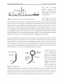
Secondly, the measuring equipment has to be positioned and placed. For this, the distances, as they are
mentioned in the standards, must be taken into account. Signs will be put on the ground to indicate the place of
the different equipment.
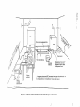
For radiated emission testing, the
distance between the outline of the
antenna and the wall of the cage has to
i
l
be at least 0.5 meter. The distance fiom
the middle of the antenna to the outline
of the EUT has to be at least 3 meters.
The distance between the outline of the
EUT and the walls of the cage has to be
7m
/085m
j
3m
-~
/
max 1 4 m
I min 7 m
I
1.
~
at least 1 meter. Finally, the distance
between the LISN and the outline of the
___
~____-
Cage of Faraday
EUT has to be at least 0.8 meter. The
antenna and the EUT are being placed in
Figure 8: Layout for radiated emission testing
the manner as shown in figure 8,
- 17-
~
TU Eindhoven / ICAM-Nantes, July 1996
The set up of a measuring platform for EMC
respecting all distances mentioned above. All other necessary equipment is being placed as much as possible
outside the cage, as also shown in figure 8.
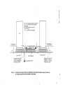
For the conducted emission testing the
distance between one wall and the EUT
must be 0.4 meter. The distance between
I 1
all other walls and the EUT must be at
LISN
t
least 0.8 meter. Here also the distance
between the LISN and the EUT has to
be 0.8 meter. All other necessary
equipment are placed outside the cage.
So the equipment to do the conducted
emission testing is placed as shown in
/
figure 9.
Cage of Faraday
Figure 9: Layout for conducted emission testing
~
_ _
-
~~~~
For the electrostatic discharge immunity
No distances are prescribed
testing no distmces we given, which
have to be respected. It is decided to
~~
~
carry out these test at the same place in
the cage of Faraday as with the radiated
emission tests (See figure 10).
By the transient burst immunity testing,
Cage of Faraday
Figure 10: Layout for both ESD and transient burst immunity testing
the distance between the EUT and all
other conducting surfaces must be at
least 0.5 meter. This distance is respected if the EUT is placed at the same place as with the radiated emission
tests. So also the layout for the transient burst immunity testing is given in figure 10. The wires between the EUT
and the test equipment must be at most 1 meter.
-18-
Tu Eindhoven / ICAM-Nantes, July 1996
The set up of a measuring platform for EMC
6.
Conclusion
The intention was to set up a measuring platform to do EMC measurements. After three months the measuring
platform was almost ready. Some test measurements are done for the emission testing and the electrostatic
discharge immunity testing. Only the transient burst testing has not yet been set up. It is decided to do that
somewhat later, when the people working with the platform already have some experience with the emission and
ESD testing. With the made guide lines the rules, with which the measurements should be done, are clear and
nothing wiii be forgotten.
Because the cage is not totally equiped with absorbing cones, two interesting tests can be made to veri6 if the
margin of 5 dB under the given limits of the rayonning emission test is sufficient. The first test is to compare the
measured emission of a EUT in this cage with the measured emission of the same EUT in a cage which is totally
equiped with absorbing cones. ICAM has that possibility, because DICOMTECH has a cage of Faraday which is
said to simulate well an open field area. They already proposed to do some verification measurements. If the
difference between the two measurements is greater than 5 dB, the margin must be adapted. Another possibility is
to buy a “EUT” of which exactly is known which level of disturbance should be measured at a distance of 3
meters of the apparatus in an open field area. If the real measured level of disturbances differs more than 5 dB,
~
~~
the margin must be adapted.
Further in the kture, if the experience of the people working with the measuring equipment is great enough, it is
possible to expand the possibilities of the platform, by buying equipment to do also rayonning immunity tests. To
do these test it is really necessary that the cage of Faraday is totally equiped with absorbing cones, because the
emitted waves are much stronger than the emitted waves of a EUT, and thus causing more and stronger
reflections.
It is clear that ICAM will have a lot of benefit of this measuring platform. Not only for their own products, but
certainly also to test products of other companies. During the set up of the platform some companies were already
interested in the possibilities of such a measuring platform in the neighbourhood. As far as I’m concerned this
platform will be as well technically as economically a big succes for ICAM.
- 19-
Tu Eindhoven / ICAM-Nantes, July 1996
The set up of a measuring platform for EMC
Annex A: The guide lines
- 20 -
ICAM - N a t e s
Laboratoire Automatique
Carquefou,juiiiet 1996
Auteur:
Gwen VAN W G T
Accompagnateur: Joseph WEXSTEEN
Table des matières
.
1 DIRECTIVES
1.1.
1.2.
1.3.
1.4.
.
............................................................................................................................................
Emission Rayonnée .....................................................................................................................
Emission Conduite ....................................................................................................................
Immunité, décharges d’électricité statique .................................................................................
Immunité, transitoires électriques rapides en salves ...................................................................
.................................................................................................................................................
ANNEXES................................................................................................................................................
2 FIGURES
3
4
10
17
24
28
35
Annexe A: Notes sur la sélection des niveaux des transitoires électriques rapides en salves ..................36
Annexe B: Notes sur la sélection des niveaux des décharges d’électricité statique.................................
40
Annexe C: Contenu des fíchiers CEM et des programmes dans le générateur de salves ........................
41
Annexe D: Limites d’émission pour les equipements sous test .............................................................. 46
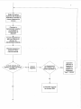
I. Directives
Disposifif à soumeffre a un tesf
Emission Rayonnée
A
(EN 55011 et EN 55022)
Non+
NF EN 55011
est
applicable
4
Est-ce que I'énergie à
fréquence radioélectriqueest
utilisée pour le traitement de la
matière2?
Oui
t
I NF
I
Oui
Elk' 55022 I
applicable
est
1
Groupe 2
L
I
I
i
L'appareil est4 prévu
pour être utilise dans les
locaux domestiques ?
Non-
1
I
/L'appareil
est4 raccordé\
I
I
I
rL
Oui
Classe B
'1
2,
Appareit de Traitement de I'lnformation
Par exempte un appareit à éiectro-érosion
.
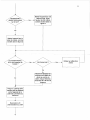
5
Mettre I'appareil sur une
table en bois, d'une
hauteur de 0,8 metres
comme dans la figure 1
Mettre I'appareil sur le
plan de masse comme
dans la figure 1
I
1
a-t-il une longueur de 1
Non
.
Non+
Utiliser un cable d'un
metre
òui
Oui
Réunir en faisceau les
longueurs de cables en
exces au centre du
cable, chaque faisceau
mesurant 30 à 40 cm de
longueur
.
t
Placer le LISNI de
façon à ce que la
distance entre I'appareil
et le LISN soit de 0,8
metres au minimum
Raccorder le fil
d'alimentation au LISN
!
Line Impedance Stabilisation Network
I
I
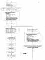
6
Poser I'antenne à une
distance de 3 metres de
I'amareil
Connecter le cable
d'antennel sur I'entrée
de 50 Ohm de
I'analyseur de spectre et
mettre le cornmutateur
"range" à 450 MHz
Régler I'analyseur comrne suit:
* Attenuator: out
* Center frequenty: 250 MHz
* Scan mode: 50 MHz
* Filter: out
* B/width: wide
* Baseline: completement à gauche
* Sweeprate: completement à droite
* Audio: completement a gauche
1I
.
.
.
Démarrer le logiciel et ouvrir
le fichier "rayonnO1.emc"
1I
4
Choisir la limite appropriée:
EN 55011 CISA, Grp 1, rad.
- EN 55011 CIS A, Grp 2, rad.
- EN 55011 CIS B, Grp 1, rad.
- EN 55011 CIS B, Grp 2, rad.
- EN 55022 Class B radiated
-
A
Est-ce que
I
Oui
Choisir dans le menu
"Calculate" "Quasipeak"
I
Allumer I'appareil
I
Allumer ie
préamplificateur
Pousser "Run"
I)
Faire attention que
le cable d'antenne ait une longueur totale de 5 metres
~~
7
Régler la hauteur
d'antenne afin d'obtenir
I'indication maximale à
chaque fréquence de
mesure
L
Vhercher le
rayonnement maximal
en modifiant la
configuration du
dispositif
360" pour trouver la
direction du
1 rayonnement maximai 1
Eteindre I'appareil et
mesurer le bruit
d'environnement
Allumer
I'appareil
/
est-il inférieur aux
I
I
I
Oui
Le dispositif respecte
les normes CEM
Approcher
I'antenne à
I'appareil et
changer la
distance en
choisissant
"Input", "RFZOO
.
1
8
Allumer I'appareil et
mesurer l e rayonnement
Oui
Non-
,
Oui
I
Choisir la limite EN
55022 Class A radiated
Le dispositif respecte
les normes CEM
L
rayonnement dépasse les
limites spécifiées ?*
Oui-
I
Non
Le dispositif respecte
les normes CEM, mais 1
i
faut préciser par un
avertissementl dans les
instructionsd'emploi
Noter les fréquences qui
ne satisfont pas les
limites
I
,
AVERTISSEMENT: Cet appareil est un appareils de Classe A. Dans un environnement
résidentiel cet appareil peut provoquer des brouillages radioélectriques. Dans ce cas, il peut être
demandé à I'utilisateur de prendre des mesures appropriées.
4
9
A
Régler I'analyseur
conforme aux données
sur i%eram, tourner ie
bouton "Audio" a droite
et régler la "Center
Frequency" a une des
fréauences notées
Essayer de trouver le
composant qui donne
I'indication maximale
I=
m
S
Connecter la RFI O0
H-antenne au
préamplificateur
I
I
!
Donner des conseils
pour supprimer le
problème
o
m
v,
3
O
G
m
v,
Essayer de trouver le
,
composant qui donne
I'indication maximale
*) Si I'indication montre des fluctuations a proximité de la limite, cette indication doit être observée pendant 15 s:Cindication la plus élevée doit être notée
Pour raisons d e sécurité il est raisonable d e respecter un marge d e 5dB au d e s s o u s d e s limites.
Dispositif à sournettre à un test
(EN 55011 et EN 55022)
Emission Conduite
NF EN 55011
Non
.
10
Est-ce que I'énergie a
fréquence radioélectrique est
applicable
Oui
rn
I
&i
NF EN 55022
applicable
I
I
Groupe 2
I
A
N
o
n
-
Oui
1
I
Oui
Classe B
I
i) Appareil de Traitement de I'lnformation
2) Par exemple un appareil a electro-erosion
Y
1
.
-
11
Mettre I'appareil sur une
table en bois, d'une
hauteur de 0,8 metres,
comme montré dans la
figure 2
destiné à être placé
Oui
Mettre I'appareil sur le
plan de masse, comme
montré dans la figure 2
A
Le fil d'alimentation.
a-t-il une longueur de
i metre ?
_____jr_l_l__
I
Oui
+
Placer le LISN de telle
maniere que la distance
entre I'appareil et le
LISN est 0,8 metres au
minimum
Raccorder le fil
d'alimentation au LISN
I
Non
A
v
Oui
i
Réunir en faisceau les
longueurs de cables en
exces au centre du
cable, chaque faisceau
mesurant 30 a 40 cm de
longueur
I
N o n 4
Utiliser un cable d'un
metre
"
m.
.,.
1
.-
-
1
12
Régler le LISN comme suit:
Input: off
150 kHz filter: in
Attenuator: -20 dB
Connecter un cable entre la sortie du LISN et I'entree
de 50 Ohm de I'analyseur de spectre et mettre le
commutateur "range" à 4.5 MHz
Régler I'analyseur comme suit:
* Attenuator: in
befiter fi-eqüenty: 2,50I?1Hz
* f i
* Scan mode: 500 kHz
* Filter: in
* B/width: narrow
* Baseline: complètement à gauche
* Sweeprate: complètement à droite
* Audio: completement a gauche
.
Démarrer le logiciel et ouvrir
le fichier "condteO1.emc"
Choisir la limite appropriée:
- EN 55011 CIS A, Grp 1, mains
- EN 5501 1 CISA, Grp 2, mains
- EN 5501 1 CIS B, Grp 1, mains
- EN 55011 CIS B, Grp 2, mains
- EN 55022 Class B mains
1
Si NF EN 55022 est
applicable, choisir dans
le menu "Calculate"
"Quasi-peak"
Demarrer le logiciel et ouvrir
le fichier "condte02.emc"
t
Régler I'analyseur comme suit:
* Attenuator: in
* Center frequenty: 25 MHz
* Scan mode: 5 MHz
* Filter: in
* B/width: wide
* Baseline: complètement a gauche
* Sweeprate: complètement à droite
* Audio: completement a gauche
préamplificateur
t
Connecter un cable entre la sortie du LISN et I'entrée
de 50 Ohm de I'analyseur de spectre et mettre le
commutateur "ranae" à 450 MHz
Pousser "Run"
.
tI
r*
Allumer I'appareil
I
I
I
I
Mettre le commutateur
sur le LISN a L (Live)
I
13
c
I
Non
I
Mettre la commutateur
"attenuator" sur
I'analyseur à "out" et
changer-le aussi sur
I'écran
Oui
Non
L
Mettre la commutateur
"attenuator" sur le LISN
à -1O di3 et changer-le
aussi sur I'écran
Note: Ne JAMAIS mettre le commutateur à O dB !
14
Non+
Oui
\
I
Oui
i
I
I
Choisir la limite EN
55022 Class A Mains
I
Non
I
On doit noter un
avertissementl dans les
instructionsd'emploi
Donner des conseils
pour suppnmer les
problèmes
AVERTISSEMENT: Cet appareil est un appareils de Classe A. Dans un environnement
résidentiel cet appareil peut provoquer des brouillages radioélectriques. Dans ce cas, il
peut être demandé à I'utilisateur de prendre des mesures appropriées.
15
Mettre le commutateur sur
le LISN à N (Neutral) et
changer le aussi sur I'écran
Oui
Mettre le commutateur
"attenuator"sur
I'analyseur à "out" et
changer-le aussi sur
I'écran
Non
Mettre le commutateur
"attenuator" sur le LISN
a -1O dB et changer-le
aussi sur I'écran
Note: Ne JAMAIS mettre le commutateur à O dB
4
v
16
I
EN 55022 est
Oui
/
Non-
Oui
f
Choisir la limite EN
55022 Class A Mains
I
Oui+
I
1
,
Non
I
Donner des suggestions
pour résondre les
problèmes
On doit specifier un
avertissement dans les
instructions d'emploi
Le dispositif ne respecte
pas les normes EMC et
des suggestions sont
données pour résoudre
les problemes
L, soit pour N ?*
v
I
Choisir dans le menu
"CaIcuIate" "Average
32"
1er fois
Pme
foic
Retourner a
**
I
*) Si I'indication montre des fluctuations a proximité de la limite, cette indication diot être obcervee pendant 15 s: L'indication la plus elevée doit être notée
Dispositif a soumettre a un test
17
Immunité, décharges d'éiectricité statique
destine pour être placé
Mettre un plan horizontal de couplage de 1,6 x 0,8
metres sur une table en bois, d'une hauteur de 0,8
metres et relier ce plan au plan de référence par un
câble, muni des résistances de 470 kOhm a chaque
extrémité
Non+
A
cables sur le plan de
egupiage, rriais isûiés (le
celui-ci par un support
isolant de 0,5 mm
épaisseur, comme montré
dans la figure 3 et 4
Mettre l'appareil et les
cables sur le plan de
référence isolés par un
;upport isolant de 0,l m
d'6paisseur, comme
montré dans la figure 3
1
(EN 61000-4-2)
I
Connecter le câble de
retour à la terse d~
générateur de DES au
plan de référence et le
tenir à une distance d'au
moins 0,2 m de I'EST
Définir des points pour
faire les décharges
d'électricité statique et
le type de decharge (au
contact OU dans I'air)
Choisir dans ie tableau
B.l la classe d'appareil,
qui dépend de I'humidité
et des matériaux
L
,,.,,.--,-,-'
,-''
Les decharges d'électricite statique ne doivent être appliquées qu'aux surfaces de I'EST
qui sont accessibles à I'opérateur durant I'utilisation normale, OU durant la maintenance
effectuée par le client. Par exemple:
points situés sur des sections métalliques d'armoire isolees par rapport au sol
tout point relatif à la communication homme-machine, tel que cornmutateurs, boutons
etc..
- indicateurs, DEL, fentes, grilles, capots de bornes etc...
-
19
fonction, a-t-elle besoin d'une
Non+
L'EST respecte les
normes CEM de la
classe 2 en ce qui
concerne la DES
directe.
.
L'EST respecte les
normes CEM de la
classe 3 en ce qui
concerne la DES
directe.
I
Définir les points (min.
10) sur le plan de
couplage horizontal,
pour faire des essais.
I
.c
20
Tenir le générateur de
DES
perpendiculairement à
la surface sur laquelle la
décharge est appliquee
Choisir la tension
minimale
Faire 10 essais sur le
même point avec une
intewalle de 1 seconde
Non
LEST respecte les normes
CEM de la classe 1 en ce qui
concerne la DES indirecte sur
le plan de couplage
horizontal.
la dégradation est
Oui
Non
Non
/Est-ce
aue\
latemporaire
degradation
OUest>-Non+
Oui
d.
Oui-
I
I
~
~
~
~
~
21
Non-
L'EST respecte les
normes CEM de la
classe 2 en Ce qui
concerne la DES
indirecte sur le plan de
couplage horizontal.
!
L'EST respecte les
normes CEM de la
classe 3 en ce qui
concerne la DES
indirecte sur le plan de
couplage horizontal.
7
couplage vertical de 0,5
x 0,5 m a un cdte et a
une distance de 0,l m
de I'EST voir la figure 4
b
1
22
Tenir le générateur de
DES comrne montre
dans la figure 4
Choisir la tension
rninimaI
Faire 1O essais sur le
rnême point avec une
intervalle de 1 seconde
Est-ce que
I'EST marche
tension d'essai indiquee
/
Non
1
I
n
L'EST respecte les normes
CEM de la classe 1 en ce qui
concerne la DES indirecte sur
le plan de couplage vertical.
I
tension d'essai indiquée
Oui
I
Non
Non
la degradation est
òui
la dégradation est
I
N o n 4
L'EST ne respecte pas
les normes CEM
Oui-
,
23
fonction, a-t-elle besoin d'une
I
Non-
VEST respecte les
normes CEM de la
classe 2 en ce qui
concerne la DES
indirecte sur le plan de
couplage vertical.
L'EST respecte les
normes CEM de la
classe 3 en ce qui
concerne la DES
indirecte sur le plan de
couplage vertical.
Répéter 4 fois, pour tous les côtés de I'EST
Changer la polarité et
retourner à
Indiquer dans le mode
d'emploi de I'appareil le
niveau d'essai et la
classe à laquelle
I'appareil appartient (la
clase rencontrée la plus
éievée)
Dispositif à soumettre à un test
24
Immunifé, transitoires élecfriques rapides en salves
est-il destiné à être
(EN 61000-4-4)
Mettre I'appareil sur un
table en bois, d'une
hauteur de 0,8 m,
comme montre dans la
figure 3
Mettre I'appareil sur le
plan de masse isolé par
un support isolant de
0,l m d'épaisseur,
comme montré dans la
figure 3
Connecter le cable
d'alimentation au
générateur de
transitoires rapides en
salves et conserver la
listance d'au moins 1 m
entre I'EST et le
générateur
Enrouler la longueur en
exces en une bobine plate
de 0,4 m de diamètre et la
N o n 4
placer à une distance de
0,l m au-dessus du plan
de référence
25
Allumer I'EST et le
générateur et choisir
prog-A"
'I
Changer le "V-nominal"
et le "spike freq" selon
le niveau choisi
I
Oui
Oui
/
L'appareil
pas les normes
ne respecte
CEM
- { n oN
Non
1
\
/
\
La dégradation OU perte
I
I
L'EST respecte les
normes CEM de la
classe 2 en ce qui
concerne les salves sur
les lianes d'alimentation
I
L'EST respecte les
normes CEM de la
classe Ien ce qui
concerne les salves sur
les lignes d'alimentation
LEST respecte les
normes CEM de la
classe 3 en ce qui
concerne les salves sur
les lignes d'alimentation
I
6
Choisir "progr- B"
1er fois
v
26
Eteigner I'EST
L
Placer I'EST, la pince
de couplage, le
générateur et les cables
comme dans la figure 7
Connecter le cable
haute tension a
I'extrémité de la pince la
plus proche de I'EST
i
Choisir sur le
générateur "prog-C"
Changer le "V-nominal"
et le "spike freq" selon
le niveau choisi
Allumer I'EST et
t'appareil ne respecte
pas les normes CEM
-Non-
Oui
Oui
1
1
La degradation OU perte
de fonction, a-t-elle besoin d'un
intervention d'un operateur OU une
emise à zero du système ?
I
Non
l
Changer le
"polarity" en "neg"
T
I
L'EST respecte les
normes CEM de la
classe 2 en ce qui
Non+ concerne les salves
sur les lignes
d'entreekortie OU de
communication
I
normes CÊM de la
classe 1 en ce qui
concerne les salves sur
les lignes d'entreekortie
&p&eP POUP aQUte§ I@§
lignes d'entréelsortie et de
communication
i
'
L'EST respecte les
normes CEM de la
classe 3 en ce qui
concerne les salves sur
les lignes d'entree/sortie
OU de communication
I
4
v
V
L
21
Indiquer dans le mode d'emploi
de I'appareil le niveau de I'essai
et à la classe à laquelle
I'appareil appartient (la plus
haute classe la plus élevée)
28
2. Figures
'Fb
I
min. 0.8m
I
I
I
1
4
7/77
I.
-1-
I
I
I
I
0.85m
.
I
A
r
!
I
3m
l
I
I
I
max. 1.4 m
r..IA
I
-
Cage of Faraday
Figure 1: Installation des appareils de mesures pour 1'émission rayonnant
min. 1 m
I
I
I
O
l
,
i
.A..
t
10.4 m
Cage of Faraday
Figure 2: Installation des appareils de mesures pour l 'émission conduit
W
O
Cage of Faraday
Figure 3: Installation des appareils de mesures pour les essak de 1'immunité
32
Position typique pour
application directe
Position typique pour áédarge
indirecte sur le PCX
\
Position typique pour óécharge
indirecte sur le PCV
Figure 5 - Exempie d’lnstailatlon d’essai pour rnatérteî de table,
essals en laboratoíre
I
/
b
I
I
I--
os
ï
l
Pince de couplage capacitive
Gé né r ateu r
TERIS
Table non
métallique
(e)
spécitication du boricant.
Longueur B spécifi?; dans
le programme d'es.:ai
-
I = longueur entre pince et EST en essai; ne devra pas être supérieure à 1 m
(A) emplacement pour le couplage sur lee lignes d'alimentation
(B) I ernplacement pour le couplaqe sur les lignes de signaux
couplage/
découplage ( A )
Plan de rélérence
\
Flgure 7
- Montage général d'essal pour let?essals de type en laboratolre
W
W
- Dans
I cas de I'essai simultan
des deux EST.
Jp 5 1 rn entre la pince de couplage et
I'EST essay8
Dans le cas de I'essal d'un seul EST
/ 2 min 2 5 m OU
í 2 > 5 x I, à des fins de découplage,
I,
-
EST
'2
A I1meliia lion $3 n
c. o o r R nt aitern R iII
Alim~~ntatlon
en
courcl.it alternatil
---
SOp por I is o1an I
Connexion de terre suivant /
spécilication du tabricant
Longueur A spdcifier dans
le programme d'essai
/
Plan de r8f6rence
Support isoiant
Connexion de w e suivant
I
spécification G ~ tabricant
Longueur a. Y,).' .:fler daris
le programme 'J'nssai
Vers g h é r a t e u r TERiS
Flgure 9 - Exemple de montage d'essal pour I'appllcatlon de la tsnslon d'essal au moyen de la p l r u
de couplags capacltlve pour les essals en laboratolre
., ,2
w
P
3.
Annexes
EN 61000-4-4 : 1995
36
Annexe A
(informative)
@@Y
Notes explicatives s u r le générateur d e transitoires rapides en salves
et sur la séiection des niveaux
.- de sévérité d'essai
\
Une tongue expérience de la pratique des essais d'immunité sur le matériel électrique et
électronique a montré que pour couvrir suffisarnment la grande diversite des perturbations
électriques et éiectromagnétiques, il est nécessaire de disposer d'un essai simulant des
transitoires rapides à granae fréquence de répétition. Ceci est bien connu des experts
CEM et ncmbre d'ectroprices on! d&velsppé un tel essai.
Malheureusement, les paramètres importants du générateur d'essai et du montage d'essai
sont largement différents et les résultats d'essai ne peuvent pas &re compares les uns
aux autres. Cette situation crée des problèrnes si des matériels de différents niveaux
d'immunite et provenant de différents fabricants sont intégrés dans un système, dans un
environnement 6 lect ro magné t ique do nné .
Ces prescriptions furent parmi ;es principaux facteurs qui ont men6 à ia préparation de
cette norme.
A.l
Ghnérateur de transitoires rapides
en salves
Pour éliminer les ambiguités qui pourraient résulter d'écarts entre les caractéristiques de
divers générateurs d'essai, i1 est n6cessaire d'appliquer une procedure d'étalonnage OU
d'essai normalisée. On mesurera les caractéristiques significatives du générateur d'essai
(voir 6.1.2) tors de i'application de transitoires rapides en salves sur une charge résistive
de 50 R (r6ponse en fréquence plate jusqu'à 400 MHz).
En raison de l'instabilité mécanique
et électrique de i'éc!ateur au-dessous de 1 kV, on
pourra obtenir les tensions d'essai inférieures 2 kV à partir de diviseurs de tension.
Dans la réaiité, le phénomène de salve se produit avec des fréquences de répétition des
impulsions de 10 kHz à 1 MHz. Cependant, des investigations menées sur une large
échelle ont montré que cette fréquence de répétition relativement élevée est difficile a
reproduire avec un génkrateur fonctionnant avec un éclateur à réglage fixe. De ce fait,
des fréquences de répétition pius basses (mais avec des impulsions individueiles représentatives) ont été spécifiées en 6.1.2.
La variation de ia fréquence de repetition des impulsions avec le degré de cév8rité choisi
tient compte du comportement particulier de ia circuiterie de cet éclateur.
A.2
Séiection des niveaux de sévérité d'essai
II y a lfeu de choistr les nrveaux de severité d'essar en concordance avec les conditions
d'environnement et d ns,taila:ioq les pius réalistes Ces niveaux sont indiques dans
f'article 5 de la présenir ncrme
Les escais d'irnmunite sunt :arreies avec ces nrveaux afr;: d'etablu u n nivead d e ronc:ionnemen! pobr "e,qy,rofipe,rqeq$cans 'eq..e' es: ? f e w que ie5 .;;âtérreîs iioiveqt '0nc:ionrrer
. *
37
La recommandation concernant ia sélection des niveaux des essais TERiC en fonction de
ce qu'impose I'environnement électromagnétique. fonaée sur l'observation des pratiques
courantes en matière d'instailation, est la suivante:
Niveau 7: Environnement pien protégé
L
L'installation est caractérisée de la manière suivante:
-
suppression de tous les TEWS dans les circuits d'alimentation et de comrnande commtés;
-
shparation entre les lignes d'alimentation courant alternatif et courant continu et les
circuits de cclmmaid? e i de m e w x p:o\%nant d'aut'cs envirxÏ5iiientz appaicaarf 2
des niveaux de sévérité plus élevés;
-
cables d'alimentation blindés avec &tans mis à la terre aux deux extrémités, à la
terre de référence de I'installation, protection de I'alimentation par filtrage.
La salle d'ordinateurs peut être représentative de cet environnement.
L'application de ce niveau pour l'essai de I'équipemeni se limite aux circuits d'alimentation
pour les essais de type, et aux circuits de mise à la terre.et aux armoires d'équipements
pour les essais sur site.
Niveau 2: Enviro.inement protégé
L'installation est caractérisée de la manière suivante:
-
suppression partieHe des TERIS dans les circuits d'alimentation et de commande,
qui ne sont comrnutés uniquement que par des relais (pas de contacteurs);
-
séparation entre tous les circuits appartenant à cet environnement protégé et les
autres circuits provenant d'environnements ayant des niveaux de sévérité plus éievés;
- séparátion physique entre les cables d'alimentation et de commande non blindés et
les cables de signal et de communication.
La salle de commapde OU la salie des terminaux des installations industrielles et électriques peut être représentative de cet envircnnement.
N/v e au 3 . Env iro nne ment indu st r ie 1 typ ique
L'installation est caracténsée de la manière suivante:
,.
-
pas de suppression des TER/S dans les circuits d'aiimentation et de commande qui
ne sont commutés uniquement que par des reiais (pas de contacteurs),
-
sépara?ion insuffisante efltre les circuits appartenant a I'environnement industriel et
les circuits relevant de niveaux de sévérite plus élevés.
- cables spéciairsés pcu: i'a1imen:aticn
communication,
ia commande
ies íignes de signal et de
- séparaticn insuffisan?eentre les caèies d alimentation de commônde. de signal e!
ce cc mmu nica!,cn
- disponibiiité e un sys:erne d e mise a ia terre comportant ces tuyabx conducteurs.
srs condLc?eurs de :erre dans i r s cne s be cabies :mririec:és a !a terre 3 e pro!si:ion) e? UF: r é s s û u ce *?.-e n a a ' i r
Page 30
EN 6100044 : 1995
38
Niveau 4: Environnement industriel sévère
L'installation est caractérisée de la maniere suivante:
- pas de suppression des TER/S dans les circuits d'alimentation et de cornrzande et
les circuits de puissance, qui sont commutés pa[ des relais et par des contactegrs;
-
pas de separation entre les circuits appartenant à I'environnement industrie! sévère
et les autres circuits appartenanî à un environnement d'un niveau de sévérité plus éievé;
-
pas de séparation entre les cables d'alirnentation, de cornmande, de signal et de
c9rnmlinicátioii:
-
utilisation de cables multiconducteurs communs aux lignes de comrnande et de signat.
Sont représentatives de cet environnernent les zones extérieures des Aquipements de
processus industriels, pour lesqueiles aucune protection spécif ique n'a été adoptee. des
centrales électriques, les postes H.T. en plein air et I'appareiilage à isolation gazeuse
fonctionnant à des tensions pouvant atteindre 500 kV (avec leurs propres regies
d'installation).
Niveau 5: Situations particulieres à analyser
La bonne OU mauvaise séparation électromagnétique des sources de perturbation des
circuits, caoias, lignes, des materiels, etc., et la qualité des instaliations peuvent conduire
a choisir un niveau d'environnernent plus élevé OU plus faibie que ceux qui oni 6té décrits
plus haut. i 1 faut faire attention au fait que certaines lignes issues d'un enwironnement
d'un niveau de sévérite plus élevé peuvent être introduites dans un environnement de
sévérité moindre.
~~
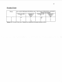
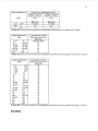
Niveaux d'essai
Sur l'accès d'alimentation de puissance, PE
Niveau
Tension de crête
kV
Fréquence de
répétition
Sur les signaux Entree/Sortie, les acces de
données et de contrble
Tension de crête
Fréquence de
kV
répétition
IrHz
IrHz
1
035
2
3
4
1
2
4
I
5
5
5
225
0,25
5
5
5
035
1
2
I
5
Annexe B
Tableau B . l - Conseils pour le choix des niveaux d'essais
Humidité relative
pouvant descendre
jusu'à
Classe
I
I
1
2
3
4
YO
Matériaux
antistatiques
Matériaux
synthétiques
I
35
10
50
10
2
X
X
X
X
l a - Décharge au contact
Niveau
Tension d'essai
l b - Décharge dans l'air
Niveau
Tension d'essai
kY
1
2
3
4
Tension maximale
2
4
6
8
1
2
3
4
kV
2
4
8
15
Annexe C
Contenu des fichiers CEM et des programmes dans le générateur de salves.
Dans les pages suivantes sont montrés les réglages préprogrammés du logiciel pour mesurer l’émission et du
générateur de salves.
43
4
Réglages du générateur de salves:
V-nominal
Polarity +/Trigger A/M
burst ourput:
e to Hv-out
0
to line 1phase
0
to line 3 phase
1 ph coupling path:
?a& L
Path N
Path PE
Path L+N
Path L+PE
Path N+PE
Path L+N+PE
Spike freq.
Burst dur.
Burst freq.
Test time
Random spikes
Burst syncro
Syncro freq.
Syncro angle
No transition
Voltage trans
Freq. trans
Syncro trans
Pïûg-A
0.500 kV
POS
AUTO
NEG
AUTO
Prog-C
0.500 kV
POS
AUTO
Prog-B
0.500 kV
...
...
YES
YES
YES
...
...
...
...
ON
ON
ON
OFF
OFF
OFF
UN
ON
ON
OFF
OFF
OFF
OFF
OFF
5.00 kHz
15.0 ms
3%
60 s
OFF
ON
50 Hz
90"
activ
5.00 kHz
15.0 ms
3Hz
60 s
OFF
UN
50 Hz
270"
activ
5.00 kHz
15.0 ms
3Hz
60 s
OFF
OFF
50 Hz
.....
.....
.....
.....
.....
.....
.....
46
Annexe D
Limites d’émission pour les equipements sous test
EN 55011
Limite maximale de rayonnement
Gamme de fréquences
Fréquence centrale
Mhz
Mhz
6,765 6,780
6,795 Á i’étude
13,560
13,553 13,567 Sans restriction
26,957 27,283 Sans restriction
27,120
40,66
40,70 Sans restriction
40,680
433,920
433,05
- 434,79 À I’étude
2400
- 2500
2450
Sans restriction
5725
- 5875
5800
Sans restriction
24000
- 24250
24125
Sans restriction
61000
- 61500
À l’étude
61250
122500
122000
- 123000
À l’étude
À l’étude
244000
- 246000
245000
rableau D.l: Fréquences désignées par I ’UIT commepéquences fondamentales pour es appareils ISM.
Bande de fiéquences
Groupe 1
En quasi-crête En valeur moyenne
MHZ
0,15
0,50
5
~
-
79
73
73
0,50
5
30
66
60
60
Groupes 1et 2
En quasi-crête
66
56
Décroissant avec le
Décroissant avec le
logarithme de la
logarithme de la
fiéquence jusqu’à
fréquence jusqu’à
Bande de fréquences
MHZ
0,15 - 0,50
46
56
I
0.50
5
-5
- 30
Groupe 2
En quasi-crête
En valeur
moyenne
100
90
86
76
80
90
Décroissant
avec le
Décroissant avec le
logarithme de la
logarithme de la
fréquencejusqu’à fréquence jusqu’à
70
60
I
56
60
I
46
50
I
47
Bande de fi-équences
MHZ
0.15
0,50
5
- 0.50
-5
- 30
Groupe 1 Classe A
Distance de mesure
30 m
Groupe 1 Classe B
Distance de mesure
10 m
dB(pV/m)
A l’étude
dB(pV/m)
A l’étude
37
37
Tableau D.4: Limites du rayonnement électromagnétiqueperturbateurpour les appareils du Groupe 1
Bande de fréquences
MHZ
0,15
30
80,872
81,848
134,786
136,414
230
-
30
80,872
81,848
134,786
136,414
230
1000
Bande de fréquences
MHZ
0,15
0,49
1,705
2,194
3,95
20
30
47
68
80,872
81,848
87
134,786
136,414
156
174
188’7
190,979
230
400
470
-
-
EN 55022
0,49
1,705
2,194
3,95
20
30
47
68
80,872
81,848
87
134,786
136,414
156
174
188,7
190,979
230
400
470
1000
Limites pour la Classe B
Distance de mesure 10 m
A
Limites a l’étude
30
50
30
50
30
37
Limites pour la Classe A
Distance de mesure 30 m
dB( pV/m)
85
75
80
75
60
50
58
40
53
68
53
50
60
50
64
40
50
40
50
53
50
48
Gamme de fréquences
Quasi-crête
Valeur mo enne
0,5
à 30
73
60
Tableau D.7:Limites des perturbations conduites aux bornes d’alimentation pour les ATI de Classe A
I
Gammedefréquences
I
Limites
dB(c1v)
Quasi-crête
Valeur moyenne
I
I
Mhz
56
46
à 5
60
50
5
à 30
Tableau D.8:Limites des perturbations conduites aux bornes d *alimentationpour ,,s ATI de Classe B
035
1
Gamme de fréquences
Mhz
30 à 230
230 à 1000
Gamme de fréquences
Mhz
30 à 230
230 a 1000
I
Limiles quasi-Crete
dB (ClV/In)
40
47
Limites quasi-Crete
dB (pV/m)
30
37
I
Tu Eindhoven / ICAM-Nantes, July 1996
The set up of a measunng platform for EMC
Annex B: The details of the test-equipment
The details of the test-equipment are given in Table B. 1.
Name of apparatus
Manufacturer
Type
Haefely Trench A.G.
Burst Tester, EFT / Burst Generator PEFT Junior
HF-Coupling Clamp
IP4A
Haefely Trench A.G.
Eiectro Discharge Tester
PESU i600
Haefely Trench A.G.
Spectrum Analyser
SA450B
Laplace Instruments LTD
Computer Interface
SA1030
Laplace Instruments LTD
E & H near field probes
RF100
Laplace Instruments LTD
Log-Periodic Antenna
RF200
Laplace Instruments LTD
Pre-amplifier
SA1020
Laplace Instruments LTD
LISN
LISN1600
Thurlby Thandar Instruments Limited
Isolation Transformer
Type: Mono, No 8498 BRC Transformateurs
Cage of Faraday
Amplisilence
Sispe
Table B.1.
All this equipment is bought by:
~
DICOMTJZCH
Ringablach
56400 Plumergat
Tel: (33) 97 56 13 14
Fax: (33) 97 56 13 43
- 69 -
TU Emdhoven / ICAM-Nantes, July 1996
The set up of a measuring platform for EMC
Literature
Catalogue Radialex, département Anitparasitage et Compatibilité Electromagnétique, Radialex, Villeurbanne
(France), 1996.
Charoy, Alain, Compatibilité Electromagnétique: Parasites et perturbations de électroniques Partie 2/3/4,
Dunod, Paris, 1992.
Les fabricants n’ontplus le choix, les labos font leplein, MESURES 684, April 1996, p. 35-41.
Ministère de i’hdustrie, des Postes et Télécommunicaîionet du Commeree Exteriem-,La libie circulation des
produits en Europe ?, Paris, 1995.
UTE (Union Technique de l’Electricité), Compatibilité Electromagnétique CEM Réglementation et
normalisation, Evaluation et attestation de la confomité, UTE, Paris, January 1996
Williams, Tim, EMC for Product Engineers, Buttenvorih-Heinemann, Oxford, 1995, Tdedition.
- 70 -