1
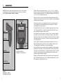
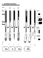
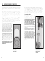
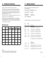
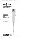
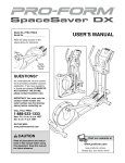
EDP
™
Electronic Pipette
Six pipettes for
volume ranges from
0.5 µL to 2.5 mL
100 µL model shown
Rainin Instrument, LLC
7500 Edgewater Drive, Box 2160
Oakland, CA 94621-0060
www.rainin.com
PI-17 R1 WEB
Foreword
For best results, read this manual completely before using your EDP Electronic Pipette.
WARNING:
This equipment generates and uses radio frequency energy and if not installed and used
properly, i.e., in strict accordance with the instructions manual, may cause harmful interference to radio communications. It has been tested and found to comply with the limits
for a Class A computing device pursuant to Subpart J of Part 15 of FCC Rules, which are
designed to provide reasonable protection against such interference when operated in a
commercial environment.
Operation of this equipment in a residential area is likely to cause interference, in which
case the user at his own expense will be required to take whatever measures may be
required to correct the interference.
Prices and specifications are subject to change without notice. “EDP”, “RAININ Certified”
and “Clean-Pak” are trademarks of Rainin Instrument, LLC. EDP Pipettes are manufactured under U.S. Patent Nos. 4,671,123. Other U.S. and national patents issued and
pending. Copyright 1984-2003, Rainin Instrument, LLC.
CONTENTS
1.0
DESCRIPTION ................................................................2
2.0
UNPACKING INSTRUCTIONS ............................................4
3.0
INSTALLING PORTABLE POWER PACK ..............................5
4.0
LIQUID MEASUREMENT MODES........................................6
5.0
QUICK REFERENCE: GENERAL ........................................7
6.0
QUICK REFERENCE: PIPETTE MODE ................................8
7.0
QUICK REFERENCE: MULTIDISPENSE MODE ....................10
8.0
QUICK REFERENCE: TITRATE MODE................................12
9.0
QUICK REFERENCE: DILUTE MODE ................................14
10.0
QUESTIONS AND ANSWERS ..........................................16
11.0
CHARGING THE POWER PACK ......................................23
12.0
DISPOSABLE TIPS ........................................................25
13.0
HINTS FOR PROPER PIPETTING ....................................27
14.0
CHANGING LIQUID ENDS ..............................................29
15.0
REMOVING THE TIP EJECTOR ........................................31
16.0
CARE AND CLEANING OF LIQUID ENDS ..........................32
17.0
TROUBLESHOOTING .....................................................35
18.0
PERFORMANCE SPECIFICATIONS....................................36
19.0
ORDERING INFORMATION..............................................37
20.0
WARRANTY INFORMATION ............................................39
1.
DESCRIPTION
RAININ EDP Electronic Pipettes measure liquid volumes from one to 2500 microliters
accurately and precisely. Volume measurements may occur in any of four different
modes: PIPETTING, DISPENSING, TITRATING, and DILUTING.
Six EDP models have nominal volume ranges of 10, 25, 100, 250, 1000, and 2500
microliters, respectively. Actual volumes are adjustable and may be changed rapidly and
effortlessly by simple keyboard entries. The recommended working range for each model
is 10% to 100% of the nominal volume range.
Each model consists of an electronic drive module and a replaceable liquid end. All six
models incorporate the same electronic drive module. The liquid ends are interchangeable
and may be purchased separately.
Encoder Plug
Each liquid end contains a precisely machined and polished chrome-plated stainless
steel piston which moves up and down during volume measurements. The distance
moved determines the volume measured.
Display
Trigger
The drive module controls the movement of the piston. Power for movement is supplied
by a special electronic linear actuator. An on-board microcomputer-on-a-chip monitors
the position of the piston and sends commands to the actuator. The position of the piston
at the beginning and end of each stroke is controlled solely by the microcomputer. There
are no mechanical stops.
Drive Module
Keyboard
Tip Ejector
Button
Liquid End
The chamber below the piston connects to a disposable polypropylene tip via a column
of air. The disposable tip is the only part of the instrument touching the liquid. Tips are
easily changed between samples to avoid carryover.
FIGURE 1.2
ENCODER PLUG, DISPLAY,
KEYBOARD, TIP EJECTOR BUTTON
The microcomputer communicates operating parameters and status to the user via a
liquid crystal display and a tone generator. It receives commands from the user via a
13-key keyboard and is activated by a convenient pistol-grip trigger.
Power for the EDP pipette can be supplied either via a lightweight cord from a miniature
wall transformer power supply or, for fully portable operation, from the optional Portable
Power Pack accessory which mounts in a compartment in the drive module. The Portable
Power Pack can be recharged by connecting the wall transformer. The pipette can be
operated from the transformer while charging.
Alternately, the EDP pipette with Portable Power Pack installed can be recharged by placing it on the Rapid Charge Stand accessory. The Rapid Charge Stand provides a convenient resting place for the pipette when not in use.
Disposable Tip
FIGURE 1.1
DRIVE MODULE, TRIGGER,
LIQUID END, DISPOSABLE TIP
2
3
2.
UNPACKING INSTRUCTIONS
In addition to this instruction manual, the EDP package should contain
1. The EDP Electronic Pipette
2. The wall transformer
Carefully remove each part from the package and inspect for shipping damage. If any part
appears to have been damaged in shipment, a damage claim should be filed immediately with the shipping carrier. Rainin Instrument LLC can assist you in filing a claim.
Be sure to save the shipping container and all packing materials until the instrument has
been checked out and found to function properly.
To operate the EDP pipette, first plug the wall transformer into a convenient power outlet
(105–130 volt, 50–60Hz or 210–260 volt, 50–60Hz, matching the specification printed
on the transformer). Then plug the power cord from the transformer into the receptacle
provided on the back of the EDP drive module.
As power is connected, you should feel the drive module begin to purr and move. The
instrument will execute an initialization routine to properly position the piston for liquid
measurement. The movement will stop after about 8 seconds, and the instrument will be
silent. At this time, the digital volume display on the LCD panel should become visible.
Should these initial events fail to occur, consult the troubleshooting information in Section
17 of this manual.
3.
INSTALLING PORTABLE POWER PACK
When you are ready to install the Portable Power Pack, first disconnect the transformer
cord from the instrument. Then remove the cover from the power pack compartment. The
compartment is located at the rear of the drive module next to the power cord receptacle.
Plug the cord on the Power Pack into the cord from the pipette, which you should have
found inside the compartment. Be careful to connect the two halves of the plug in the
proper orientation. The plug is designed so that it can only be connected one way.
Improper connection could result in damage to either the Power Pack or the EDP pipette.
When the Power Pack is connected, the instrument should purr, move, and execute the
8-second initialization sequence exactly as it did when power was first applied from the
wall transformer. If this does not occur but the pipette was operating properly when
powered by the wall transformer, the Power Pack may have discharged during storage
and transit. See Section 11 of this manual for recharging instructions.
Fold the cord so that the plug is positioned neatly on top of the Portable Power Pack.
Slide the Power Pack into the compartment with the excess cord to the right as shown
in Figures 3.1 and 3.2.
Once the Power Pack has been installed and fitted snugly in its compartment on the
EDP drive module, replace the compartment cover.
Attach a disposable tip to the liquid end by pressing the shaft into the tip with a firm twisting motion.
The EDP pipette is now ready for use.
NOTE:
If you have purchased the optional Portable Power Pack accessory, the Power Pack may
be installed in the EDP drive module and the instrument can then be operated without the
power cord attached. Before installing the Power Pack, it is a good idea to operate the
EDP pipette under power from the wall transformer a few times to be sure that everything
is functioning properly.
FIGURE 3.1
POSITION PLUG ABOVE
POWER PACK
4
FIGURE 3.2
POSITION EXCESS CORD
TO THE RIGHT
5
4.
LIQUID MEASUREMENT MODES
5.
QUICK REFERENCE: GENERAL
KEYBOARD DISABLED
The EDP Electronic Pipette can operate in four distinct liquid measurement modes,
described in Table 4.1.
DISPENSE
When power is first applied, or after changing the liquid end, the EDP pipette defaults to
the PIPETTE mode.
The mode may be changed whenever the keyboard is active. The keyboard is active when
the symbol “KB” is visible at the lower left of the display and the word “locked” is absent.
If the keyboard is not active, see Section 5.
PRESS
To change the mode, press the FUNCTION key F followed by the appropriate numeric key
as indicated in Table 4.1.
F
C
O
KEYBOARD ENABLED
PICKUP
Table 4.1
MODE
#1) PIPETTE
#2) MULTIDISPENSE
#3) TITRATE
#4) DILUTE
KB
DESCRIPTION
A single volume of liquid is
aspirated, then dispensed.
TO SET
DISPLAY SHOWS
P
Press F 1
A single volume of liquid (V1)
is aspirated, then partially
dispensed stepwise as a series
Press F
of equal but smaller volumes
(V2).
A single volume of liquid (V1)
is aspirated, then partially
dispensed under user control.
A smaller volume (V2) may be
specified to be dispensed
Press F
immediately. During dispensing, the display shows the total
volume dispensed.
KEYBOARD LOCKED
(blank)
PICKUP
M
2
KB locked
M
PRESS
T
3
Two separate volumes (V1, V2)
of different liquids are aspirated
sequentially, separated by a
D
small air segment. Both liquids
are dispensed together. Volume Press F 4
V1, the diluent, is usually larger
than volume V2, the sample.
F
L
9
PRESS
F
L
9
PRESS
F
8
KEYBOARD UNLOCKED
T
PICKUP
KB
AUDIBLE TONES ON
D
PRESS
F
8
AUDIBLE TONES OFF
Keyboard entries other than those shown on this page will be accepted only when the
keyboard is enabled and unlocked.
6
7
6.
QUICK REFERENCE: PIPETTE MODE (#1)
OPERATION:
READY
PICKUP
DISPENSE
READY
BLOWOUT
PISTON
POSITION:
TO SET MODE
UP
Press
F
P
1
TO SET VOLUME
Press 1 5 . 0
E
(Desired volume)
HOME
DOWN
TO CLEAR, EMPTY,
OR RETURN HOME
Pull
Pull
trigger
trigger
Press
after
pause
after
pause
F
C
0
Holding
trigger in
delays
this step.
Display
and
Tone
beep
PICKUP
beep
beep
beep
DISPENSE
KB
8
9
7.
QUICK REFERENCE: MULTIDISPENSE MODE (#2)
OPERATION:
DISPENSE
V2
PICKUP
V1
READY
DISCARD
REMAINDER
BLOWOUT
READY
PISTON
POSITION:
TO SET MODE
UP
Press
F
M
2
TO SET NEW VOLUMES
V1: Press 1 0 0 0
Repeat
E
(Desired pickup volume)
HOME
V2: Press 2 1 0
DOWN
E
(Desired dispense volume)
Pull
Pull
Pull
Pull
trigger
trigger
trigger
trigger
TO RE-ENTER SAME VOLUME
after
pause
V1: PRESS E
V2: PRESS E
Holding
trigger in
delays
this step.
TO CLEAR, EMPTY,
OR RETURN HOME
Press
Display
and
Tone
beep
PICKUP
M
KB
10
V1
beep on last
DISPENSE
M
beep
beep
F
C
0
beep
beep
DISPENSE
V2
M
11
8.0
QUICK REFERENCE: TITRATE MODE (#3)
OPERATION:
DISPENSE
V2 +
PICKUP
V1
READY
DISCARD
REMAINDER
BLOWOUT
READY
PISTON
POSITION:
TO SET MODE
UP
Press
F
T
3
TO SET NEW VOLUMES
V1: Press 1 0 0 . 0
E
(Desired pickup volume)
HOME
V2: Press 1 5 . 7
DOWN
Pull
Tap
or
hold
Hold
Pull
trigger
trigger
trigger
trigger
E
(Desired initial
dispense volume)
after
pause
TO RE-ENTER SAME VOLUME
V1: PRESS E
V2: PRESS E
Holding
trigger in
delays
this step.
TO CLEAR, EMPTY,
OR RETURN HOME
Press
Display
and
Tone
beep
PICKUP
T
V1
read volume
dispensed
beep
beep
F
C
0
beep
beep
DISPENSE
T
KB
12
13
9.
QUICK REFERENCE: DILUTE MODE (#4)
PICKUP
DILUENT
V1
OPERATION:
READY
PICKUP
SAMPLE
V2
PICKUP
AIR
DISPENSE
BLOWOUT
READY
PISTON
POSITION:
TO SET MODE
UP
Press
F
D
4
TO SET NEW VOLUMES
V1: Press 9 0 . 0
E
(Desired diluent volume)
HOME
V2: Press 1 0 . 0
DOWN
E
(Desired sample volume)
Pull
Pull
Pull
Pull
trigger
trigger
trigger
trigger
after
pause
TO RE-ENTER
SAME VOLUME
after
pause
V1: PRESS E
V2: PRESS E
Holding
trigger in
delays
this step.
TO CLEAR, EMPTY,
OR RETURN HOME
Press
Display
and
Tone
beep
PICKUP
D
KB
14
V1
beep
beep
PICKUP
D
beep
PICKUP
D
F
C
0
beep
beep
DISPENSE
V2
D
15
10.
QUESTIONS AND ANSWERS
Q #1:
Is it necessary to enter the decimal point when setting a volume?
Q #4:
What happens if no encoder plug is present?
A:
No. If the volume is a whole microliter, the decimal point and zeros following it need not
be entered. In fact, with the nominal 1000 and 2500 microliter instruments, all possible
volume settings are whole microliters, and the decimal point is not displayed. If the decimal point is pressed when setting a volume on either of these instruments, all following
digits will be ignored.
A:
If the keyboard is not locked the numeric display will show “– – –” and the instrument will
not operate. If the keyboard is locked, the instrument will behave as if the previously present encoder plug were still in place.
Q #2:
What is the smallest possible increment in a volume setting?
A:
For 10, 100, and 1000 microliter instruments, the smallest possible increment in a
volume setting is 1/1000 of the nominal range of the instrument. For 25, 250, and
2500 microliter instruments, the smallest increment is 1/500 of the nominal range. With
the 25 microliter instrument volume settings are rounded down to the next lower 0.00 or
0.05 microliter. With the 250 microliter instrument volume settings are rounded down to
next lower 0.0 or 0.5 microliter. The 2500 microliter instrument rounds down to the next
lower multiple of 5 microliters.
Q #3:
Since all EDP models have the same electronic drive module, how does the drive
module know the nominal volume of the liquid end attached?
A:
The encoder plug in the head of the drive module must match the liquid end. It is the
user’s responsibility to verify this. Whenever the liquid end is changed, the encoder plug
must also be changed. A good way to check for the correct volume is to observe the LCD
display following the 8-second initialization sequence after the encoder plug is inserted.
The numeric display should show the nominal volume of the liquid end.
NOTE:
If the EDP instrument is to be operated at a single volume setting for a large number of
tests, this feature can be used to ensure that the volume setting can not be accidentally
changed. Simply set the volume desired. Then lock the keyboard, remove the encoder
plug, and store it in a safe place. The instrument will operate properly only at the previously set volume. If the keyboard is unlocked, the instrument will not function until the
encoder plug is reinserted.
Q #5:
Does the EDP pipette remember volumes?
A:
Yes. Once a volume setting has been specified in any of the four operating modes, that
setting will be remembered and used until it is changed by keyboard entries from the
user. For example: An instrument in the PIPETTE mode is set to measure 75 microliters.
The instrument is then used in the DILUTE mode to mix 90 microliters of diluent with 10
microliters of sample. If the instrument is returned to the PIPETTE mode, it will be ready to
again measure 75 microliters without further keyboard entries. When the instrument is
next placed in the DILUTE mode, it will still be set to aspirate 90 microliters of diluent and
10 microliters of sample.
This retention of previous volume settings applies to every mode, regardless of how many
other modes have been used in between, as long as power has been applied to the
instrument continuously and the encoder plug has not been removed. Removing power
from the instrument will result in loss of volume settings from memory. The instrument will
initialize to its default values when power is restored.
WARNING:
When changing the encoder plug, the keyboard must be “unlocked.” Removing or
changing the encoder plug when the keyboard is locked has no effect, and could result in
measurement errors if a different liquid end has been attached.
16
17
Q #6:
What does it mean when the volume indicator on the display is flashing?
A:
If the keyboard is enabled (symbol “KB” showing at lower left of display), a flashing
volume display means a volume entry is in progress or is being called for. In modes
requiring two volumes, the symbol “V1: or “V2” at the right of the display tells you which
volume is being called for. The volume entry sequence must be completed before the
instrument can be used for measurements.
Q #7:
How can an erroneous volume entry be corrected?
A:
If the “enter” key has already been pressed and you are in the PIPETTE mode, simply
repeat the volume entry with the correct volume. If you are in any mode other than the
PIPETTE mode, press the “enter” key a second time, then repeat the volume entry.
If the “enter” key has not yet been pressed when you discover your mistake, pressing the
sequence F 0 clears the erroneous entry and causes the display to flash the previous
volume setting. The correct volume can now be entered.
Q #8:
What happens if the volume entered is an illegal value?
A:
The instrument will emit a warbling sound, the volume display will show the message
“Err” for approximately one second, and the illegal volume will not be accepted. The user
must proceed by entering a legal value.
WARNING:
In the MULTIDISPENSE and TITRATE modes, a possible trap exists if V1 has been inadvertently set to a very small value, especially if the user cannot remember what value was
entered for V1. In this case, almost any value for V2 will be illegal and the drive module
will repeatedly give the error signal for every volume entered. If this situation should
occur, it can best be corrected by entering the smallest possible value for V2. The smallest possible value would be 1/1000 of the nominal full scale volume (1/500 for 25,
250, and 2500 microliter instruments). The display should now return to V1, and permit
a legal volume entry sequence to be executed.
The same difficulty may occur in the DILUTE mode if the value entered for V1 is very close
to the nominal full-scale volume of the instrument. The solution is the same: Enter the
smallest possible value for V2 to escape, then enter the desired legal values for V1
and V2.
Q #9:
How do I know when the Power Pack needs recharging?
A:
The instrument will intermittently warble and display the message “Lob” on the volume
display. When this occurs, the Power Pack should be recharged by placing the instrument
on the Rapid Charge Stand or by attaching the wall transformer. If the wall transformer is
used, operation of the instrument may continue with the cord attached.
In no case should the instrument continue to be operated without recharging when the
low battery signal arises, since accurate measurements cannot be guaranteed under
these conditions. Also, if the charge on the Power Pack becomes sufficiently low, an
initialization sequence may occur. In this event, any stored volume specifications will
be lost and must be re-entered.
The following volume entries are illegal:
(1) Any volume greater than the nominal full-range volume.
(2) Zero, or any volume less than the smallest incremental volume.
(Exception: In the TITRATE mode, zero is a legal value for V2.)
(3) In the MULTIDISPENSE and TITRATE modes, any volume V2 greater than V1.
(4) In the DILUTE mode, any volume V1 or V2 which causes the sum
V1 + V2 to exceed 101% of the nominal full-range volume.
Q #10:
What does it mean if I try to enter a volume and nothing happens?
A:
Normally, you will know that the EDP drive module is accepting a volume entry because
the digital volume indicator begins to flash as soon as the first numeric key is pressed. If
this does not occur, it is probably because the keyboard is locked or the keyboard is not
enabled. Check the lower left portion of the display for the letters “KB” and the absence of
the word “locked.” See Section 4 for toggling procedures.
Continued ...
18
19
The keyboard lock is for protection. When the EDP pipette is used to repeat the same
program over a long period of time, locking the keyboard eliminates the possibility of
unwanted volume or mode changes.
Q #11:
Why should the last aliquot be discarded in the MULTIDISPENSE mode?
A:
If V1 is not a perfect multiple of V2, then the final aliquot will be smaller than all the rest.
Also, even if V1 is a perfect multiple, the last aliquot will be less accurate than all the
others.
Q #12:
How do I know when I have reached the last aliquot in a MULTIDISPENSE sequence?
A:
When the next-to-last aliquot has been dispensed, the tone generator will beep, and the
symbol “V2” will disappear from the right side of the display. If the last aliquot is smaller
than all the others, the volume indicator will change to display this smaller volume. The
last aliquot is normally discarded.
Q #13:
What happens when I dispense in the TITRATE mode?
In titrating to an endpoint, it is always best to dispense with the end of the disposable tip
actually immersed 2-3 mm into the liquid in the receiving vessel. This promotes immediate mixing and avoids endpoint errors.
Q #14:
How can I empty the remaining liquid from the tip rapidly after dispensing only a
portion of the aspirated volume in the MULTIDISPENSE or TITRATE mode?
A:
Press the key sequence F 0 . This will cause the piston to immediately move down,
emptying the tip. Then after a brief pause, the instrument will execute a blowout cycle,
and the piston will return to the home position and be ready to pick up the next sample.
Q #15:
What is the purpose of the air segment in the DILUTE mode?
A:
It prevents contamination of the sample in its original container by diluent. If you wish,
you can wipe the outside of the tip after the air segment stroke before aspirating the
sample.
A:
First, if a non-zero value was set for V2, the V2 symbol will appear on the volume indicator and this volume will be dispensed quickly the first time the trigger is pulled.
Q #16:
Can the EDP pipette be used for “reverse-mode” pipetting of serum, plasma, and other
liquids of moderate viscosity?
Next, or if V2 was zero, pulling the trigger will cause the piston to start moving downward
slowly. If the trigger is held in, the rate of movement of the piston will accelerate gradually, increasing the rate at which liquid is dispensed, until a maximum rate is reached.
You can feel this in the movement of the actuator as you operate the pipette.
A:
Yes. Use the MULTIDISPENSE mode with V1 set to a slightly higher volume than desired,
and V2 set to the desired volume. The pickup cycle will then aspirate a slight excess of
liquid. The first press of the trigger in the dispense cycle will dispense the desired volume.
The second press will dispense the excess, to be discarded. The third press will initiate
the blowout cycle and return the piston to the home position.
If the trigger is released, then pressed again, the sequence of events repeats. First slow
movement, then gradual acceleration to a maximum. This allows you to approach an
endpoint rapidly by holding the trigger, or very gradually by tapping the trigger so that the
piston always moves downward very slowly.
20
At all times during the dispense cycle, the volume display records the total volume
dispensed.
21
11.
CHARGING THE POWER PACK
Q #17:
Can the EDP pipette be used to measure the volume of liquid in a container?
Operating the EDP Electronic Pipette with the Portable Power Pack installed provides
maximum freedom of movement and ease of use.
A:
Yes, if you know approximately how much liquid is present. Place the EDP pipette in the
TITRATE mode and set V1 to the approximate volume and V2 to zero. Now pick up the
liquid in the container.
At the option of the user, the EDP pipette may also be operated with the Power Pack
removed and the wall transformer connected. This has the advantage of providing a slight
reduction in weight, which may be desirable for long uninterrupted liquid measurement
procedures. However, portability is limited, and operating the pipette with the cord
attached requires more care and coordination. Also, any interruption of line current when
operating without the Power Pack will cause all stored volumes to be lost from memory.
The pipette will execute the 8-second initialization sequence when power is restored.
Any liquid held in the tip at the time power is interrupted will be dispensed during the
initialization sequence. For these reasons, operation with the Power Pack installed
is recommended.
If all the liquid was not picked up, the volume approximation was too small. Dispense the
liquid back into the container, reset V1 to a higher approximate volume, and try again.
If all the liquid was picked up, check the tip to see if there is an air segment below the
liquid. Hold or quickly squeeze and release the trigger until the air has been expelled and
the liquid in the tip just reaches the orifice. Read the volume indicator and subtract this
reading from V1 to get the actual volume of liquid present. After taking the reading, hold
the trigger or press F O to return the liquid in the tip to the container.
With the Power Pack installed, the electronic drive module should always be connected
to a charger when not in use. This will assure that the Power Pack is well charged and
minimize instances of discharge during use.
If the instrument will be stored without using for an extended period, the Power Pack
should be fully charged and then removed. This will prevent discharge during storage.
Whenever the Power Pack is installed, the drive module is “on”. Even though the actuator
is not moving the piston, there is a continuous small power consumption by the microcomputer electronics.
If the Power Pack becomes discharged during operation of the instrument, the drive
module will emit an audible warble and the message “Lob” will appear in place of the
volume on the numeric display. Whenever this occurs, the instrument should be attached
to a charger immediately after completing the current pipetting cycle. If the wall transformer is used, operation of the instrument may continue without interruption after a few
seconds.
The Portable Power Pack can only be recharged while it is installed in an EDP drive
module.
22
23
12.
DISPOSABLE TIPS
Recharging is Simple:
The requirements for disposable pipette tips are fairly demanding.
With the wall transformer, simply plug the transformer
cord into the receptacle on the drive module. Be sure
the transformer is plugged into an active AC receptacle which supplies power matching the specification
on the charger (105–130V, 50–60Hz for domestic
models). A totally discharged Power Pack will be
completely charged in approximately 14 hours.
Tips must seal properly on the EDP shaft and must be flexible and smooth on their interior surfaces so that the shaft is not damaged.
A more elegant way to charge the EDP Power Pack is
to use the accessory Rapid Charge Stand. The Stand
provides a convenient resting place for the EDP
pipette. Whenever the instrument is placed on the
stand, charging occurs automatically via the special
external contacts on the sides of the drive module.
While the instrument is being charged on the Stand,
the symbol “FC” will appear on the display, and all
functions are inoperative. Operation may be resumed
as soon as the instrument is removed from the Stand
Tips must be free of flash and particulates. Microscopic flash at the orifice can limit precision and accuracy by causing unwanted retention of liquid by the tip. Also, the orifice
must be the correct size and consistent in size and geometry from tip to tip.
Both interior and exterior surfaces must be clear, smooth, and hydrophobic to avoid
unwanted retention of liquid as droplets or film which can reduce accuracy and reproducibility.
FIGURE 11.1
CONNECTING THE
WALL TRANSFORMER
Seal
The Rapid Charge Stand delivers current to the Power
Pack much more rapidly than the wall transformer. A
totally discharged Power Pack can be completely
charged in 1-1/2 hours. Special circuitry in the Stand
meters current and monitors the temperature of the
Power Pack battery via a temperature probe contained
in the Power Pack itself. The Stand delivers current
under carefully controlled conditions which assure
that damage to the Power Pack will not occur.
Surface
RAININ EDP Electronic Pipettes are designed and calibrated for use with RAININ Certified™ Disposable Tips.
Performance to specification by EDP Pipettes is guaranteed only when RAININ Certified Tips are used as recommended. Rainin Instrument LLC accepts no responsibility
for damage to EDP Pipettes or for poor liquid measurement performance resulting from use of non–standard
pipette tips of inferior quality.
RAININ Certified Tips are molded from the highest quality
virgin polypropylene plastic. Only the finest molds and
the best possible molding procedures are used. Molds
are inspected and maintained regularly to assure conformance with high quality standards. Samples from each
lot of tips are inspected microscopically to assure that
every lot meets these standards.
When the Power Pack is fully charged, the red “rapid
charging” light goes off and the Rapid Charge Stand
delivers a small maintenance current that allows the
EDP pipette to be safely left on the stand for as long
as desired.
Orifice
FIGURE 12.1
RAININ CERTIFIED TIP:
SEAL, SURFACE, ORIFICE
FIGURE 11.2
RAPID CHARGE STAND WITH
EDP PIPETTE IN PLACE
24
25
Tips for use with EDP are:
13.
Model
EDP-10
EDP-25
EDP-100
EDP-250
EDP-1000
EDP-2500
Maximum
Volume
10 µL
25 µL
100 µL
250 µL
1000 µL
2500 µL
Bulk Tip
Cat. No.
RC-250
RC-250
RC-250
RC-250
RC-1000
RC-2500
Rack Tip
Cat. No.
RT-250
RT-250
RT-250
RT-250
RT-1000
RT-2000
Presterilized
Tip Cat. No.
SpaceSaver
Cat. No.
RT-250S
GPS-250
RT-250S
GPS-250
RT-250S
GPS-250
RT-250S
GPS-250
RT-1000S
GPS-1000
RT-2000S
n/a
Green-Pak
Cat. No.
GP-250
GP-250
GP-250
GP-250
GP-1000
n/a
StableStak
Cat. No.
SS-250
SS-250
SS-250
SS-250
n/a
n/a
StableRak
Cat. No.
SR-250
SR-250
SR-250
SR-250
n/a
n/a
HINTS FOR PROPER PIPETTING
EDP Electronic Pipettes are calibrated to deliver accurate volumes under the following
conditions:
1. The liquid pipetted is water or any liquid with a density not significantly different from,
a viscosity not significantly greater than, and a vapor pressure not significantly
greater than that of water.
2. The temperature of the room, the pipetting instrument, and the liquid are all in the
range 21.5°C ± 1°C.
3. The pipette is kept vertical during pipetting. During aspiration of sample the end of the
disposable tip should be immersed 2 to 3 mm below the liquid surface.
4. There is no significant adherence of liquid to the surfaces of the disposable tip during
pipetting. Each tip should be rinsed once before pipetting to assure the best accuracy.
5. The pipette tip is touching the wall of the receiving vessel during dispensing. The tip
should be moved along the wall at the end of each dispensing step to remove any
excess liquid outside the tip.
EDP Electronic Pipettes remove many of the operator variables from the pipetting process.
Inaccuracies due to human error in locating the exact stop positions at the end of the
piston stroke or in releasing or pressing the pushbutton too fast or too slow do not exist.
So long as the above conditions apply, most operators will be able to obtain accurate
and precise liquid measurements.
Even when conditions differ from the ideal, EDP pipettes can produce good liquid measurements. With liquids much denser than water, for example, the actual volume measured
will be less than the setting on the pipette, but consistency from sample to sample will
still be excellent. If absolute accuracy is important, the volume error can be compensated
by applying a correction factor to the volume setting.
Continued …
26
27
14.
Liquids of viscosity moderately higher than water, such as serum and plasma, can be
measured accurately by using the reverse-mode pipetting strategy to aspirate a larger
volume than is dispensed. (See Section 10, Question #16.) By pipetting in reverse-mode,
residual liquid on the interior wall of the disposable tip becomes a less important factor in
determining volumetric accuracy.
Warm and cold liquids can be measured with good accuracy and precision as long as a
consistent pipetting rhythm is maintained from sample to sample in order to minimize
differences in heating and cooling effects within the pipette. A new disposable tip should
be used with each sample when measuring liquids with temperatures much different from
ambient.
CHANGING LIQUID ENDS
Any of the six available liquid ends can be rapidly mounted on the EDP Drive Module.
To remove the liquid end, first move the EDP pipette to the home position by pressing
F O . The letters “KB” should be visible at the lower left on the display. If the keyboard
has been locked, unlock it.
Now rotate the retainer ring counterclockwise until it is free and pull the liquid end away
from the drive module. Remove the encoder plug from the head of the drive module and
store this with the liquid end. Always disassemble each liquid end, inspect for salts and
residues, and clean if necessary before storing for an extended period.
Maintaining a consistent pipetting rhythm is always a good idea. This will assure the best
reproducibility from sample to sample.
In the MULTIDISPENSE and TITRATE modes, best results are obtained if all dispensing is
performed without delay after aspirating the sample. Delays will exaggerate the effects of
heat transfer if the temperatures of the sample, the instrument, and the room are not
perfectly matched. This will decrease accuracy and precision.
FIGURE 14.3
REMOVING THE
ENCODER PLUG
FIGURE 14.1
ROTATING THE
RETAINING SEAL
FIGURE 14.2
REMOVING THE
LIQUID END
NOTE:
When handling the encoder plug, do not touch the lower surface. Skin oil can contaminate the plug, leading to poor electrical contact and improper function. Should this occur,
the situation can be corrected by swabbing the lower surface of the encoder plug with
isopropanol.
28
29
15.
CAUTION:
When attaching a new liquid end, always install
the liquid end on the drive module before inserting
the encoder plug. If the encoder plug is inserted
while no liquid end is in place, the EDP pipette can
not execute a valid initialization cycle.
Except for the 2500 microliter model, each EDP liquid end has an integral tip ejector, a
movable cylinder surrounding the liquid end and extending up through the retainer ring.
The tip ejector is operated by pressing the tip ejector button on the head of the drive
module.
In certain applications requiring access to liquids in very deep, narrow containers, it may
be necessary to operate the pipette without the tip ejector.
To attach, first hold the liquid end vertical with its
tip resting on a soft surface such as a book or
paper towel. Move the drive module into place
above the liquid end so the actuator pin of the drive
module engages the seat on the piston retainer.
Rotate the liquid end so the tip ejector hole in the
shaft is directly below the tip ejector pin. Be sure
the tip ejector pin passes through the hole. Engage
the keyway in the liquid end with the key on the
drive module. Press the drive module down snugly.
Then thread the retainer ring carefully onto the drive
module and tighten.
To remove the tip ejector, proceed initially as if you
were changing the liquid end. The tip ejector is
held in place by the same threaded retainer ring
which attaches the liquid end to the drive module.
Rotate the retainer ring counter–clockwise and
remove the liquid end from the drive module.
Then slip the retainer ring and the tip ejector off
the shaft.
Leaving the tip ejector spring in place, replace
the retaining ring on the liquid end without the
tip ejector.
NOTE: The 2500 microliter liquid end has no tip
ejector. Just engage the actuator pin, thread the
liquid end carefully onto the drive module, and
tighten. Store the retainer ring and tip ejector spring
for future use with other liquid ends.
Remove the new encoder plug from the package.
Check the labels on the plug and the liquid end
and be sure the volumes match. Plug the encoder
into the receptacle on the head of the drive module.
As soon as the encoder plug is inserted, the EDP
pipette should execute the 8-second initialization
sequence, as if power had just been have been
applied. (NOTE: The keyboard must have been
unlocked for this to occur.)
REMOVING THE TIP EJECTOR
Finally, reattach the liquid end to the drive module.
Note that it is not necessary to remove the encoder
plug from the drive module when removing the tip
ejector. Thus any volume specifications in memory
will be retained.
CAUTION:
Be careful not to press the trigger during
this operation.
FIGURE 14.4
ATTACHING THE LIQUID END
At the end of the initialization sequence, check the display. The instrument should be in
the PIPETTE mode, and the volume indicator should show the nominal full-scale volume of
the liquid end you have attached.
The instrument is now ready for use.
30
FIGURE 15.1
REMOVING THE TIP EJECTOR
FROM THE LIQUID END
31
16.
CARE AND CLEANING OF LIQUID ENDS
For accurate liquid measurement, it is important to maintain the integrity of seals between
the liquid end and the disposable tip and between the piston and the interior of the liquid
end.
Each pipette should be checked periodically for proper sealing: Mount a disposable tip,
set the instrument to its nominal full-scale volume in the PIPETTE mode, and aspirate that
volume of water. Then hold the instrument in the vertical position and observe the tip for
1-2 minutes. During that period there should be no loss of liquid from the tip or droplet
formation at the orifice.
For a proper seal between the liquid end and the tip, it is important to use only RAININ
Certified™ or Clean-Pak™ disposable tips as recommended in Section 12 of this
manual. These tips are designed for proper fit, with sealing surfaces matching the design
of the pipette shaft and proper flexibility to ensure a good seal.
It is important to avoid nicking or scratching the
sealing surface of the pipette shaft. Should the shaft
become scratched and fail to produce an air-tight
seal, this may sometimes be corrected by rotating
the sealing surface of the shaft inside a small piece
of very fine emery cloth. Take care during this
procedure to remove only the minimum amount of
material necessary to restore a proper seal. Should
this measure fail, the shaft should be replaced.
Periodically, the liquid end should be disassembled
for inspection: First remove the liquid end from the
drive module. (It is not necessary to remove the
encoder plug during this procedure.) Now depress
the spring-loaded piston retainer and rotate it
counter-clockwise a fraction of a turn to disengage
the retainer catch. Then pull the piston assembly
out of the shaft. The seal will normally remain
attached to the piston. If the seal is not attached to
the piston, invert the shaft and tap it lightly until the
seal drops out.
Inspect the piston, the seal, and the inside of the
shaft for dirt and particulate contamination, especially salt residues. If any part is not perfectly
clean, remove the contamination by rinsing with a
good solvent such as distilled water or methanol.
The surface of the piston should maintain a high
polish, as when new. If this surface loses its polish
or becomes scratched, corroded, or pitted, seal
wear will accelerate drastically. If any of these
conditions exist, the piston assembly should be
replaced.
The seal between the stainless steel piston and the
interior of the pipette shaft is formed by a self-lubricating PTFE ring and a fluoroelastomer O-ring. The
PTFE ring extends through the O-ring, and only the
PTFE ring contacts the surface of the piston. (See
Figure 16.1) The O-ring actually compresses the
PTFE ring against the piston to maintain a proper
seal even after moderate seal wear. The O-ring itself
also forms the stationary seal between the PTFE
ring and the shaft.
FIGURE 16.1
TYPICAL PISTON
SEAL ASSEMBLY
32
The most important factor in maintaining the integrity of the piston seal is keeping it
clean. Never allow liquid to enter the shaft where it can come into contact with the piston
or the seal. The EDP pipette helps you by controlling the rate of upward movement of the
piston to avoid splashing. In addition, whenever liquid is present in the pipette tip, the
instrument should be held vertically. Never invert the instrument or lay it on its side with
liquid in the tip. Never pull liquid into the shaft by operating the instrument without the
proper disposable tip attached.
FIGURE 16.2
REMOVING THE PISTON
ASSEMBLY FROM THE
LIQUID END
33
17.
TROUBLESHOOTING
Always allow the piston assembly and shaft to dry completely before reassembling. The
piston may be dried with a very soft cloth. However, paper towels or any other material
which may scratch the piston surface should not be used.
The EDP Electronic Pipette is very self-protective. There is actually very little that can go
wrong, assuming proper pipetting techniques are followed and proper care and maintenance procedures, described earlier in this manual, are exercised.
Before reassembling the liquid end, check the piston seal for wear by sliding it along the
piston. The seal should offer a slight but definite resistance to movement on the piston.
The seal should not fall down the piston under its own weight. If no resistance is
observed, the seal should be replaced.
The EDP pipette will not accept volume settings that are outside the allowable range for
each liquid end. However, it is the responsibility of the user to ensure that the proper
liquid end encoder plug is inserted in the control module.
WARNING:
Never apply grease to the seal assembly of an
EDP pipette. The PTFE seal is self-lubricating.
Grease or lubricant residue will alter the effective
diameter of the piston and produce errors in liquid
measurement.
If the Power Pack does not carry sufficient charge for accurate pipetting, the audible tone
will warble and the word “Lob” will appear on the display. If the Power Pack is completely
discharged, the instrument will not operate or emit any sound. Recharge the Power Pack
(See Section 11) before seeking service assistance.
If anything confusing happens during operation of the EDP pipette, this can virtually
always be corrected by clearing the pipette. To clear the pipette, press the key sequence
F O . The piston will return to the home position and the keyboard will be enabled. The
one instance where this will not work is covered in Section 10, Question #8.
Reverse the procedure to reassemble the liquid end.
Make sure the PTFE seal and O-ring are properly
positioned on the piston. Compress the piston
retainer against the piston spring and rotate clockwise to engage the retainer catch. Finally, replace
the liquid end on the drive module. Attach a
disposable tip, and test for proper sealing as
described above.
One more general remedy for confusing problems is to remove power or remove the
encoder plug from the drive module briefly and then replace it. (Be sure the keyboard is
unlocked if you remove the encoder.) This will cause the EDP pipette to reset and go
through the normal 8-second initialization routine. At the end of this routine the instrument
will be in the PIPETTE mode and the volume setting will be the nominal full-scale volume.
The instrument should now function normally. Note that this procedure should be applied
only as a last resort. It has the disadvantage that any existing volume specifications will
be lost from the microcomputer memory and must be re-entered.
2500 MICROLITER LIQUID END:
The piston assembly is threaded into the shaft. Use
the seal wrench (Cat. No. 6100-231) to remove
and replace the assembly as in Figure 16.3.
Reinsertion is most easily done with the shaft
inverted. After tightening with the wrench, push the
piston and release to test for free movement. If the
piston does not return freely, the O-ring and seal
are not properly seated.
EDP pipettes are constructed from the highest quality mechanical and electrical components and designed for trouble-free operation. However, in the event that a real electromechanical malfunction should occur, Rainin Instrument LLC maintains a complete service department to correct the problem. Please call RAININ for instructions regarding
service for your EDP instrument.
FIGURE 16.3
2500 µL LIQUID END
WITH SEAL WRENCH
34
35
18.
PERFORMANCE SPECIFICATIONS
19.
Performance specifications for EDP Electronic Pipettes are of two types:
ACCURACY means the closeness with which the dispensed volume approximates the
volume setting of the instrument. Accuracy is specified as “Mean Error,” the maximum
amount by which the mean value of a large number of replicate measurements of the
same volume will deviate from the set volume. The specification applies to water in the
ambient temperature range of 18°C to 25°C.
PRECISION refers to the “scatter” of individual measurements around the mean of a series
of measurements. It is expressed as standard deviation.
Specifications for precision are always tighter than for accuracy. In most experiments,
where sample measurements are compared to standards, it is the specification for precision that will determine the accuracy of results as long as both samples and standards
are measured with the same instrument.
EDP Specifications:
Model
Maximum
Volume (µL)
Accuracy*
%
Precision*
µL (±)
%
µL (≤)
EDP-10
10
1
0.1
0.5
0.04
EDP-25
25
1
0.1
0.3
0.05
EDP-100
100
0.8
0.3
0.2
0.1
EDP-250
250
0.8
0.5
0.15
0.15
ORDERING INFORMATION
All EDP Electronic Pipettes, parts, and subassemblies may be ordered
from Rainin Instrument, LLC:
By phone 8am–8pm EST: 800-4-RAININ (800-472-4646)
By fax: 510-564-1617 or 781-938-1152
7500 Edgewater Drive
Oakland, CA 94621
Rainin Road
Woburn, MA 01801
Order online: www.rainin.com
The following catalog numbers are discontinued, replaced by EDP-Plus models:
OLD
CAT. NO.
NEW
CAT. NO.
DESCRIPTION
EDP-10
EP-10
Complete Pipettes:
Electronic Pipette, 10 µL, with Wall Transformer
EDP-25
EP-25
Electronic Pipette, 25 µL, with Wall Transformer
EDP-100
EP-100
Electronic Pipette, 100 µL, with Wall Transformer
EDP-250
EP-250
Electronic Pipette, 250 µL, with Wall Transformer
EDP-1000
EP-1000
Electronic Pipette, 1000 µL, with Wall Transformer
EDP-2500
EP-2500
Electronic Pipette, 2500 µL, with Wall Transformer
EP-10ML Electronic Pipette, 10 mL, with Wall Transformer
EDP-1000
1000
0.8
3
0.13
0.6
EDP-2500
2500
0.8
8
0.12
2
*NOTE:
To determine specification, multiply volume setting by the percent figure.
Compare to the microliter figure. The specified limit is the larger value.
36
6100-080
same
Accessories:
Portable Power Pack
6101-049
same
EDP Rapid Charge Stand, 105–130V, 50–60Hz, US
6101-048
same
EDP Rapid Charge Stand, 210–260V, 50–60Hz, UK
6101-047
same
EDP Rapid Charge Stand, 210–260V, 50–60Hz, Euro
Continued…
37
20.
OLD
CAT. NO.
NEW
CAT. NO.
DESCRIPTION
6100-065
6100-461
Liquid Ends:
Liquid End, 10 µL
6100-066
same
Liquid End, 25 µL
6100-067
same
Liquid End, 100 µL
6100-068
same
Liquid End, 250 µL
6100-069
same
Liquid End, 1000 µL
6100-030
same
Liquid End, 2500 µL
6100-032
Liquid End, 10 mL
6100-462
Replacement Control module:
Control module, for all volumes
6100-081
38
6100-063
Replacement Parts:
Wall Transformer, 105–130V, 50–60Hz, US
6100-064 UX
Wall Transformer, 210–260V, 50–60Hz, UK
6100-044 EX
Wall Transformer, 210–260V, 50–60Hz, Euro
WARRANTY
All EDP Electronic Pipettes are warranted for one year against defects in materials and
workmanship. For warranty information regarding the warranty or repair of any EDP
instrument, please call Rainin Instrument, LLC at 800-472-4646.
39
EDP
™
Electronic Pipette
Six pipettes for
volume ranges from
0.5 µL to 2.5 mL
100 µL model shown
Rainin Instrument, LLC
7500 Edgewater Drive, Box 2160
Oakland, CA 94621-0060
www.rainin.com
PI-17 R1 WEB