1
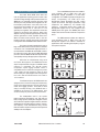
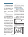
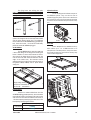
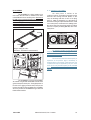
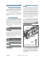
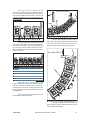
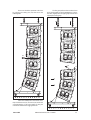
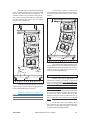
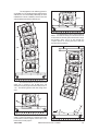
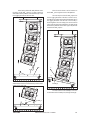
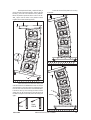
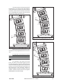
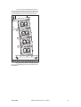
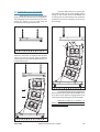
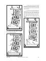
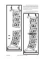
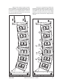
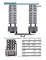
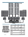
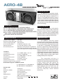
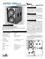
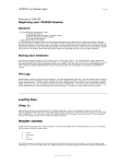
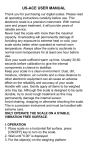
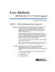
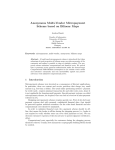
Aero -48
MANUAL DEL USUARIO / USER ’S GUIDE
Precauciones de Seguridad
Safety Precautions
El signo de exclamación dentro de un triángulo indica la existencia
de importantes instrucciones de operación y mantenimiento en la
documentación que acompaña al producto.
The exclamation point inside an equilateral triangle is intended to
alert the users to the presence of important operating and
maintenance (servicing) instructions in the literature accompanying
the product.
El doble cuadrado indica equipo de Clase 2.
The double square indicates Class 2 device.
No exponga este equipo a lluvia o humedad.
Do not expose this device to rain or moisture.
No emplace altavoces en proximidad a equipos sensibles a campos
magnéticos, tales como monitores de televisión o material
magnético de almacenamiento de datos.
Do not place loudspeakers in proximity to devices sensitive to
magnetic fields such as television monitors or data storage
magnetic material.
No existen partes ajustables por el usuario en el interior de este
equipo.
No user serviceable parts inside.
475
1400
WARNING! DO NOT SUSPEND FROM THIS HANDLE
¡ATENCIÓN! NO CUELGUE LA CAJA DE ESTE ASA
WARNING! DO NOT SUSPEND FROM THIS HANDLE
¡ATENCIÓN! NO CUELGUE LA CAJA DE ESTE ASA
AERO-48
1010
ALL DIMENSIONS IN MILIMETERS
WARNING! DO NOT SUSPEND FROM THIS HANDLE
¡ATENCIÓN! NO CUELGUE LA CAJA DE ESTE ASA
WARNING! DO NOT SUSPEND FROM THIS HANDLE
¡ATENCIÓN! NO CUELGUE LA CAJA DE ESTE ASA
36
224
680
236
823
256
36
220
The loudspeakers used in the system
feature advanced technologies; new TAF (total air
flow) cooling systems, Neodymium magnetic circuits
which allow for important weight reductions, titanium
diaphragms for the high frequency sections, and lowmid frequency cones manufactured using crossed
fibers and elastic suspension that provide exceptional
stability in the vertical plane.
WARNING! DO NOT SUSPEND FROM THIS HANDLE
¡ATENCIÓN! NO CUELGUE LA CAJA DE ESTE ASA
WARNING! DO NOT SUSPEND FROM THIS HANDLE
¡ATENCIÓN! NO CUELGUE LA CAJA DE ESTE ASA
To facilitate transport, the AERO-48 units are
equipped with a PL-48 front dolly panel attached by
means of the rigging hardware. The front dolly panel is
useful when rigging systems. The PL-48S, a metal
dolly for vertically stacking 3 to 4 AERO-48 units is
available as an accessory. The AERO-218SUB units
can be moved by way of the four rear located casters.
WARNING! DO NOT SUSPEND FROM THIS HANDLE
¡ATENCIÓN! NO CUELGUE LA CAJA DE ESTE ASA
595
Both units are manufactured using 15/18
mm Finnish Birch plywood. The AERO-48 enclosure
shape is trapezoidal with 5º angles. The AERO-218SUB
enclosure is rectangular. The Aero-48 system
incorporates captive rigging hardware which is
compatible with one another and designed to provide
a fast, simple and safe rigging by means of quick
release safety pins. Splay angles can be changed from
0º to 3.2º in 0.8º increments and from 3.2º to 9.6º in
1.6º increments.
WARNING! DO NOT SUSPEND FROM THIS HANDLE
¡ATENCIÓN! NO CUELGUE LA CAJA DE ESTE ASA
The system is ideal for applications such as
large-scale outdoor/indoor events in arenas, stadiums
or theaters. Use of the DSP-3VS digital processor is
recommended for the AERO-48 and the DSP-1Sub for
the subwoofer system. Not using the DSP-3VS digital
processor with the AERO-48 will adversely affect the
sound quality and may damage system components.
The AERO-218SUB includes two 18GN 18”
cone transducers with 4” EFW voice coils and
Neodymium magnets. This cabinet is intended for
applications when extending the frequency range of
the system is required.
WARNING! DO NOT SUSPEND FROM THIS HANDLE
¡ATENCIÓN! NO CUELGUE LA CAJA DE ESTE ASA
The D.A.S. Audio AERO series offers two
units for applications requiring precise control of the
vertical coverage and high sound pressure levels. The
AERO-48 is an externally powered, three-way, high
efficiency line array module which integrates two 15”
low frequency units with 4” voice coils, four 8” midrange devices which utilize 2.5” voice coils and two
compression drivers with 3” coils and 1.5” exit
geometry in a single unit. The compression drivers are
coupled to two Serpis high frequency plane wave
adaptors insuring coherent high frequency summing
and the generation of a flat, isophasic wave front.
When increased sound pressure level in the low
frequency range is required, the system can be used
in conjunction with the AERO-218SUB subwoofer unit.
The model AERO-48 includes two 15GN 15”
cone transducer with 4” EFW voice coils and
Neodymium magnet assemblies in a bass-reflex
configuration. Four 8MN, 8” speakers arranged on a V
shape, incorporating 2.5” EFW voice coils,
Neodymium magnet assemblies and TAF cooling
system are used for mid-range reproduction. High
frequencies are handled by two M-10N high
frequency compression drivers with 3” EFW coil,
Neodymium magnet and 1.5” exit coupled to twin
SERPIS plane wave guide. The SERPIS plane wave
adaptor also serves as a heat sink for the compression
driver.
WARNING! DO NOT SUSPEND FROM THIS HANDLE
¡ATENCIÓN! NO CUELGUE LA CAJA DE ESTE ASA
1. SYSTEM DESCRIPTION
AERO-218SUB
ALL DIMENSIONS IN MILIMETERS
Aero-48
Manual del usuario/ User´s manual
30
2. RIGGING SYSTEM
2.1WARNING
This manual contains needed information for
flying DAS Audio line array systems, description of
the elements and safety precautions. To perform any
operations related to flying the system, read the
present document first, and act on the warnings and
advice given. The goal is to the allow the user to
become familiar with the mechanical elements
required to fly the acoustic system, as well as the
safety measures to be taken during set-up and
teardown.
Only experienced installers with adequate
knowledge of the equipment and local safety
regulations should fly speaker boxes. It is the user's
responsibility to ensure that the systems to be flown
(including flying accessories) comply with state and
local regulations.
The working load limits in this manual are
the results of tests by independent laboratories. It is
the user's responsibility to stay within safe limits. It is
the user's responsibility to follow and comply with
safety factors, resistance values, periodical
supervisions and warnings given in this manual.
Product improvement by means of research and
development is ongoing at D.A.S. Specifications are
subject to change without notice.
Absolutely no risks should be taken with
regards to public safety. When flying enclosures from
ceiling support structures, extreme care should be
taken to assure the load bearing capabilities of the
structures so that the installation is absolutely safe.
Do not fly enclosures from unsafe structures. Consult
a certified professional if needed. All flying
accessories that are not supplied by DAS Audio are
the user's responsibility. Use at your own risk.
2.2 DESCRIPTION/ACCESSORIES
DAS Audio AERO-48 line array systems,
include 2 rigging structures on each side of the box.
Manufactured from zinc plated steel they are painted
black and are affixed to an internal plate with special
crop resistant screws. Two special stainless steel
guides are assembled to each of the structures:
G1A48 (front guide) and G2A48 (back guide), allow for
stacking or flying of boxes. Splay angles can be
changed from 0º to 3.2º in 0.8º increments and from
3.2º to 9.6º in 1.6º increments. To lock both guides,
six (6) quick release safety pins (supplied) must be
used.
The G1A48 front guide provides a solid
connection to the box and whatever is on top of it,
while the G2A48 rear guide determines the vertical
splay angle (whether stacked or flown), as a function
of the hole where the pin gets inserted.
G2A48
To this date, there is no international
standard regarding the flying of acoustic systems.
However, it is common practice to apply 5:1 safety
factors for enclosures and static elements. For slings
and elements exposed to material fatigue due to
friction and load variation the following ratios must be
met; 5:1 for steel cable slings, 4:1 for steel chain
slings and 7:1 polyester slings. Thus, an element with
a breaking load limit of 1000 kg may be statically
loaded with 200 kg (5:1 safety factor) and
dynamically loaded with 142 Kg (7:1 safety factor).
When flying a system, the working load
must be lower than the resistance of each individual
flying point in the enclosure, as well as each box.
Hanging hardware should be regularly inspected and
suspect units replaced if in doubt. This is important to
avoid injury and absolutely no risks should be taken in
this respect. It is highly recommended that you
implement an inspection and maintenance program
on flying elements, including reports to be filled out by
the personnel that will carry out the inspections. Local
regulations may exist that, in case of accident, may
require you to present evidence of inspection reports
and corrective actions after defects were found.
QUICK RELEASE PIN 8X30
(6 UNITS PER CABINET)
G1A48
To aid the setting of the G2A48 guide in the
corresponding hole in the top box, each hole is labeled
with an associated angle, both for stacked and flown
applications. To fit the guides into the holes, highly
resistant 8 mm quick release pins with a ball safety
lock are used.
Fly
9.6º 8º
8º 6.4º
6.4º 4.8º
®
SOUND PRODUCTS
WARNING! DO NOT SUSPEND FROM THIS HANDLE
¡ATENCIÓN! NO CUELGUE LA CAJA DE ESTE ASA
®
SOUND PRODUCTS
WARNING! DO NOT SUSPEND FROM THIS HANDLE
¡ATENCIÓN! NO CUELGUE LA CAJA DE ESTE ASA
4.8º 3.2º
3.2º 1.6º
2.4º 0.8º
1.6º 0º
0.8º
0º
Aero-48
9.6º
Manual del usuario/ User´s manual
Stack
31
For flying boxes and defining the splay
angle, the pins must be inserted in the slot of guide 2,
G2A48, whereas for stacking (stacked), the pin goes
through the top hole of the guide.
C) Platform PL-48
The PL-48 dolly panels facilitate transport of
the AERO-48 systems. They can also be used to
facilitate flying the systems. Each cover is attached to
the enclosure by using the flying hardware attached
to each box and is fixed with the quick release safety
pins.
FLY
STACK
All of the elements needed to rig or stack the
systems are integral to the enclosure (G1A48, G2A48
and the quick release safety pins). The additional
items needed are the AX-AERO48 flying grid (bumper
bar), chains and hoists, the PL-48 or PL-48S dolly
platforms and the AX-COMBO flying grid.
A) AX-AERO48
The AX-AERO48 grid is made from 100 x 50
x 6mm steel tubing and is designed to handle great
loads. It features a center reinforcement bar that is
also used for the lifting slings. The force of both the
rear and the front chain hoist will determine the tilt
angle of the whole array. The structure will be
attached to the first enclosure of the array by means of
the guides G1A48, G2A48, and six quick release
safety pins.
Pickup points
PL-48
D) PL-48S
The PL-48S platform is a valuable accessory
which allows up to 3 or 4 AERO-48 units to be
transported in a stacked position, ready to be flown.
The PL-48S is made from steel and has 4 heavy duty
casters with locking brakes.
PL-48S
Weight: 75Kg (165 lbs)
Dimensions: 144x93x10 cm
(H x W x D) 57x36.6x4 in
B) Chain hoists
All units in a column will be flown from the
AX-AERO48 flying grid (bumper bar), which should be
used with two hoists, one located in the front and the
other in the rear. The hoists should have a minimum of
1 Ton load capacity when flying up 8 units and a 2 Ton
load capacity when flying 9 to 16 units.
Chain hoist load capacity
1-->8cabinets
9-->16cabinets
Aero-48
>1000Kg
>2000Kg
Manual del usuario/ User´s manual
32
2.3 SAFETY FACTORS
D) AX-COMBO
The AX-COMBO is a rigging adapter to be
used when Aero-28 units are needed to be flown
under AERO-48 units as dowfill systems. Maximum 6
CA-28A units and 8 CA-28/CA-28B units can be flown
from this rigging grid. The AX-COMBO includes front
and rear steel guides which permit variation of the
angle between it and the last AERO-48 cabinet in the
cluster. Angles vary from 1.8º to 9.6º.
G1A48
The safety factor is defined as the
coefficient between the breaking load limit and the
maximum safe working load limit (SWLL). In this
case, the breaking load limit of each of the flying
points is 4,000 kg (8,820 lbs) as determined by
destructive testing in independent laboratories. With
a 10:1 safety factor, a total amount of 1,600 kg (3,527
lbs) can be flown from the 4 flying points. Each flying
point has a capacity of 400 kg (882 lbs) with a 10:1
safety factor.
G2A48
4 x 400Kg (10:1)
G2A48
Weight: 16.5Kg (36.3 lbs)
Dimensions: 143x60x5cm (56.3x23.6x2in)
The maximum number of units that can be
suspended from the AX-AERO48 flying grid is 16. The
maximum limits established by the manufacturer
should never be exceeded.
AERO-48
The use of two hoists with a load capacity as
expressed on the previous page is mandatory. It
should be kept in mind that at certain moments, the
complete load may be supported by only one of the
hoists. This is why the load capacity of the individual
hoist must be superior to the weight of the array
column.
G2A48
AX-COMBO
CA-28
G1A48
The AX-COMBO is joined to the last AERO48 cabinet using G1A48 and G2A48 included steel
guides and 6 quick release pins. The angle depends on
the hole of the rigging structures where the pins are
inserted, through the slots of G2A48. The first AERO28 unit is joined to the AX-COMBO using its G1A and
G2A included cam links.
Aero-48
Manual del usuario/ User´s manual
33
3. ASSEMBLING AN ARRAY
3.1TRANSPORTING THE CABINETS
AERO-48 units can be transported by using
the front panel dolly PL-48 or by using the PL-48S steel
dolly which can transport a maximum of 3 AERO-48
stacked in an arc or 4 units stacked vertically.
The Aero-218SUB can be transported on the
rear located casters. Their rectangular shape
facilitates stacking without the use of the rigging
hardware.
3.2 PLANNING/INSPECTION
Before installing the AERO systems it is a
good idea to run a simulation with the AEROWARE
program utilizing the venue dimensions. This way we
can determine the needs that should be met by the
rigging structures such as hoists, cranes, beams,
rigging points, etc. Besides providing weight
information, the program also provides users with
splay angle information, safety pin positions and
coverage predictions.
It is extremely important to assure that each
and every one of the aforementioned structures is
capable of supporting a superior load than that of the
complete system.
3.3 ASSEMBLING AN ARRAY “ONE
BY ONE”
When few units are to be used (minimum
systems recommended is 6 units) or when the dolly
platforms cannot be used due to a lack of space, the
enclosures will have to be hung “one by one”. The first
step will to attach the AX-AERO48 grid structure to
the hoists. The chain slings need to be attached to the
structure using the shackles provided with the grid.
Once this has been accomplished, the grid structure
can be placed in a vertical position by lifting the rear
hoist and lowering the front hoist so that the rear of
the grid is on top and the front of the grid at the
bottom, ready to receive the first box.
The next step is to attach the first unit to the
grid by introducing the G1A48 and G2A48 guides in
the receiving points of the grid structure and assuring
them with the six safety pins. The safety pins should
be inserted in the slot of the G2A48. It is very
important to make sure that the pins have been
inserted and locked correctly.
AERO-48
G2A48
3
Inspection is the next step after planning
and acquiring all the necessary parts needed to
elevate the systems. All parts, including the hardware
attached to the enclosure, the safety pins, etc. should
be thoroughly inspected before each use. Units
exhibiting deformations, cracks or any other defect
should be replaced with new units.
It is important to establish an inspection
routine for the complete rigging system before each
event or installation as well as establishing the
maximum load specifications of the hoists to be used.
1
AX-AERO48
5
6
G1A48
Rigging should be carried out by experts
familiar with the way the systems function and their
characteristics.
On occasions, it may be convenient to have
additional tie down points to impede the array from
twisting or swinging.
2
4
3+4
The quick release pins(3 and 4) must be
inserted through the slot of G2A48
Once the first unit of the array has been
attached to the AX-AERO48, the assembly should be
lifted by way of the rear hoist until the wheels of the
PL-48 dolly platform lift off the ground. From this point
on, the front hoist can be used to lift the box into a
horizontal position.
Aero-48
Manual del usuario/ User´s manual
34
Lifted by way of the rear hoist
until the wheels of the PL-48
dolly platform are off the ground.
Swing the G2A48 guide
into place and secure it
with the safety pin.
Lift with the front hoist
until the box is in a
horizontal position.
Once the splay angle between the first two
boxes has been determined, the front of the box can
be lifted into place. Three people will be needed to
undertake this operation, two to lift the box and one to
fit the G1A48 guide and safety pins into the upper box.
0º
Once the first box has been placed at 0º and
raised approximately 75cm (30 in) the second box of
the array can be placed nearby. Once located in
position, the G2A48 guides of the second box should
be freed and inserted in the rear located receiving
points of the suspended box and secured with the
safety pins.
Lift the box and free
the G1A48 guides.
Aero-48
Manual del usuario/ User´s manual
35
3.4 ASSEMBLING AN ARRAY USING
THE PL-48 PLATFORM
The PL-48 platform can be used to easily
transport AERO-48 units to the assembling area. To
use this method of assembling and hoisting the array,
there must be enough space to permit linking all the
boxes from the front of the the rigging hardware.
The first step will be to attach the AXAERO48 grid and the 2 hoists. Once this has been
accomplished, the grid structure can be placed in a
vertical position by lifting the rear hoist and lowering
the front hoist so that the rear of the grid is on top and
the front of the grid at the bottom, ready to receive the
first box.
Rigging points
Lift the box and introduce the
G1A48 guides securing them
with the safety pins.
Once the boxes have been joined, the front
dolly panels can be removed. The next boxes should
be attached “one by one” using the methods
described. Finally, the array should be hoisted to the
correct height and secured with slings to avoid
swinging.
This method is more time consuming than
assembling an array by the “all at once” procedure,
but is appropriate for situations due to a lack of space
in which to array the system. During the process, the
safety pins should be checked making sure they are
secured correctly. Once the complete array has been
lifted into place, additional slings should be attached
to secure the array and avoid swinging.
The next step is to attach the first unit to the
grid by introducing the G1A48 and G2A48 guides in
the receiving points of the grid structure and assuring
them with the (6) safety pins. The safety pins should
be inserted in the slot of the G2A48. It is very
important to make sure that the pins have been
inserted and locked correctly.
AERO-48
G2A48
3
4
2
1
AX-AERO48
5
6
G1A48
3+4
Aero-48
Manual del usuario/ User´s manual
36
Once the first box is attached to the
structure, the remaining boxes should be brought to
the array and attached repeating the previous steps (1
and 2) using G1A48 guides and safety pins per side
making sure that the pins have been inserted and
locked correctly.
Rear hoist FIRST!!
3
5
G2A48
4
4
1
G1A48
2
Proceed to attach the remaining units in the
same manner until all the array units are attached to
one another. For example, if we are assembling a six
unit array, the process will be repeated six times.
When all the units are attached, the complete array is
ready to be hoisted.
The complete assembly should begin being
lifted from the rear hoist (3) so that the rear of the
enclosures come together due to their trapezoidal
shape. The front motor will be used only to take up
slack in the chain, all the weight should be on the rear
hoist. Proceed in this manner until the wheels of the
last enclosure are off the ground. From here on, the
array can now be lifted with both motors.
The front motor will be used only to take up
slack in the chain, all the weight should be on the rear
hoist. When the wheels of the last enclosure are off
the ground the array can be lifted with both motors.
Rear hoist FIRST!!
6
When the rear of the enclosures come
together, the G2A48 rear guides should be positioned
(4) into the hardware of the box above, inserting (5)
the safety pins in the correct angle position. Since the
boxes are flown, the safety pins should be in the slot of
the G2A48 guide.
7
As the array assembly is lifted (6 & 7), the
PL-48 platforms should be removed.
Once the complete array has been lifted into
place, additional slings should be attached to secure
the array and avoid swinging.
Aero-48
Manual del usuario/ User´s manual
37
Aero-48
Manual del usuario/ User´s manual
38
To lower the system, both hoists should be
used until the lowest box is about 1 meter from the
ground. From there on, only the front hoist should be
used so that the array assembly begins to lean
forward, at the same time, the PL-48 platforms should
be reattached. When the wheels of the lowest
enclosure are firmly on the ground, the array
assembly can now be lowered using the rear hoist.
While the array assembly descends, the
rear of the enclosures will come together, at that
moment, the safety pins which hold the G2A48
guides in place should be removed. Once removed,
the guides should be swung back into the box they
belong to. Finally, the boxes should be totally
detached from one another by releasing the G1A48
guide.
The PL-48S platform can be used to
transport boxes forming a vertical arc, ready to be
flown or simply stacked.
Either way, due to the weight of the boxes, it
is recommended that for the first time, the enclosures
be placed on the platform from a flown position. In
other words, the array should be suspended (either
one by one or using the PL-48S) and then lowered onto
the PL-48S in groups.
A) Cabinets splayed in arc (MAX. 3 units):
If we want to place six AERO-48 units on 2
PL-48S, the first step would be to suspend them all,
and then lower the array assembly onto the platforms
in groups of three.
Last cabinet of the array
3.5 ASSEMBLING AN ARRAY
USING THE PLATFORM PL-48S
The PL-48S platform can be used to easily
transport 3/4 units of the AERO-48; in both arc shape
or stacked on the platform.
MAX. 3
units
MAX. 4
units
Lower the array until the lowest box is about
15 cm (aprox. 6 in.) above the PL-48S platform.
Splayed units on PL48S ready to be rigged.
Units stacked on a PL48S.
The PL-48S platform has two types of
moving pieces. One of them is fixed (PL-48S_2) and
can only be swung around, the other is free (PL48S_1) and is joined to the platform by way of a safety
pin. The smaller piece PL-48S_1 attaches to the front
enclosure hardware and the larger PL-48S_1 attaches
to the back:
PL-48S_1
2
1
Release the PL-48S_2 piece by removing
the safety pins (1). Next, swing the pieces and
introduce them (2) into the rear rigging hardware of
the lowest box, securing them with the safety pin (3).
PL-48S_2
Aero-48
Manual del usuario/ User´s manual
39
Once the two PL-48S_2 have been attached
to the boxes (3) using one safety pin per piece, the PL48S_1 pieces can be attached. Remove the safety
pins (4)and insert them into the rigging hardware (5)
securing them (6) by using two pins per piece.
1
3
2
5
6
4
Once the PL-48S_1 and PL-48S_2 have
been secured to the lower box, this should be lowered
so that the PL-48S_1 piece can be secured to the PL48S platform (7) using the safety pins.
3
8
9
4
9
8
7
The lowest box is now attached to the
platform. Now the array should be lowered until the
boxes are resting on one another. When the lower
three boxes are in this position, the safety pins
attached to the G2A48 guides joining boxes 3 and 4
should be removed to separate the array into two
groups of boxes.
5
9
8
6
On flown systems, boxes are numbered
from top to bottom, the top box being number 1 and
the lower box being number six.
With the number 4, 5 & 6 boxes resting on
each other, the safety pins that define the splay angle
can be removed (8) and the PL-48S_2 guides can
return to their stored position (9). It is mandatory to
remove the safety pins between boxes 3-4, but
between 4-5, and 5-6, they can be left in place with
the angle prepared for the next event.
Aero-48
Manual del usuario/ User´s manual
40
Boxes 3-4 should be separated at the front
by removing the safety pins (10) that secure the
G1A48 guides.
The first group of boxes has now been freed
and is stacked safely on the PL-48S platform. To move
the stack, slightly raise the upper group of boxes and
roll away the lower group.
10
12
11
When the G1A48 pieces have been freed,
they should be turned (11) and stored (12) within the
corresponding box, in this case number 4, using the
mechanism included in the rigging hardware.
Aero-48
Manual del usuario/ User´s manual
41
The next step is to roll under the remaining
boxes, an empty PL-48S and lower the boxes until
they are within close proximity of the platform. The
procedure should now be repeated, freeing the PL48S_2 pieces (13) from the platform, turning them
(14) and securing them (15) to the rear rigging
hardware of the number 3 box.
The last step consists of lowering the
remaining array so that the safety pins can be inserted
(18) into the holes of the PL-48S_1 pieces and the
platform.
18
15
17
PL-48S_2
16
PL-48S_1
As in the case of the first group of boxes, it is
not necessary to remove the safety pins securing the
G2A48 guides which determine splay angle. They can
remain in as they are, ready for the next event. The
same goes for the AX-AERO48 grid.
14
B) Stacked units (MAX. 4 units):
13
Continue lowering the systems and secure
(16) the PL-48S_1 pieces to the front rigging points of
box 3, inserting 2 safety pins in each (17).
Whenever a safety pin is inserted, it is
recommended that they be checked to make sure that
they are correctly attached. Pull the safety pin
outward to make sure that it is in the locked position.
Besides using the PL-48S platform for
transporting and flying the systems, it can also be
used for ground stacking. Due to the weight of the
boxes, it is recommended that they be flown first and
then lowered to the platform and stacked. For
stability reasons, it is recommended that no more
than 4 boxes be stacked. In the event that 4 boxes are
used, they should be arranged so that the splay angles
do not make the platform unstable. Once the boxes
are flown, they can be lowered onto the PL-48S
platform by using the hoists to position the array so
that the safety pins can be inserted into the G2A48
guides.
The PL-48S_2 piece on the platform has 2
holes, the lower one offers a 0º angle between box
and platform and the upper hole offers a 1.6º angle,
meaning that the box is leaning forward.
Aero-48
Manual del usuario/ User´s manual
42
The arrangement in the following picture is
an unstable one. The smaller the splay angle between
cabinets, the more the stability. Obviously, the most
reliable stack in terms of stability is the one when the
splay angle between all of the cabinets is 0º.
-1.6º
The angle between the box and the platform
will be -1.6º when the safety pin is inserted in the hole
on the bottom of the back guide, and the hole on top of
the PL-48S_2 piece. Let us go now through the
complete process of stacking the boxes after they
have been previously flown.
6.4º
4.8º
3.2º
As mentioned above, the hole in which the
safety pin is inserted in the PL-48S piece will
determine the splay angle of the bottom box, be it 0º or
-1.6º. The following pictures will make things more
clear.
0º
1
2
The angle between the box and the platform
will be 0º when the safety pin is inserted in the hole
on the bottom of the back guide, and the hole on the
bottom of the PL-48S_2 piece.
Aero-48
Manual del usuario/ User´s manual
43
After having rolled a PL-48S platform under
the array, the PL-48S_1 pieces (1,2 and 3) must be
detached from the platform and introduced (4) in the
front rigging structure of the lower box.
4
3
Now the entire cluster can be lowered so
the PL-48S_1 pieces get into reach of the platform.
The next step is to fix the PL-48S_2 pieces to
the rear rigging hardware of the box. In order to do so,
the platform should be raised up till the bottom hole in
the rigging hardware and the hole in the PL-48S_2
match together. Then the safety pins can be inserted
in the holes. As has been said before, the splay angle
between the platform and the box is given by the hole
used in the PL-48S_2 piece.
7
6
Both PL-48S_1 pieces must now be
attached (5) to the box on the bottom by means of two
safety pins on each side.
PL-48S_2
The hole chosen in this example, is the one
on the bottom of the PL-48S piece, being 0º the angle.
5
Aero-48
PL-48S_1
Manual del usuario/ User´s manual
44
At this point the PL-48S_1 and the PL-48S_2
pieces are both connected to the box. There is only the
PL-48S_1 piece left to be attached to the platform.
Move the platform upwards till the holes in the PL48S_1 piece and the holes in the platform match
together. Then insert the safety pins (8).
Lower the cluster till the platform is resting
on the floor.
9
1
10
8
2
When the boxes are flown the safety pins
must be inserted in the G2A48 slots. Now we want to
stack the boxes, so the next step is to release the pins
from the slots and introduce them in the G2A48 holes.
It must be done by first lowering the boxes till the
safety pins can be removed, then raise the boxes till
the holes fit together and finally insert the safety pins
again.
11
3
G2A48
12
4
Fly
G2A48
Aero-48
Stack
G2A48
Manual del usuario/ User´s manual
45
The cluster must now be lowered (10) until
the safety pins (11) on the rear side of box number 4
can be removed. Once safety pins have been released
the cluster must be raised or lowered (13) until the
hole in the G2A48 piece matches with the hole that
determines the angle chosen by the user.
15
13
16
17
4.8º
14
19
Safety pins can now be inserted (14). In this
example, the set up angle between boxes 3 and 4 is
4.8º.
20
It is important to check that pins cannot be
removed by pulling outward and that they have been
inserted in the G2A48 hole instead of the guide slot.
Otherwise the box would not remain in the expected
angle.
18
The procedure is the same for the next
boxes. The cluster must be lowered again (15) until
the safety pins of box 3 are loose. Remove the pins
(16) so the G2A48 rear guides return to their stored
position (17). Insert the safety pins into the holes (18)
that determine the angle previously selected for
stacking. Repeat the same procedure with box
number 1: lower the cluster (19), free the rear guides
G2A48 (20 & 21) and select the angle.
Aero-48
21
3.2º
4.8º
Manual del usuario/ User´s manual
46
In order to set up the angle between boxes 1
and 2 you must pull up (23) from the grid until the hole
in the G2A48 piece fits with the hole that determines
the stacking angle. Then insert the safety pins (24).
23
24
1.6º
3.2º
4.8º
At this point the boxes are safely stacked.
Finally, the AX-AERO48 grid should be detached from
box number 1.
Aero-48
Manual del usuario/ User´s manual
47
3.6 ASSEMBLING A CLUSTER
USING THE PL-48S PLATFORM
AERO-48 boxes can be easily transported in
groups of three when stacked on the PL-48S platform.
This arrangement is also useful and saves time when
setting up a cluster. Let us see what would the
procedure be when flying a six box cluster.
In order to attach the box on top to the grid,
front guides G1A48 and rear guides G2A48 must be
swung (2) and inserted into the AX-AERO48 grid
receiving points. Once this has been done, detach the
6 safety pins from their receptacles and secure the
box to the grid.
1
1
2
2
After the AX-AERO48 grid has been
attached to the motors, it should be lifted at about
1.8m (5.5 ft) from the ground. Now the platform
containing the first three stacked AERO-48 boxes can
be rolled under the grid.
Once G1A48, G2A48 of the top cabinet have
been secured (3) to the grid, rotate the G2A48 pieces
(4), fit them into the upper box rigging hardware and
secure them with the safety pins (5). See next page.
Whenever a safety pin is inserted, it is
always advisable to make sure it has been correctly
locked by pulling outward.
Aero-48
Manual del usuario/ User´s manual
48
The angles that can be seen in the example
are 0.8º between the first and second boxes, and 1.6º
between the second and the third boxes. The cluster
can now be lifted by the two motors, and the PL-48S
platform detached.
3
3
The first step to detach the PL-48S platform
from the bottom box is to release (6) the safety pins
which secure the PL-48S_1 piece to the platform and
the PL-48S_2 piece to the box. After raising the
cluster a bit, the safety pins which connect the PL48S_1 piece to the box can be released (8) also. PL48S_1 piece should now be reattached again to the
platform.
4
4
Select the angle between cabinets
introducing (5) the pins in the holes of the rigging
system through the slot of G2A48.
0.8º
6
PL-48S_2
5
8
PL-48S_1
7
6
1.6º
5
Aero-48
Manual del usuario/ User´s manual
49
Place the remaining group of boxes under
the cluster, then lower the cluster until both front sides
get in close proximity. G1A48 front guides (9) of the
first box on the platform can now be swung and left in
the upright position, ready to be inserted into the front
rigging hardware of the next box.
Lower the cluster until the G1A48 front
guides fit into the rigging hardware of the bottom box
and insert the two safety pins (10)per side.
9
10
Aero-48
Manual del usuario/ User´s manual
50
With the front guides correctly secured,
swing the G2A48 (11) rear guides belonging to the
box on top of the second group and lower the grid till
the guides fit into the rigging hardware of the next
box. Set the angle between both boxes by inserting
the safety pins in the correct hole.
From here on, the process is similar to the
previously described. Detach the safety pins from
their receptacles on the sides of the boxes, swing (12)
the G2A48 rear guides, place them into the rigging
hardware of the next box and insert (13) the safety
pins in the holes which define the angle previously
selected.
0.8º
1.6º
1.6º
13
12
11
3.2º
13
12
4.8º
13
12
Aero-48
Manual del usuario/ User´s manual
51
4.2 LIMITER SETTINGS
4. SIGNAL PROCESSING
The use of the DSP-3VS digital processor is
highly recommended when running the AERO-48
sound system, and the use of the DSP-1Sub when
running the AERO-218Sub. Whenever another
loudspeaker management system is going to be used,
it should be configured with the parameters provided
by the manufacturer. Not doing so may damage the
system´s speaker components and affect the sound
quality.
The following formulas can be used to establish the
limiter voltage:
Amplifier Data:
Vrms= Prms * Z
G=Vrms/S
GdB=20log(Vrms/S)
Where Prms is the amplifier RMS power in
The DSP-3VS digital processor is a threeway crossover with gain controls that offer +/- 6dB
variation per way. The processor has two inputs and
six outputs with level indication and muting for each
of the outputs. The digital processor includes fourth
order filters and parametric equalizers. The user
adjustable limiters are accessible from the front panel.
watts
The DSP-3VS includes 10 presets that can
be selected from the front panel. Each preset memory
recalls specific operating parameters for a specific
DAS speaker systems. The selected program is visible
on the LCD screen located on the front panel.
Vd= Pd * Z
Limit level (v)=Vd/G
Limit level (dBu)=20log[limit level (v)/0.775]
4.1 DSP-3VS INSTRUCTIONS
Z is the load impedance in ohms
G is the amplifier gain
S is the amplifier sensitivity in volts
GdB is the amplifier gain in dB
Limiter settings:
Where Pd is the maximum power to be
delivered in watts
Ejemplo:
To select a program, turn the rotary mini-DIP
switch on the front panel labelled “Presets”. The name
of the recalled preset will appear on the LCD screen.
The first time the DSP-3VS is connected, the number 1
program for the AERO-48 system will appear on the
front panel screen.
To select the limit levels for each of the
ways, turn the rotary mini-DIP switches on the front
panel labelled “Limiters”. The limit level expressed in
Vrms and dBu appears on the front panel screen.
The “Settings” button allows the user to
check the saved limit levels. The limit levels appear on
the screen and after 5 seconds, the preset program
returns to the screen.
The limit levels to be entered should be equal
to or lower than the sensitivity of the amplifiers used.
Amplifier manuals provide the sensitivity at 8 Ohms
and 4 Ohms. Take into account the load impedance at
which the amplifiers will be working when adjusting
the limit levels.
When using amplifiers with a greater output
power than that recommended by the speaker
manufacturer, the limit levels should be adjusted so
not to exceed the power capabilities of the speakers.
Aero-48
Amplifier
Prms
1400W@4ohm
850W@8ohm
GdB
32dB
G
40 X
S
1.84 volts@4ohm
2 volts@8ohm
In this example we are going to feed the
highs of an AERO-48 with one amplifier channel. Total
impedance of 4 M-10N high frequency drivers, as
wired in the AERO48, is 8 Ohms. The maximum rms
power to be delivered to the highs, or Pd, should be
700W (700/4=175W per driver).
Pd=700W@8ohm
Vd= 700*8=74.8v
Limit level (v)=Vd/G=74.8/40=1.84
Limit level (dBu)=20log(1.84/0.775)=7.6
Important Notice: The programs stored in
the memories of the DSP-3VS have been designed to
provide optimum performance and balance between
the different ways. In order to maintain this balance,
equal gain amplifiers should be used.
Manual del usuario/ User´s manual
52
5. SYSTEM CONNECTION
CONFIGURATION 1 (3 WAY STEREO SYSTEM FOR MID-LARGE SIZED VENUES)
aero-48
DSP-3VS
LINE IN
CONNECTIONS
LINK
LINK
DSP-3VS OPERATING PARAMETERS
RECOMMENDED AMPLIFIERS
CH-A
CH-B
±4HF
2 x 600W@8ohm ±4HF
±3MF
±3MF
2 x 1200W@4ohm
±2LF2
±2LF2
2 x 1200W@4ohm
±1LF1
±1LF1
2 x 1200W@4ohm
Aero-48
LOW
MID
HIGH
GAIN
DELAY
POLARITY
0 dB
0.4 ms
Normal
0 dB
0.4 ms
Normal
-7 dB
0 ms
Invert
LOW-CUT
HIGH-CUT
30 Hz LR-24
158 Hz LR-24
158 Hz LR-24
1 kHz LR-24
1 kHz LR-24
EQ.1 FREQ.
50 Hz
EQ.1 LEVEL
+6 dB
EQ.1 BW. 0.8 oct (Q=1.8)
353 Hz
-2 dB
0.3 oct (Q=4.8)
2.5 kHz
-3 dB
0.35 oct (Q=4.1)
EQ.2 FREQ.
EQ.2 LEVEL
EQ.2 BW.
450 Hz
-3dB
0.8 oct (Q=1.8)
10.1 kHz
+12 dB
1 oct (Q=1.4)
EQ.3 FREQ.
EQ.3 LEVEL
EQ.3 BW.
650 Hz
-2dB
0.3 oct (Q=4.8)
12.5 kHz
+7 dB
0.3 oct (Q=4.8)
Manual del usuario/ User´s manual
53
CONFIGURATION 2 (4 WAY STEREO SYSTEM FOR MID-LARGE SIZED VENUES)
aero-48
aero-218SUB
aero218SUB
®
®
ELECTRONICS
ELECTRONICS
DSP-3VS
CONNECTIONS
DSP-1Sub
LINE IN
DSP-3VS + DSP-1SUB OPERATING PARAMETERS
SUB
LOW
MID
HIGH
GAIN
DELAY
POLARITY
+3 dB
Variable
Normal
0 dB
0.4 ms
Normal
0 dB
0.4 ms
Normal
-7 dB
0 ms
Invert
LOW-CUT
HIGH-CUT
23 Hz LR-24
85 Hz LR-24
50 Hz LR-24
158 Hz LR-24
158 Hz LR-24
1 kHz LR-24
1 kHz LR-24
EQ.1 FREQ.
60 Hz
36 Hz
2.5 kHz
353 Hz
EQ.1 LEVEL
+3 dB
+10 dB
-3 dB
-2 dB
EQ.1 BW.
0.4 oct (Q=3.6) 0.8 oct (Q=1.8) 0.3 oct (Q=4.8) 0.35 oct (Q=4.1)
RECOMMENDED AMPLIFIERS
CH-A
CH-B
±1LF
±1LF
2 x 1400W@4ohm
Aero-48
EQ.2 FREQ.
EQ.2 LEVEL
EQ.2 BW.
450 Hz
-3dB
0.8 oct (Q=1.8)
EQ.3 FREQ.
EQ.3 LEVEL
EQ.3 BW.
12.5 kHz
650 Hz
+7 dB
-2dB
0.3 oct (Q=4.8) 0.3 oct (Q=4.8)
Manual del usuario/ User´s manual
10.1 kHz
+12 dB
1 oct (Q=1.4)
54
6.OPERATING PARAMETERS
AERO-48 BSS OPERATING PARAMETERS
AERO-48+AERO218SUB BSS OPERATING PARAMETERS
SUB
LOW
MID
-7 dB GAIN
0 ms DELAY
Invert POLARITY
+3 dB
Variable
Normal
0 dB
0.4 ms
Normal
0 dB
0.4 ms
Normal
-7 dB
0 ms
Invert
1 kHz LR-24 LOW-CUT
HIGH-CUT
23 Hz LR-24
85 Hz LR-24
50 Hz LR-24
158 Hz LR-24
158 Hz LR-24
1 kHz LR-24
1 kHz LR-24
LOW
MID
HIGH
GAIN
DELAY
POLARITY
0 dB
0.4 ms
Normal
0 dB
0.4 ms
Normal
LOW-CUT
HIGH-CUT
30 Hz LR-24
158 Hz LR-24
158 Hz LR-24
1 kHz LR-24
EQ.1 FREQ.
50 Hz
EQ.1 LEVEL
+6 dB
EQ.1 BW. 0.8 oct (Q=1.8)
353 Hz
-2 dB
0.3 oct (Q=4.8)
EQ.2 FREQ.
EQ.2 LEVEL
EQ.2 BW.
450 Hz
-3 dB
0.8 oct (Q=1.8)
10.1 kHz EQ.2 FREQ.
+12 dB EQ.2 LEVEL
1 oct (Q=1.4) EQ.2 BW.
EQ.3 FREQ.
EQ.3 LEVEL
EQ.3 BW.
650 Hz
-2 dB
0.3 oct (Q=4.8)
12.5 kHz EQ.3 FREQ.
+7 dB EQ.3 LEVEL
0.3 oct (Q=4.8) EQ.3 BW.
60 Hz
36 Hz
353 Hz
2.5 kHz
2.5 kHz EQ.1 FREQ.
+3 dB
+10 dB
-2 dB
-3 dB
-3 dB EQ.1 LEVEL
0.4 oct (Q=3.6) 0.8 oct (Q=1.8) 0.3 oct (Q=4.8) 0.35 oct (Q=4.1)
0.35 oct (Q=4.1) EQ.1 BW.
AERO-48 XTA OPERATING PARAMETERS
LOW
MID
GAIN
DELAY
POLARITY
0 dB
0.4 ms
Normal
0 dB
0.4 ms
Normal
LOW-CUT
HIGH-CUT
29.5 Hz LR-24
157 Hz LR-24
157 Hz LR-24
1000 Hz LR-24
450 Hz
-3 dB
0.8 oct (Q=1.8)
HIGH
650 Hz
12.5 kHz
-2 dB
+7 dB
0.3 oct (Q=4.8) 0.3 oct (Q=4.8)
SUB
LOW
MID
-8.8 dB GAIN
0 ms DELAY
Invert POLARITY
+3 dB
Variable
Normal
0 dB
0.4 ms
Normal
0 dB
0.4 ms
Normal
-8.8 dB
0 ms
Invert
1 kHz LR-24 LOW-CUT
22 kHz LR-24 HIGH-CUT
20.9 Hz LR-24
83.4 Hz LR-24
49.6 Hz LR-24 157 Hz LR-24
157 Hz LR-24 1000 Hz LR-24
1 kHz LR-24
22 kHz LR-24
354Hz
2.52 kHz EQ.1 FREQ.
-2 dB
-3 dB EQ.1 LEVEL
0.28 oct (Q=5.1) 0.32 oct. (Q=4.5) EQ.1 BW.
EQ.2 FREQ.
EQ.2 LEVEL
EQ.2 BW.
454 Hz
-3 dB
0.75 oct (Q=1.9)
10.3 kHz EQ.2 FREQ.
+13.8 dB EQ.2 LEVEL
0.6 oct (Q=2.4) EQ.2 BW.
EQ.3 FREQ.
EQ.3 LEVEL
EQ.3 BW.
655 Hz
-2 dB
0.27 oct (Q=5.3)
12.7 kHz EQ.3 FREQ.
+5.5 dB EQ.3 LEVEL
0.17 oct (Q=8.5) EQ.3 BW.
HIGH
2.52 kHz
354Hz
59 Hz
34.4 Hz
-3 dB
-2 dB
+2.5 dB
+10 dB
0.36 oct (Q=4) 0.79 oct (Q=1.8) 0.28 oct (Q=5.1) 0.32 oct. (Q=4.5)
454 Hz
-3 dB
0.75 oct (Q=1.9)
BSS Audio
FDS 336 Omnidrive
Manual del usuario/ User´s manual
10.3 kHz
+13.8 dB
0.6 oct (Q=2.4)
12.7 kHz
655 Hz
+5.5 dB
-2 dB
0.27 oct (Q=5.3) 0.17 oct (Q=8.5)
One of the most important parts of a multi-way sound reinforcement system is the digital controller. There
are a lot of fine products available; D.A.S. Audio has selected the following ones apart from the DSP-3VS, DSP-1Sub
D.A.S. controllers:
Aero-48
10.1 kHz
+12 dB
1 oct (Q=1.4)
AERO-48+AERO218SUB XTA OPERATING PARAMETERS
EQ.1 FREQ.
50.6 Hz
EQ.1 LEVEL
+5.5 dB
EQ.1 BW. 0.67 oct (Q=2.1)
Company
Model
HIGH
XTA Electronics
DP 226
55
7. POWERING THE SYSTEM
The following tables present power data delivered to each component and limiter settings depending on
the amplifier model:
D.A.S H-4000 AMPLIFIER GAIN 40x / 32 dB
AMPLIFIER CONFIGURATION: 4 x AERO-48 / 4 x H-4000
AMPLIFIER
CHANNEL
SPEAKON NL8
PINS
NUMBER OF
SPEAKERS
LOAD
IMPEDANCE
POWER AT
NOMINAL
IMPEDANCE
RECOMMENDED
LIMITATION
POWER
PER
SPEAKER
LIMITER
V /dBu
CH-1
Amplif. 4(HF)
CH-2
PINS ±4
4 x M-10N
8W
850 W
700 W / 8 W
175 W
1.84 / 7.6
PINS ±4
4 x M-10N
8W
850 W
700 W / 8 W
175 W
1.84 / 7.6
CH-1
Amplif. 3(MF)
CH-2
PINS ±3
8 x 8MN
4W
1400 W
1400 W / 4 W
175 W
1.84 / 7.6
PINS ±3
8 x 8MN
4W
1400 W
1400 W / 4 W
175 W
1.84 / 7.6
CH-1
Amplif. 2(LF)
CH-2
PINS ±2
2 x 15GN
4W
1400 W
1400 W / 4 W
700 W
1.84 / 7.6
PINS ±2
2 x 15GN
4W
1400 W
1400 W / 4 W
700 W
1.84 / 7.6
CH-1
Amplif.1(LF)
CH-2
PINS ±1
2 x 15GN
4W
1400 W
1400 W / 4 W
700 W
1.84 / 7.6
PINS ±1
2 x 15GN
4W
1400 W
1400 W / 4 W
700 W
1.84 / 7.6
D.A.S E-20 AMPLIFIER GAIN 40.6x / 31.5 dB
AMPLIFIER CONFIGURATION: 4 x AERO-48 / 4 x E-20
AMPLIFIER
CHANNEL
SPEAKON NL8
PINS
NUMBER OF
SPEAKERS
LOAD
IMPEDANCE
POWER AT
NOMINAL
IMPEDANCE
RECOMMENDED
LIMITATION
POWER
PER
SPEAKER
LIMITER
V /dBu
CH-1
Amplifier 4(HF)
CH-2
PINS ±4
4 x M-10N
8W
600 W
600 W / 8 W
150 W
1.84 / 7.6
PINS ±4
4 x M-10N
8W
600 W
600 W / 8 W
150 W
1.84 / 7.6
CH-1
Amplifier 3(MF)
CH-2
PINS ±3
8 x 8MN
4W
1000 W
1000 W / 4 W
125 W
1.65 / 6.6
PINS ±3
8 x 8MN
4W
1000 W
1000 W / 4 W
125 W
1.65 / 6.6
CH-1
Amplifier 2(LF)
CH-2
PINS ±2
2 x 15GN
4W
1000 W
1000 W / 4 W
500 W
1.65 / 6.6
PINS ±2
2 x 15GN
4W
1000 W
1000 W / 4 W
500 W
1.65 / 6.6
CH-1
Amplifier 1(LF)
CH-2
PINS ±1
2 x 15GN
4W
1000 W
1000 W / 4 W
500 W
1.65 / 6.6
PINS ±1
2 x 15GN
4W
1000 W
1000 W / 4 W
500 W
1.65 / 6.6
Aero-48
Manual del usuario/ User´s manual
56
AERO-48
series
INTRODUCTION
The AERO-48 is an externally powered,
high efficiency line array module which integrates
low, mid and high frequency transducers in a
single unit. The ruggedly built enclosure is easy to
transport by means of the front panel dolly and the
captive rigging hardware makes flying safe and
simple. The unit is ideal for applications requiring
high sound pressure levels and precise control of
the vertical coverage.
FEATURES
THREE-WAY, HIGH DIRECTIVITY LINE ARRAY MODULE
2 x 15” LOW FREQUENCY NEODYMIUM CONE TRANSDUCERS
4 x 8” MID FREQUENCY NEODYMIUM CONE TRANSDUCERS
2 x 1.5” EXIT, 3” DIAPHRAGM NEODYMIUM COMPRESSION DRIVER
TWIN “SERPIS” PLANE-WAVE GENERATORS
AERO-WARE PREDICTION SOFTWARE
45Hz-18kHz
90º nominal
Splay dependent
LF: 99dB MF: 104dB HF: 112dB
LF: 137dB MF: 139dB HF: 141dB
The AERO-48 three-way system
incorporates two15” low frequency units with 4”
voice coils, four 8”mid-range devices which utilize
2.5” voice coils and two compression drivers with
3” coils and 1.5” exit geometry. The compression
DAS digital controller DSP-3VS. Using AERO-48 drivers are coupled to two Serpis high frequency
system without the DSP-3VS controller will result plane wave adaptors which insure coherent high
in poor sound quality and can damage transducers frequency summing and the generation of a flat,
isophasic wavefront. The components make use
of lightweight neodymium magnet assemblies for
2 x 15”-MODEL 15GN, 4” voice coil
overall weight reduction and the sophisticated
2x8 ohms/ 2x 600W RMS
T.A.F. cooling scheme provides higher power
handling and low power compression.
4 x 8”-MODEL 8MN, 2.5” voice coil
Transducers
Low frequency
Nominal impedance/ power
Mid frequency
Nominal impedance/ power
8 ohms/ 700W RMS
High frequency
2 x M-10N, 3” voice coil
Nominal impedance/ power
16 ohms/ 300W RMS
Neodymium magnets in all the transducers
Recommended amp power 2xAERO-48 in parallel
LF1 1000/1400W 4W LF2 1100/1400W 4W
MF 1000/1400W 4W HF 600/800W 8W
Enclosure detail
Shape
Dimensions (HxWxD)
Material
Finish
Rigging hardware
Connector
Weight
The AERO-48 system is well suited for
large-scale outdoor events or indoor venues such
as theaters, arenas or stadiums. The system can
be used in conjunction with the AERO-218SUB
subwoofer unit for increased sound pressure level
in the low frequency range from 28 Hz to 83 Hz.
DESCRIPTION
SPECIFICATIONS
Frequency response ( 3dB)
Horizontal coverage angle (-6dB)
Vertical coverage angle (-6dB)
On axis sensitivity 1W/1m
Maximum peak SPL
Recommended processor
APPLICATIONS
The trapezoidal enclosure is
manufactured from Wisa® birch plywood and is
finished in a durable catalyzed polyurethane paint.
A fabric covered steel grill protects the
loudspeaker components. The captive rigging
hardware and 5º enclosure angles permit splay
angles ranging from 0º to 9.6º in 0.8º and 1.6º
increments. Ten handles and a front panel dolly
with four heavy-duty casters facilitate
maneuvering.
Trapezoidal 5º
47.5x140x60cm (18.7x55x23.6in)
Wisa Birch Plywood
Black polyurethane paint
Integrated in cabinet
MAX. 16 units@10:1 Safety factor
2x NL8 Speakon wired as LF1 1 LF2 2 MF 3 HF 4
100kg (220lbs)
®
SOUND PRODUCTS
AERO-218SUB
series
INTRODUCTION
The AERO-218SUB is a high efficiency,
arrayable subwoofer unit designed to provide low
frequency reinforcement for the AERO-48. The
front-loaded bass-reflex configuration and large
enclosure volume offer a compelling bass
response.
APPLICATIONS
The AERO-218SUB is designed for
applications where high sound pressure levels of
extended low frequency response are needed.
Events such as live concerts or large scale
presentations will benefit from the AERO-21SUB.
DESCRIPTION
The AERO-218SUB incorporates two 18”
low frequency units with 4” voice coils and
lightweight neodymium magnet assemblies. The
sophisticated T.A.F. cooling scheme offers
effective heat removal for high power handling and
low power compression. The rectangular
enclosure is manufactured from Wisa® birch
plywood and is finished in a durable catalyzed
polyurethane paint. A fabric covered steel grille
protects the loudspeaker components. The
rectangular shape and physical dimensions of the
AERO-218SUB allow the unit to be ground stacked
with ease. Eight handles and four heavy-duty
casters facilitate maneuvering.
FEATURES
DIRECT RADIATING SUBWOOFER UNIT
EXTENDED LOW FREQUENCY RESPONSE
2 X 18” LOW FREQUENCY NEODYMIUM CONE TRANSDUCERS
FOUR HEAVY-DUTY CASTERS
SPECIFICATIONS
28Hz-83Hz
103dB
140dB
DAS controller DSP-1Sub
1400W @4 ohm
Transducers
Low frequency
Nominal impedance
Neodymium magnets
2 x 18”-MODELO 18GN, 4” bobina
4 ohms wired in parallel
Enclosure
Shape
Dimensions (HxWxD)
Material
Finish
Connector
Weight
The AERO-218Sub unit has a frequency
range covering 28 Hz to 83 Hz (±3 dB) with a
sound pressure level reaching 140 dB SPL at 1
meter. The DSP-1Sub processor permits sub level
and phase adjustments.
1010
Frequency response ( 3dB)
On axis sensitivity 1W/1m
Maximum peak SPL
Recommended processor
Recommended amp power
WARNING! DO NOT SUSPEND FROM THIS HANDLE
¡ATENCIÓN! NO CUELGUE LA CAJA DE ESTE ASA
Rectangular
101 x 68 x 82.5cm (40 x 27 x 32.5in)
Wisa Birch Plywood
Black polyurethane paint
2x NL8 wired as ±1
82kg (181lbs)
WARNING! DO NOT SUSPEND FROM THIS HANDLE
¡ATENCIÓN! NO CUELGUE LA CAJA DE ESTE ASA
36
224
680
236
823
220
WARNING! DO NOT SUSPEND FROM THIS HANDLE
¡ATENCIÓN! NO CUELGUE LA CAJA DE ESTE ASA
WARNING! DO NOT SUSPEND FROM THIS HANDLE
¡ATENCIÓN! NO CUELGUE LA CAJA DE ESTE ASA
®
256
36
ALL DIMENSIONS IN MILIMETERS
SOUND PRODUCTS
US/AERO-01
D.A.S AUDIO, S.A. C/. Islas Baleares, 24 - 46988 Fuente del Jarro - Valencia, SPAIN Tel. 96 134 0525 - Tel. Intl. +34 96 134 0860 Fax. 96 134 0607 - Fax. Intl. +34 96 134 0607
D.A.S AUDIO of AMERICA, Inc. Sunset Palmetto Park- 6816 NW 77th Court - Miami, FL 33166 U.S.A. TOLL FREE : 1-888DAS4USA Tel. 305 436 0521 - Fax. 305 436 0528
http://www.dasaudio.com