1
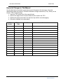
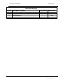
User Manual 07507200
Model 720x
Model 720x
Microwave Coaxial Switch
Page 1
Operation Manual
User Manual 07507200
Model 720x
All technical data and specifications in this publication are subject to change without prior notice and do not
represent a commitment on the part of Giga-tronics, Incorporated.
© 2011 Giga-tronics Incorporated. All rights reserved. Printed in the U.S.A.
Warranty
Giga-tronics Series 7000 Switching Modules are warranted against
defective materials and workmanship for three years from date of shipment,
or as detailed in the warranty section of this manual. Giga-tronics will, at its
option, repair or replace products that are proven defective during the
warranty period. This warranty DOES NOT cover damage resulting from
improper use, nor workmanship other than Giga-tronics service. There is no
implied warranty of fitness for a particular purpose, nor is Giga-tronics liable
for any consequential damages. Specification and price change privileges are
reserved by Giga-tronics.
CONTACT INFORMATION
Giga-tronics, Incorporated
4650 Norris Canyon Road
San Ramon, California 94583
Telephone:
800.726.4442 (only within the United States)
925.328.4650
Fax:
925.328.4700
On the Internet:
www.gigatronics.com
Page 2
Operation Manual
User Manual 07507200
Model 720x
Regulatory compliance information
This product complies with the essential requirements of the following applicable European Directives,
and carries the CE mark accordingly.
89/336/EEC and 73/23/EEC
EMC Directive and Low Voltage Directive
EN61010-1 (1993)
Electrical Safety
EN61326-1 (1997)
EMC – Emissions and Immunity
Manufacturer’s Name:
Manufacturer’s Address
Giga-tronics, Incorporated
4650 Norris Canyon Road
San Ramon, California 94583
U.S.A.
Type of Equipment:
Model Series Number
Switching Module
720x
Declaration of Conformity on file. Contact Giga-tronics at the following;
Giga-tronics, Incorporated
4650 Norris Canyon Road
San Ramon, California 94583
Telephone:
800.726.4442 (only within the United States)
925.328.4650
Fax:
925.328.4700
Page 3
Operation Manual
User Manual 07507200
Model 720x
Record of Changes to This Manual
Use the table below to maintain a permanent record of changes to this document. Corrected
replacement pages are issued as Technical Publication Change Instructions (TPCI). When you are
issued a TPCI, do the following:
1. Insert the TPCI at the front of the manual binder.
2. Remove the pages from the manual binder that are noted in the TPCI.
3. Replace the page(s) removed in the previous step with the corrected page(s).
4. Record the changes in the table below.
TPCI
Number
TPCI Issue
Date
Date Entered
Comments
Page 4
Operation Manual
User Manual 07507200
Model 720x
Revision History
Revision
A
B
C
Description of Change
Initial Release 2/02
Updated
Reformatted 5/12
Chg Order #
Approved By
JL
RCW
Page 5
Operation Manual
User Manual 07507200
Model 720x
Contents
Contents ....................................................................................................................................................... 6
Chapter 1 Introduction ................................................................................................................................. 7
1.1 Safety and Manual Conventions ........................................................................................................ 7
1.1.1 Product Reference ...................................................................................................................... 7
1.1.2 Personal Safety Alert................................................................................................................... 7
1.1.3 Equipment Safety Alert ............................................................................................................... 7
1.1.4 Notes ........................................................................................................................................... 7
1.1.5 Electrical Safety Precautions ....................................................................................................... 7
Chapter 2 Configuration Table ....................................................................... Error! Bookmark not defined.
Chapter 3 Functional Description ................................................................................................................. 8
3.1 Introduction........................................................................................................................................ 9
3.2 General Description.............................................................................. Error! Bookmark not defined.
Chapter 4 Block Diagram ............................................................................................................................ 10
Chapter 6 Specifications ............................................................................................................................. 11
Chapter 7 Register Map .................................................................................. Error! Bookmark not defined.
Chapter 8 Front Panel Connector Pins ........................................................... Error! Bookmark not defined.
Page 6
Operation Manual
User Manual 07507200
Model 720x
Chapter 1 Introduction
1.1 Safety and Manual Conventions
This manual contains conventions regarding safety and equipment usage as described below.
1.1.1 Product Reference
Throughout this manual, the term “Common Core Switching Platform, Series 8800” refers to all models of
within the series, unless otherwise specified.
1.1.2 Personal Safety Alert
WARNING: Indicates a hazardous situation which, if not avoided, could result in death
WARNING
or serious injury.
!
1.1.3 Equipment Safety Alert
CAUTION CAUTION: Indicates a situation which can damage or adversely affect the product or
associated equipment.
1.1.4 Notes
Notes are denoted and used as follows:
NOTE: Highlights or amplifies an essential operating or maintenance procedure, practice, condition or
statement.
1.1.5 Electrical Safety Precautions
Any servicing instructions are for use by service-trained personnel only. To avoid personal injury, do not
perform any service unless you are qualified to do so.
For continued protections against fire hazard, replace the AC line fuse only with a fuse of the same current
rating and type. Do not use repaired fuses or short circuited fuse holders.
Page 7
Operation Manual
User Manual 07507200
Model 720x
Chapter 2 Configuration Table
Top Assembly (7201 1(1x4) Coaxial Switch)
PL91000160
Assy91000160
PWA Assembly/Schematics
PL85003560-001
Assy85003560-001
SCH85003560-001
Page 8
Operation Manual
User Manual 07507200
Model 720x
Chapter 3 Functional Description
3.1 Introduction
The 720x PXI PC card assembly provides provisions to attach and control, Microwave Coaxial Switching
modules to a PXI card. This manual is intended as a general purpose manual serving the various configurations
of this PXI card. The card assembly fits in a CompactPCI or PXI series chassis. The assembly is also compatible
with the National Instrument PXI specification, which allows ease of design for complex switch systems.
Page 9
Operation Manual
User Manual 07507200
Model 720x
Chapter 4 Block Diagram
Dual 1x2
Dual 1x4
Dual DPDT
Dual 1x6
Page 10
Operation Manual
User Manual 07507200
Model 720x
Chapter 5 Specifications
Electrical:
The electrical specifications will vary depending on the specific relay chosen. Microwave Relay
modules are available in various Frequency Ranges from DC-40GHz in various configurations.
Mechanical:
Size:
Width:
Height:
Length:
Weight:
3U PXI
1.6 inches
5.2 inches
6.5 inches
0.5 lbs.
Connector:
Typically SMA
Environmental Specifications
Temperature:
Operating:
0º to 55ºC
Storage:
- 40º to 75ºC
Relative Humidity:
Operating:
0 to 90% non-condensing
Storage:
0 to 95% non-condensing
Page 11
Operation Manual
User Manual 07507200
Model 720x
Chapter 6 Programming
This section refers to the 7201 having a single 1x4 relay module. Other configurations are shown below.
The Model 7201 is a PXI register based card assembly design to be used with the National Instrument PXI
chassis. The Model 7201 can be programmed in 8, 16 or 32 bit wide data format. Through your PXI controller,
write the data to the appropriate register as shown on the register map for the relay or relays in the register
that is being closed. When the data bit is true, the relay chosen will be closed. The state of the relays in a
register can be determined by reading the desired register. Data read back represents the value of the desired
register. In addition, you can read back the coil state to verify that the coil is driven correctly by the program
register. This scenario verifies that the program register has correctly controlled the relay coil.
The register map is organized to show the relay designation in each register. It is followed by the register’s
functionality and the path connections to the front panel. PXI will automatically assign the starting address of
the card, called Bar0. This will be the starting address of the first register. Each address location controls 8
bits. Shown are the control functions using 16 format.
Programming of the Model 7201 is very simple. The module is organized as a 1x4 Coax RF Switch. The location
of the first register is assigned by the PCI enumerator. This is designated as “Bar0” or the starting address of
the card. The program registers using 16 bit format are located as follows:
Register #1:
read/write function: Bar0 + 0000h
coil read back:
Bar0 + 0008h
Register Bit
Common Connected
To
15
---
14
---
13
---
12
---
11
---
10
---
9
---
8
---
Register Bit
Common Connected
To
7
---
6
---
5
---
4
---
3
Port 4
2
Port 3
1
Port 2
0
Port 1
NOTE : When NO bits are selected, the Common is connected to Port 1.
( See front panel on Assembly Drawing 91000160 for Port numbers)
Page 12
Operation Manual
User Manual 07507200
Model 720x
Chapter 7 Internal Connections
7201, 7202
RF SWITCH CONNECTOR
1
2
3
4
5
6
7
8
9
10
SIGNAL NAME
G ( Shield )
G ( Shield )
Port 1
Port 2
+5 V
0 v ( Logic Ground )
Port 3
Port 4
G ( Shield )
G ( Shield )
PCA CONNECTOR
----J1-2
J1-4
J1-1
--J1-6
J1-8
-----
7203 SPDT- Switch 1
RF SWITCH CONNECTOR
1
2
3
4
5
6
7
8
SIGNAL NAME
------Switch 1 Coil
------+12 volts
PCA CONNECTOR
------J1-2
------J1-1
7203 SPDT- Switch 2
RF SWITCH CONNECTOR
1
2
3
4
5
6
7
8
SIGNAL NAME
------Switch 2 Coil
------+12 volts
PCA CONNECTOR
------J1-4
------J1-3
Page 13
Operation Manual
User Manual 07507200
Model 720x
7204 DPDT - SWITCH 1
RF Switch Connector
1
Signal Name
+5 volt
PCA Connector
J1-1
2
Coil
J1-2
7204 DPDT - SWITCH 2
RF Switch Connector
1
Signal Name
+5 volt
PCA Connector
J1-3
2
Coil
J1-4
Chapter 8 VOLTAGE SELECTION JUMPERS
The 720x requires that the following jumpers be present on the PWA.
These jumpers are normally preset at the factory
E1 to E2
( +5V )
E7 to E8
( +5V )
Page 14
Operation Manual
User Manual 07507200
Model 720x
Page 15
Operation Manual