1
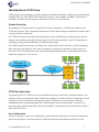
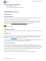
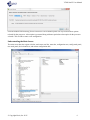
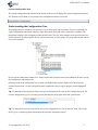
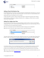
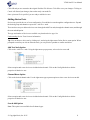
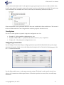
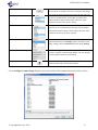
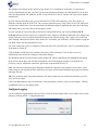
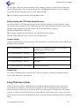
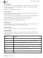
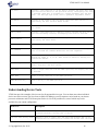
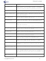
VTOS Scan™ User Manual December 11, 2015 VTOS Scan™ User Manual Table of Contents Introduction to VTOS Scan .......................................................................................................................................3 System Overview ................................................................................................................................................................... 3 VTOS Scan Operation .......................................................................................................................................................... 3 VTOS Scan Suggestions ........................................................................................................................................................ 4 VTOS Scan Software Requirements .................................................................................................................................... 5 Using VTOS Scan Software ......................................................................................................................................5 Getting Started ...................................................................................................................................................................... 5 Understanding the Configuration Tree ............................................................................................................................... 8 Adding a Board Initialization Step ...................................................................................................................................... 9 Adding Pin Configuration Data ........................................................................................................................................... 9 Adding Device Tests ............................................................................................................................................................ 11 View Options ........................................................................................................................................................................ 12 Configuring Connections .................................................................................................................................................... 12 Configure Logging ............................................................................................................................................................... 14 Understanding the VTOS Scan Home Directory .............................................................................................................. 15 Using VTOS Scan Actions ......................................................................................................................................15 Action Types ........................................................................................................................................................................ 16 Accessing Actions ................................................................................................................................................................ 16 Configure Actions Dialog .................................................................................................................................................... 16 Actions Available ................................................................................................................................................................. 17 Understanding Device Tests ....................................................................................................................................18 Using the Run Mode ................................................................................................................................................20 Loading and Running VTOS Scan Firmware................................................................................................................... 21 Run Mode Steps ................................................................................................................................................................... 21 Exporting Test Configurations ...............................................................................................................................24 Exporting your Test Configuration to a Kozio Script File .............................................................................................. 24 Exporting your Test Configuration to a TestStand Sequence File .................................................................................. 24 Contact Information ................................................................................................................................................25 About Kozio, Inc. .....................................................................................................................................................25 © Copyright Kozio, Inc. 2015 2 VTOS Scan™ User Manual Introduction to VTOS Scan VTOS Scan provides everything you need to configure and validate the hardware interfaces of your board design; including GPIO, I2C, SPI, UART, USB, Ethernet, PCI Express, CAN, SD/MMC, and SDIO. VTOS Scan is a standalone verification tool that integrates with Kozio's vAccess™ for automated test. System Overview The standalone VTOS Scan system is comprised of two major components: VTOS Scan host software, and VTOS Scan firmware. These components communicate with each other through a communication channel such as a serial port or JTAG connection. The VTOS Scan firmware runs from the on-chip memory of your embedded system, allowing you to fully test hardware buses and devices using the embedded processor. The firmware provides a rich set of capabilities for configuring, testing, and troubleshooting your hardware board design. The VTOS Scan host software runs on a Windows PC, and provides two main functions: a tool for configuring and verifying new test sequences; and a tool for exporting test sequences for automatic use with various test executives. The VTOS Scan firmware can also be driven programmatically from an automated production test framework using Kozio’s vAccess DLL. VTOS Scan Operation The primary purpose of VTOS Scan is to create a board test sequence, interactively validate the sequence, and export the sequence for automated testing. Each board test sequence is stored in a separate configuration file and is linked to a processor architecture and a particular option. VTOS Scan uses various options so that the embedded firmware accompanying that option is small enough to fit into on-chip memory. A current list of options are: Base (which includes GPIO, I2C, SPI, and UART), CAN, Ethernet, PCI, USB 2.0 Device, USB 2.0 Host, and USB 3.0 Host. New Configuration To start a new project, create a new configuration, a process that will prompt you to select the correct processor architecture and option. A new license may be required for each processor architecture and option. A new © Copyright Kozio, Inc. 2015 3 VTOS Scan™ User Manual configuration contains a tree structure with a board, board initialization, pin configuration, and one or more bus groups. Board Initialization The next step is to specify if you want to run a script file that prepares the board for proper operation. This script may disable a watchdog timer, configure GPIO signals, enable clocks, configure power, or other board specific steps. If this step is enabled, the board initialization script will be executed once a new connection is established. Pin Mux File The next step is to specify which pin mux file you will be using for your custom circuit board design. VTOS Scan allows you to import a pin mux files that was generated by another tool, a pin mux tool commonly distributed by processor manufacturers. Device Tests For each bus group, the configuration tree will contain one or more channels. This varies based on the processor architecture. For each channel, you add as many device tests as desired. For certain busses, such as I2C and PCI, you can use the scan and add feature to automatically add a device test for every device discovered. Special Actions If your embedded system design requires special operations, such as driving a GPIO signal low before communicating with an I2C device, you can add actions. All nodes of the tree, except for the Configuration and Board nodes, have the option to add Setup Actions and Cleanup Actions. A special dialog allows you to add as many setup and cleanup actions as desired. The list of possible actions will vary based on processor architecture and tool option. Run Command VTOS Scan also allows you to run your test sequence to validate it. In order to run your test sequence, you must update VTOS Scan connections to specify device connection information. The connection information is stored in a vaccess.ini file that specifies one or more fixtures, and for each fixture, which firmware you have running on your embedded target and the communications channel. Lastly, you must have that firmware image loaded and running on your embedded device. The remainder of this user manual provides step by step instruction on completing all of the tasks associated with creating, testing, and exporting your own test sequences for your custom embedded system. VTOS Scan Suggestions Name Field Every node of the VTOS Scan configuration tree contains a Name field. You can use this field to store labels that help you identify your particular board configuration information. For device test nodes, the Name label is also included as a comment in the test command being executed. When exporting to a Kozio script file, the Name label will appear in the console output after the command is run. When exporting to a TestStand sequence, the Name label will appear in the label TestStand displays for each command. © Copyright Kozio, Inc. 2015 4 VTOS Scan™ User Manual VTOS Scan Software Requirements Microsoft Windows XP, 7, 8. Serial port or other supported communication device Using VTOS Scan Software Getting Started Installing the Software VTOS Scan is included with the VTOS Tools installer, which installs VTOS Scan™, VTOS DDR™, vAccess™, and other tools. To install the software, run the latest VTOS Tools installer. The installer creates a program icon for launching the software under your Windows Start menu and places an icon on your desktop. It also installs software resources and DUT firmware to a home directory in your User Profile directory. See Understanding the VTOS Scan Home Directory for further details. (VTOS Scan Icon) Configuring the Software The first time you launch VTOS Scan, it will guide you through a couple steps to configure the software for your system. Installing a License VTOS Scan software requires a valid license for full activation and for communications with a target device. A single license enables one instance of the software to be connected to a target for a specific embedded system architecture. Contact [email protected] to obtain a license for your use. To install a license, launch VTOS Scan. From the File menu, click Install License. Use the file selection dialog to select your license file. VTOS Scan will install and validate the selected license. Creating a New Configuration VTOS Scan requires a board configuration which is used to store board initialization information, pin mux information, device test information, and command actions. You must create a new configuration in order to store device test information. A different configuration file is created for each processor and option selection. Available options include creating test configurations for: Base (GPIO, I2C, SPI, UART; Ethernet; PCI; CAN; and USB; To create a new configuration, select File then New from the main menu. Tip: You can use Ctrl + N to launch the Product Selector and create a new board configuration. © Copyright Kozio, Inc. 2015 5 VTOS Scan™ User Manual From the Product Selector dialog, choose a Processor. The available options will vary based on those options released for that processor. A description is presented along with notes particular to that option for the processor selected. Click on OK to create a new configuration. Understanding the Main Screen The main screen has nine regions: title bar, main menu, tool bar, status bar, configuration tree, config mode panel, run mode panel, device button bar, and current configuration data. © Copyright Kozio, Inc. 2015 6 VTOS Scan™ User Manual Title Bar The title bar runs across the top of the screen. It displays the product name and revision. Main Menu The main menu runs horizontally below the title bar. Main menu items are displayed with their hot key shown to the right of the item. Tool Bar The tool bar is just below the main menu and provides several single-click shortcuts for commonly used tasks. Status Bar The status bar displays status along with a spinner that only appears when connecting or running commands. Configuration Tree The configuration tree is the panel on the left just below the tool bar. Your board configuration data is displayed in the configuration tree. The configuration tree, in conjunction with the Config Mode panel, is used to specify a pin mux file, add and modify device tests, and add and modify actions. Config Mode Panel The configuration mode panel is visible when the Config Mode tab is clicked. This panel has a top section and bottom section. The top section displays all available fields for the node selected in the configuration tree. The bottom section displays additional information about the field selected. Some fields display an additional pop-up dialog button or pull-down list when clicked on. Run Mode Panel The run mode panel is visible when the Run Mode tab is clicked. This panel is a console window. VTOS Scan output is displayed in the console window. See Using the Run Mode, once you are familiar with creating test configurations. Device Button Bar The device button bar provides several shortcut buttons to aide in creating and adjusting your desired programming sequence. Use the buttons to copy, delete, move up, or move down the selected device node. (All device nodes use the same icon as their identifier. ) © Copyright Kozio, Inc. 2015 7 VTOS Scan™ User Manual Current Configuration Data The current configuration data runs across the bottom of the screen. It displays the current configuration opened. The file name will be blank if you created a new configuration but have not saved it. Understanding the Configuration Tree The configuration tree maintains a pin mux file, a list of device tests, and test actions. The tree is organized as a single Configuration node which contains a single Board node. Each node can be expanded or collapsed. The Board node contains a Pin Configuration node and SOC node. The SOC node contents varies based on processor architecture and VTOS Scan option chosen, but will contain one or more groups. The group nodes in turn contain one or more channels. Device tests are added at the channel level. Setup Actions and Cleanup Actions can be added for all nodes except the Configuration and Board nodes. Selecting a node in the configuration tree, with the Config Mode tab selected, displays all of the properties available for that node. Use the Config Mode panel to update the value of a given property for the highlighted node. Tip: To determine which option you choose for a given configuration file, click on the Configuration node. The current Configuration Type is a read-only property that displays the program name and option chosen. Tip: To determine the processor you choose for a given configuration file, click on the SOC node. The current SOC Type is a read-only property that displays the processor architecture chosen. © Copyright Kozio, Inc. 2015 8 VTOS Scan™ User Manual Adding a Board Initialization Step The Board Initialization node includes a property specifying the board initialization script file that you want to use for this configuration. This script will be executed once after a successful connection. A board initialization file is optional and this step will be skipped if no file is specified. A board initialization script file is useful for taking required steps for proper board operation. Some examples include disabling a watchdog timer, enabling certain power rails, or configuring a CLPD. This file is an ASCII file that can be edited by hand. Adding Pin Configuration Data The Pin Configuration node includes a property specifying the pin mux file that you want to use for this board configuration. A pin mux file is a Kozio script file that configures the pins for your circuit board design. This file is an ASCII file that can be edited by hand or generated. When a file is entered, that file will be included and used when executing your test configuration. Note: Device tests will often fail without a proper pin mux file specified and included. You must use the Pin Mux File Selector to choose which file you want to use. You cannot edit the filename field directly. To select a new pin mux file, click on the Pin Mux File property, and then click on the ellipses button. Use the Browse button to select an existing Kozio pin mux file. Use the Import button to generate a new Kozio script file from an existing pin mux file created through a third-party utility. Most processor manufacturers provide a free pin mux utility, and VTOS Scan will automatically convert that file into a Kozio script format. Tip: If you are using a new pin mux tool not currently supported by VTOS Scan, email details about the new tool and an example pin mux file to [email protected]. © Copyright Kozio, Inc. 2015 9 VTOS Scan™ User Manual Import a Pin Mux File After clicking on Import, you are prompted to select your existing pin mux file. The file generated by the processor manufacturer’s tool. VTOS Scan will parse the file to determine what type of file you selected. A dialog box prompts you with the information discovered. If the file type is unsupported, a dialog indicates that no converter is available for the selected file type. Click OK to continue. Once the import is complete, you will be prompted to save the file. Note: The input file name is used with a new extension of .ksc. Kozio uses the .ksc extension to indicate the file is a Kozio script file. After entering a filename and clicking on OK, a pin mux import report is displayed. © Copyright Kozio, Inc. 2015 10 VTOS Scan™ User Manual Click OK and you are returned to the original Pin Mux File Selector. Click OK to save your changes. Clicking on Cancel will discard your changes, but not the newly converted file. Once a pin mux file is specified, you are ready to add device tests. Adding Device Tests Device tests provide the core of a test configuration. You add device tests through the configuration tree. Expand the desired group and channel to expose the <Add Test> node. There are three ways to add new devices tests: through the Add Test node, through the channel menu, and through the scan and add option. The type and number of device tests available vary based on device type. See Understanding Device Tests for more information. Tip: You can delete a device test by clicking on it, and using the right-mouse Delete Device menu option. When prompted to confirm you wish to delete the node, you can press the spacebar to confirm and delete. Add Test Node Option Click on the <Add Test> node. Using the right-mouse pop-up menu, select a device test to add. Select an option and a new device test is added to that channel. Click on the Config Mode tab to edit the properties of that device test. Channel Menu Option Click on the desired channel node. Use the right-mouse pop-up menu option to select a new device test to add. Select an option and a new device test is added to that channel. Click on the Config Mode tab to edit the properties of that device test. Scan & Add Option Note: This option is not available for all channel types. © Copyright Kozio, Inc. 2015 11 VTOS Scan™ User Manual Click on the desired channel node. Use the right-mouse pop-up menu option to select one of the available “Scan & Add” menu options. You must be connected to a target in order to use this option successfully. This option runs a scan command on the embedded device and uses the results to automatically add discovered devices. Select an option and a scan is performed and a new device test is added for all discovered devices. Click on one of the devices added and click on the Config Mode tab to edit the properties of that device test. View Options Use the View menu options to expand or collapse the configuration tree view. Expand All – fully expands the configuration tree view. Expand All With Children – expands all nodes that have devices, tests, or operations. Collapse All – fully collapses the configuration tree view. Configuring Connections Use the Configure Connections dialog to configure parameters required for the Run Mode and to specify target connection information. Obtain access to this dialog by selecting the tool bar Connections button ( ) or the File → Connections menu item. Use this dialog to add, remove, or alter target connection settings. This dialog is used to specify how the host software will communicate with the target firmware. Follow the steps below to create, delete, or modify target connections. © Copyright Kozio, Inc. 2015 12 VTOS Scan™ User Manual Click on the Add button This button adds a new blank target connection. You must fill in the four options for Product, Processor, Connection, and Settings. Select a Product This option determines which firmware image the host and target will use for communications. Each product is installed with different firmware images. If this setting is incorrect, target command execution errors will be reported. Select a Processor This option also determines which firmware image the host and target will use for communications. Each processor is installed with different firmware images. If this setting is incorrect, target command execution errors will be reported. Select a Connection This option determines the type of connection used for host to target communications. The Settings option is tied dirctly to this setting. Changes made to Connection will also change Settings. Select or enter Settings Click on a Settings pull-down, or use the right-mouse menu, to access the Configure Comm Settings dialogue. The new dialogue is used to update connection specific details. Click on the Delete icon Click here to remove a target connection. You cannot remove a connection when only one connection remains. Use the Configure Comm Settings dialogue to specify the details of the communications port you have chosen. © Copyright Kozio, Inc. 2015 13 VTOS Scan™ User Manual This dialogue varies based on the Connection type chosen. For a CodeWarrior connection, you will need to specify a TAP Identifier. Select your TAP Type from the pull-down and enter your TAP Identifier. You can also enter the fully qualified TAP Identifier, such as “cwtap: 00:04:9F:03:AE:C0” and the TAP Type will be updated automatically. If you are having connection issues, you can alter the JTAG TCK (clock frequency) value. This value is in Kilohertz. Slowing down the JTAG TCK can overcome connection issues. Using a faster JTAG TCK setting can result in faster transmissions. You can experiment with different settings by adjusting this value, then connecting and running tests to see if the current clock frequency works. If you are running on a processor that uses the Reset Configuration Words, you can select True for RCW Override and then fill in the sixteen (16) 32-bit RCW values. When set to True, an additional step is taking when loading firmware to first override the default RCW and use the filled in settings. This is often a very useful step when working with brand new boards. Once the RCW is overridden, you can then use VTOS Program to program new RCW values into the defined RCW source. For Serial connections, type in a COM port or Scan and select from a pull-down list. The list is populated after the Scan button is clicked on. Click on Scan to refresh the list of available serial ports or TAP connections. Click on Save to save all modifications and return to the Configure Connections dialogue. The Run Mode option uses the currently selected connection, which is indicated by the highlighted radio button. In the screen capture above, the selected configuration is for VTOS Program, running on an QorIQ P1xxx processor, using a CodeWarrior connection, specifically cwtap:00:04:9F:03:AE:C0. Note: For non-Serial connection types, additional information is provided in the product’s release notes. Serial baud settings are not required for Seral connections since these are determined automatically by the host software and target firmware. Tip: You can define many connections and then select which connection (also called fixture number) to use for your various test setups. Click on the Save button to store all connections. This information is stored in a file on your computer. Clicking on Cancel will not save any changes made. Configure Logging Use the Configure Logging dialog to specify a file to which all console output will be saved. Obtain access to this dialog by selecting the File → Logging menu item. © Copyright Kozio, Inc. 2015 14 VTOS Scan™ User Manual You can capture VTOS Scan console output to a log file. Adding a filename will capture all text written to the console window to that file. The log is an ASCII text file. Use the Browse button to browse to an existing file. Use the View button to bring the log file up in your default text editor. Tip: You can directly edit the filename in the Log File text field. Understanding the VTOS Scan Home Directory The installer creates a VTOS Scan home directory in your User profile directory. The home directory contains software and firmware resources for the VTOS Scan system. The location of the home directory is stored in the %KOZIO_USER_HOME% environment variable. The VTOS Scan directory is located at %KOZIO_USER_HOME%\VTOS_Scan. Tip: To quickly navigate to the home directory, open Windows Explorer and paste %KOZIO_USER_HOME%\VTOS_Scan in as your new path location. Firmware Images VTOS Scan firmware images are stored in the VTOS_Scan directory. VTOS Scan firmware images adhere to the following naming convention: vtos.<system-architecture>_scan.elf ELF object file. Compatible with a wide variety of loaders, including many JTAG-based loaders vtos.<system-architecture>_scan.img U-Boot compatible vtos.<system-architecture>_scan.srec Motorola S-Record vtos.<system-architecture>_scan.bin Raw binary vtos.<system-architecture>_scan.bin.MLO TI self-booting binary file. Example Files A few sample configuration files are stored in the VTOS_Scan directory. VTOS Scan configuration files are stored as XML files with an .xml extension. Using VTOS Scan Actions VTOS Scan Actions expose the commands that are provided through the VTOS Scan firmware and can be executed during a test sequence. These actions were designed to allow the addition of special configuration actions required on a per device basis. If you have an I2C device that requires a GPIO signal to be driven high before use, or requires a register write before use, you can add new actions before or after a group or device test. Actions can also be used to create troubleshooting steps, or special tasks required during regression or production testing. © Copyright Kozio, Inc. 2015 15 VTOS Scan™ User Manual Tip: If a particular list of actions gets too long to easily maintain through the VTOS Scan GUI, you can also store you list of actions in a script file and use the Run Command to include and execute your unique set of actions. Action Types Two types of actions are provided: Setup Actions that are executed before a group or device test, and Cleanup Actions that are executed after a group or device test. Every node in the configuration tree, except the Configuration and Board nodes, have Setup Actions and Cleanup Actions. Tip: A brief view of the list of actions added is visible when you select a node and view the Config Mode panel. Accessing Actions Actions are added, deleted or modified through the Configure Actions dialog. Click on the desired node in the configuration tree and then click on the Config Mode panel. To add an action, click on either the Setup Action or Cleanup Action field. Once selected, a new ellipses button appears along the rightmost edge of the field. Click on the button to access the Configure Actions dialog. Configure Actions Dialog Use the Configure Actions dialog to add, delete, modify, or reorder your list of actions. The actions are executed in the order presented, from top to bottom. The Configure Actions dialog has three main regions: Actions Available, Actions to Perform, and Action Properties. © Copyright Kozio, Inc. 2015 16 VTOS Scan™ User Manual Actions Available This section provides a list of actions that can be added to your configuration. They will be executed before or after the node you originally selected in the configuration tree. To add a new action, click on your choice and click on the Add Action button. Tip: Double-click on an action to automatically add it. Actions to Perform This section provides a list of actions that will be executed from top to bottom. Click on an action to select it. Once selected, the Action Properties panel is updated. To move an action up or down, after you have added at least two actions, click on the action and then click on the up-arrow or down-arrow buttons. The reorder buttons are located to the right of this panel. To remove an action, click on the action, and then click on the Remove Action button. Tip: You can also use the delete key to delete the highlighted action. Action Properties This panel display the properties of an action and allows you to edit those properties. The field at the bottom of this panel provides additional information regarding the highlighted property. Saving Your Actions To save your updates, click the OK button. Clicking on the Cancel button will discard all modifications. Actions Available The list of actions available for adding to your test sequence varies based on your chosen processor architecture and VTOS Scan option. Below is a list of all possible actions, some of which may not be available for your current configuration. Action Description Bit Set Sets a bit within an 8-bit, 16-bit, or 32-bit value in memory. Bit Clear Clears a bit within an 8-bit, 16-bit, or 32-bit value in memory. Command Timeout Set the desired command timeout in milliseconds. Delay Ms Delay for the specified number of milliseconds. Delay S Delay for the specified number of seconds. GPIO Read Read a GPIO signal and display the value read. GPIO Write Drive a GPIO signal high or low. © Copyright Kozio, Inc. 2015 17 VTOS Scan™ User Manual I2C Read Performs a read operation to an I2C device. Returns the 8-bit data value read from the I2C device at the specified offset, and displays the value if selected. Read data is returned as a single parameter onto the data stack. For multiple byte reads, data is packed in big-endian format. I2C Write Performs an I2C write to the I2C device specified. Data written is specified by the Data and Data Width fields. I2C Dump Reads data from the specified device address and displays the data to the console. Memory Read Performs a read operation to a memory location. Returns the data value read from the memory location, and displays the value if selected. Memory Write Performs a memory write to the location specified. Data written is specified by the Value field. Memory Dump Reads data from the specified address and displays the data. Run Command Runs any Kozio script command available. You can use “include script file” to include new command definitions and test sequences. SDMMC Set Width Sets the SD/MMC/SDIO bus width. The user specifies the channel and desired bus width (1, 4, or 8). This action is useful to testing all possible bus widths. UART Configure Configures a UART device. Specify channel number, baud rate, data bits, parity, stop bits, and flow control. UART GetC Writes a single character form the UART specified, and display the value if selected. UART PutC Writes a single character to the UART specified. UART WriteString Write a string to the UART specified. Understanding Device Tests VTOS Scan provides a number of device tests for all supported device types. You can learn more about individual device tests in this section. The list of tests available for adding to your test sequence varies based on your chosen processor architecture and VTOS Scan option. Below is a list of all possible test, some of which may not be available for your current configuration. Device Test Description Ethernet PHY Exists Test Execute a test to verify that the specified Ethernet PHY can be accessed correctly, proving that it exists. Ethernet PHY Verify Test Execute a test to verify that the specified Ethernet PHY can be accessed and its identification information matches what the user © Copyright Kozio, Inc. 2015 18 VTOS Scan™ User Manual provided. MAC Loopback Test Loopback internally in the Ethernet controller, or MAC (Media Access Control). Tests the internal operation of the Ethernet controller and does not exercise any signaling on the board. PHY Loopback Test Loopback internally at the Ethernet PHY. Tests the MII data path connection between the Ethernet controller and the Ethernet PHY. External Loopback Test Loopback externally using a loopback plug. Tests the full data path, including the Ethernet controller, Ethernet PHY, and the copper/fiber transceivers. GPIO Loopback Test Execute a test that drives a signal on an “out” pin and verifies that the signal is received on an “in” pin. GPIO Verify Test Execute a test that reads a signal on a user specified pin and compares that value against a user specified expected value. I2C Bus Scan Non-destructive scan of all possible addresses on a specified I2C bus. Usage: <bus> i2c.bus.scan Where <bus> is the I2C bus number. Specify -1 to scan all buses. I2C Device Exists Test Execute a test to verify that the specified I2C device can be accessed correctly, proving that it exists. I2C Verify Test Execute a test to read a data value from the I2C device and compare it against a user specified value. PCI Device Exists Test Execute a test to verify that the specified PCI device can be accessed correctly, proving that it exists. PCI Verify Test Execute a test to read the vendor id and device is from the PCI device and compare it against a user specified values. SDIO Device Exists Test Execute a test to verify that the SDIO device on a configured channel can be accessed correctly, proving that it exists. SDIO Verify Test Execute a test to verify that the specified SDIO device can be accessed and its identification information matches what the user provided. SDMMC Device Exists Test Execute a test to verify that the SD/MMC device on a configured channel can be accessed correctly, proving that it exists. SDMMC Verify Test Execute a test to read the Manufacturer Id, OEM Id, and Capacity from a configured SD/MMC device and verify that it matches the values provided by the user. During initial test development, run this command once and the correct values will be displayed to the user. SDMMC Checksum Test Execute a test to calculate an MD5 checksum over a specified block count. The user specifies Start Block, Block Count, the correct 32 © Copyright Kozio, Inc. 2015 19 VTOS Scan™ User Manual character MD5 checksum value, and a Verify Checksum flag. During initial test development, set the verify flag to false and the test will return the correct 32 character MD5 checksum value. SPI Device Exists Test Execute a test to write to a SPI device, and verify that data can be read from that device. SPI Verify Test Execute a test to write bytes to a SPI device, read data from that device, and verify that the correct bytes and number of bytes were read. Tip: set <data_verify> to FALSE to display the current JEDEC-ID information returned by the serial flash device.." SPI Flash Device Exists Test Execute a test to verify that a Serial Flash device exists. SPI Flash Verify Test Execute a test to verify the Manufacturer Id, Memory Type, and Memory Capacity of a Serial Flash device. Verifies the JEDEC-ID from a SPI serial flash device. The returned JEDEC-ID is compared against the specified manufacturer and memory part information. UART Device Exists Test Execute a test to write bytes to a UART device, and read bytes from the same UART device. The test passes is the number of bytes read matches the expected count of bytes read. UART Loopback Test Execute a test to write data to a UART device, read data from the same UART device, and verify the data values. UART Verify Test Execute a test to write bytes to a UART device, and read bytes from the same UART device. The test passes is the number of bytes read matches the expected count of bytes read and a data compare of the bytes also matches the specified read compare bytes. UART Bluetooth Device Exists Test Queries the BD_ADDR of the Bluetooth controller on the specified channel. The returned BD_ADDR is displayed on the console. Note: The serial port parameters are automatically setup to match the Bluetooth specification (8 data bits, no parity, 1 stop bit, RTS/CTS flow control). UART Bluetooth Verify Test Queries the local version information for the Bluetooth controller connected to the specified UART channel. The returned version information is optionally compared against the specified version information. Tip: set <data_verify> to FALSE to display the current version information returned by the Bluetooth controller. Using the Run Mode The VTOS Scan software provides a user interface for creating test sequences that are performed by the VTOS Scan firmware running on your embedded device. © Copyright Kozio, Inc. 2015 20 VTOS Scan™ User Manual Use the Run Mode to validate that your device tests are configured properly. Using the Run Mode requires a valid connection, a working communications channel to your embedded device, and the VTOS Scan firmware running on your embedded device. Note: You can use the VTOS Scan software to create new test sequences without having to interact with VTOS Scan firmware running on your embedded device. In this mode, you create a configuration and export it for testing with a test executive such as vAccessTest.exe or TestStand. Loading and Running VTOS Scan Firmware The VTOS Scan firmware must be loaded and running on your embedded device. To load the VTOS Scan firmware use a JTAG programmer, your boot loader, processor specific boot methods (USB, SD Card, Serial), or similar process. The VTOS Scan firmware images are installed in the VTOS Scan home directory on your host PC. See Understanding the VTOS Scan Home Directory for further details. Please see the appropriate Application Note for your system architecture for details on how to load and execute the VTOS Scan firmware image on your board. These application notes are available on ww.kozio.com under Resources → Application Notes. Note: Many of the application notes were written to cover loading VTOS DDR firmware, but they still apply to loading all firmware types. Run Mode Steps The Run Mode has three main steps that must be executed in order. The steps are: Connect, Run, and Disconnect. Connect Use the Tools menu option to run the Connect command. You can also use the Connect button on the tool bar. This step requires a run-time (vAccess™) license. One license is provided with a VTOS Scan™ purchase. This step uses the connection information specified under Configuring Connections. This step will attempt to establish a connection with the vAccess.dll and launch a process that communicates with the VTOS Scan firmware. This step can succeed even if you do not have a target connected, but you will not be able to successfully run any test commands. Once you are connected, this button is greyed out and the Run and Disconnect options become available. If you connection attempts fails, a failure message is displayed in the status portion of the tool bar. The error code displayed is taken from the vAccess header file (vAccess.h). Additional information on the failure may be obtained from this header file. Some common connection errors are: 2 - VACCESS_CONFIGURATION_ERROR. Check you connection settings and your communications channel. © Copyright Kozio, Inc. 2015 21 VTOS Scan™ User Manual 4 - VACCESS_ENV_ERROR. Check your KOZIO_USER_HOME and KOZIO_VTOS_TOOLS environment variables to make sure they are set properly. These are configured automatically by the installer so it is possible to re-install VTOS Scan to set them up again. 5 - VACCESS_INI_FILE_ERROR. Check to make sure you INI file is formatted correctly. An example file is distributed with the VTOS Tools Installer. 6 - VACCESS_LICENSE_ERROR. Check to make sure you are not running more copies of VTOS Scan than you have licenses for. Also check you license file or license server. Note: It is critical that the firmware running on your device matches the firmware file specified in your Connections settings. If not, some commands may report failures. Run This option is only available after you have successfully connected. There are several different ways to run your test configuration. The ways vary from running all test configuration steps to only running a single device test command. Note: There are two Tools menu options to display the VTOS PC Version and also the VTOS DUT Version. These are useful tests to verify communications with vAccess and the VTOS Scan firmware respectively. Note: There is also a Tools menu option to Read Console Data. This command will read any pending console data, but in most cases will not display anything if there is no console data. This command may be useful for debugging when commands time out or fail. The available run modes are: All – Run everything. o Use the Tools menu option Run or tool bar Run button. This option will run the entire test sequence from top to bottom. Board – Run everything. o Click on the Board node and use the right-mouse Run option. This will run the entire test sequence since it runs the Board node and all of its child nodes. Pin Configuration – Run only the pin mux file. o Click on the Pin Configuration node and use the right-mouse Run option. This will run the Pin Configuration setup actions, the pin mux file, and then the Pin Configuration cleanup actions. SOC – Run the SOC and all of its children. o Click on the SOC node and use the right-mouse Run option. This will run the SOC setup options, run all SOC child nodes, and then the SOC cleanup actions. Group – Run a group and all of its children. o Click on any one of the bus group nodes and use the right-mouse Run option. This will run the group’s setup options, run all of the group’s child nodes, and then the group’s cleanup actions. Channel – Run a group’s channel and all of its children. o Click on any one of the channel nodes and use the right-mouse Run option. This will run the channel’s setup options, run all of the channel’s child nodes, and then the channel’s cleanup actions. © Copyright Kozio, Inc. 2015 22 VTOS Scan™ User Manual Device Test – Run a single device test. o Click on any one of the device tests and use the right-mouse Run option. This will run the device test setup options, run the device test, and then the device test cleanup actions. After executing a run sequence, the Run Mode console window is selected and the console window is updated with output received from the VTOS Scan firmware. Some common run errors are: 13 - VACCESS_EXECUTE_COMMAND_FAILURE. The command failed to execute properly. 14 - VACCESS_EXECUTE_COMMAND_ABORT. The command was aborted. 16 - VACCESS_EXECUTE_COMMAND_TIMEOUT. The command timed out. This will occur when the firmware is not loaded or running. Disconnect This option is only available after you have successfully connected. This step will disconnect your from vAccess and free up your license. Use the Tools menu option to run the Disconnect command. You can also use the Disconnect button on the tool bar. Note: You can Connect and Disconnect as many times as desired. Understanding the Run Mode Console Window After executing a run sequence, the Run Mode tab is selected and the console window is updated with output received from the VTOS Scan firmware. © Copyright Kozio, Inc. 2015 23 VTOS Scan™ User Manual A scroll bar becomes available once the number of lines added to the console window is larger than the display area. Right-mouse menu options are available to copy selected test, copy all, select all, and to clear all. Tip: You can also log the contents of the console window to a file. See Configure Logging. Exporting Test Configurations One of the primary values of the VTOS Scan GUI is to create a test configuration and export it for automated testing. Two export options are provided: export to a Kozio script file and export to a NI TestStand Sequence. Exporting your Test Configuration to a Kozio Script File To export your entire test sequence to a Kozio script file, click on File → Export → Kozio Script File. This step will traverse your test configuration data and create a Kozio script file. The output is an ASCII file that you can view in any text editor. Note: You can use vAccessTest.exe to execute your exported test sequence. vAccessTest.exe is a simple example program provided to demonstrate vAccess.dll features. vAccessTest.exe has a command line option and is described in greater detail in the vAccess™ User Manual. vAccessTest.exe is provided free of charge through the VTOS Tools installer. Exporting your Test Configuration to a TestStand Sequence File To export your entire test sequence to a TestStand sequence file, click on File → Export → NI TestStand Sequence. This step will traverse your test configuration data and create a sequence file. The output is a binary file that you can load directly into NI’s TestStand. © Copyright Kozio, Inc. 2015 24 VTOS Scan™ User Manual Note: Once you have your new sequence file loaded into TestStand, each new export will cause TestStand to prompt you that the file has changed. Running VTOS Scan and TestStand side by side provides a very efficient test development environment. Contact Information For technical support questions, please email [email protected]. For sales or other information, Kozio, Inc., +1 (303) 776-1356 x1, [email protected], www.kozio.com About Kozio, Inc. Kozio, Inc. is a software technology company focused on providing superior embedded tools solving a variety of challenges during the design, production, and support of embedded devices. With its wide range of embedded tools, Kozio offers solutions to aerospace, automotive, consumer, industrial, military, medical, networking, and wireless markets. Kozio has been crafting embedded software since 2003 and has served the needs of thousands of engineers working for hundreds of companies, from the smallest to the largest. Kozio’s line of embedded tools include everything you need to configure, test, and tune DDR memory; identify interconnect faults and component placement problems on your printed circuit board; and program on-board devices such as NAND Flash, NOR Flash, eMMC, FPGAs, and other programmable devices. Kozio’s tools are reusable across a family of SoC-based designs and reusable across teams © 2015 Kozio, Inc. All rights reserved worldwide. Kozio and the Kozio logo are registered trademarks of Kozio, Inc. VTOS, VTOS Scan, VTOS Scan, VTOS Program, and vAccess are trademarks of Kozio, Inc. All other trademarks are the property of their respective owners. © Copyright Kozio, Inc. 2015 25