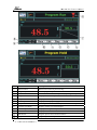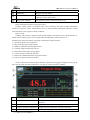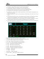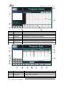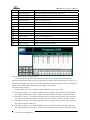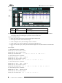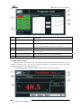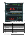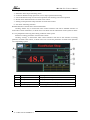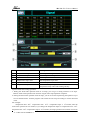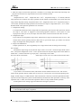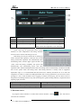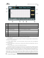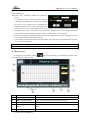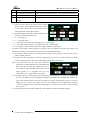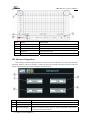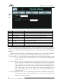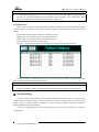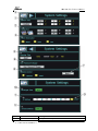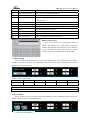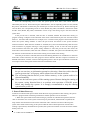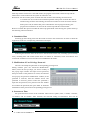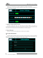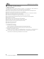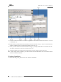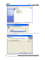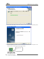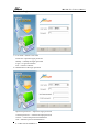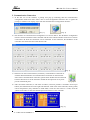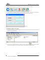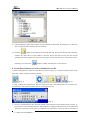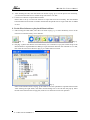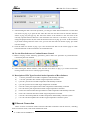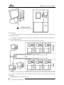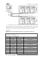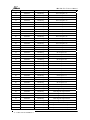
1
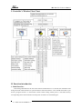
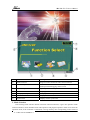
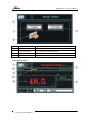
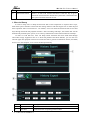
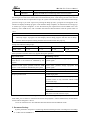
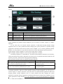
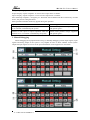
V:UMC1100.2.0.USER.E1.0 UMC1100 Series High and Low Temperature Program Controller User’s Manual (V2.0) ——Shanghai Becca Electronic Technological Co., Ltd.—— UMC1100(V2.0)User’s Manual Contents I. Controller’s Window Flow Chart……………………………………………………………… 2 II. Detailed Functions Introduction…………………………………………………………… 2 1. Initial Interface……………………………………………………………………………… 2 2. Mode Selection……………………………………………………………………………… 3 3. Program Control……………………………………………………………………………… 4 4. Fixed Value Control…………………………………………………………………………12 5. Real-time curve………………………………………………………………………………18 6. History Curve…………………………………………………………………………………19 III. Advanced Operation……………………………………………………………………………21 1. Historical Dump………………………………………………………………………………22 2. Document Backup……………………………………………………………………………24 3. Manual Debugging……………………………………………………………………………25 4. Fault Record…………………………………………………………………………………27 IV. System Setting………………………………………………………………………………28 1. Time Setting…………………………………………………………………………………29 2. Pre-set Boot…………………………………………………………………………………30 3. Power Failure Recovery……………………………………………………………………31 4. Cumulative Run………………………………………………………………………………31 5. Modification of User Privilege Password……………………………………………………31 6. Screensaver Time………………………………………………………………………………32 7. IP Address Settings, DHCP Function………………………………………………………32 8. Touch Calibration…………………………………………………………………………32 Ⅴ. Product Information…………………………………………………………………………33 Ⅵ . UMC1000_User Host Software ……………………………………………………………33 1. Software Functions…………………………………………………………………………33 2. Communication Settings………………………………………………………………………33 3. Software Installation…………………………………………………………………………34 4. Software Login……………………………………………………………………………37 5. Communication Connection……………………………………………………………………38 6. Use the Host Software to Export Files from the Controller……………………………………39 7. Examples of History Playback…………………………………………………………………39 8. Use the Host Software to Create or Modify Process file………………………………………40 9. Use the Host Software to Play back Historical Data……………………………………………41 10. Use the Host Software to Conduct Remote Control…………………………………………42 11. Description of File Types Involved in the Operation of Host Software………………………42 Ⅶ . Ethernet Connection………………………………………………………………………42 Appendix:List of Correspondence Address………………………………………………44 V:UMC1100.2.0.USER.E1.0 -1- UMC1100(V2.0)User’s Manual I. Controller’s Window Flow Chart II. Function introduction 1. Initial Interface After being electrified for the first time and self examination of 15 seconds, the instrument will change from the initial interface to system function selection interface. Users should notice that if you choose “program control” or “fixed-value control” before cutting off the power, it will enter directly corresponding main control interface of last power off when it is electrified again. V:UMC1100.2.0.USER.E1.0 -2- UMC1100(V2.0)User’s Manual Item Name Description ① Mode selection Program control and fixed-value control selection ② Advanced operation Include advanced renewal/ history dump/document backup/manual debugging/ faults record ③ System setup System parameters setup ④ Product information Display product information ⑤ Company name/product model Company name and product model ⑥ Product version number Display version number ⑦ System time Display current system time 2. Mode Selection After clicking mode selection button in function selection interface, it goes into operation mode selection interface, which includes fixed-value operation and program operation. After users select the operation mode, if the controller is electrified, it will go directly into corresponding control mode of V:UMC1100.2.0.USER.E1.0 -3- UMC1100(V2.0)User’s Manual last power off. Item Name Description ① Program control Enter program operation mode ② Fixed-value control Enter Fixed-value operation mode ③ Mode Graphic Display control of mode icons ④ Return Return to function selection interface 3. Program Control V:UMC1100.2.0.USER.E1.0 -4- UMC1100(V2.0)User’s Manual Item Name Description ① Return button Return to the menu of previous step ② Program operation status Current program operation status ③ Curve check Real-time curve/curve history check, ④ Temperature SV value Display current set temperature value ⑤ Temperature PV value Display current temperature measured value ⑥ Current process name Display currently operating process name and connection ⑦ Temperature indication Arrow up/middle/down means up/remain/down of temperature ⑧ Current cycle bugle Display current cycle times/ bugles ⑨ Process operation time Display current process operation time ⑩ Detailed interface button Display detailed interface button Edit button Program process and connection button Stop button Program operation stop button V:UMC1100.2.0.USER.E1.0 -5- printing history UMC1100(V2.0)User’s Manual Maintain button Program operation remain button Skip button Program step skip button Alarm indicator When the system has a fault, it will alarm with a flashing indicator. Click to check more. Reservation indicator Awaiting the system’s reservation to power on Detail information interface of program control: Clicking “detail” button in program main control interface will lead to detail information interface of program control, which enables users to check detailed information about the system status and observe the system’s working condition. Process setup: Clicking “edit” button in program main control interface will lead to process setup interface, in which users can check process curve of high and low temperature, select process to set. Introduction to operation buttons of program control main control interface: 1)Operation: Operate current process. 2)Stop: End current operating program. 3)Maintain: Maintain current program status. 4)Continue: Program operation recovers. 5)Skip: Skip current step to next program. 6)Cancel: Cancel set reserved operation. 7)Detail: Go to detailed interface of program control. 8)Edit: Go to process selection interface. Click A and B area in detail program interface, and the user’s logging in dialog box will pop up. After user selection and code confirmation, it will go to “input correction” interface. Item Name Description ① Return button Click this button to return to program main control interface ② Temperature OUT% Display current temperature output percent ③ Program operation information Display relevant information of program operation ④ DCU output point name Click to go to signal quantity interface V:UMC1100.2.0.USER.E1.0 -6- UMC1100(V2.0)User’s Manual Introduction to operation information of program control detailed interface: 1)Total process steps: Display total steps of current operating program 2)Current bugle: Display current bugle of current operating program 3)Cycled number: Complete cycled number of current operating program 4)Total cycle number: Necessary total cycle times of current operating program 5)Total process time: Necessary time to operate all program steps cycle 6)Operated time of process steps: Already operated time of current program (automatically reset before start of each step) 7)Already operated time: Current cycle operating time (automatically reset before start of each cycle) 8)Total operated time of the process: Total operated time from startup to the present (Time equals total process time multiplied by cycle times after the completion of program operation.) 9)Connection total operation time: The time needed for the connection completion of current operating program (equal to the total amount of connecting all process operation time) 10)Connection operated time: Total time from startup to the present (after connection operation, the time equals connection total operation time) Introduction to information of information quantity interface: 1)TS1~TS6: Display the signal status when the program operates path 6 2)IS1~IS8:Display IS signal status of current path 8. 3)OS1~OS8:Display OS signal status of current path 8. 4)T.A1~T.A4:Alarm signal status of temperature path 4. 5)T.RN: Signal status of temperature operating 6)T.UP: Signal status of temperature up 7)T.DN: Signal status of temperature down 8)T.SK: Signal status of temperature maintenance 9)EVT1~8: Display signal status of current EVT 10)ERROR: Fault signal 11)LIGHT: Light signal 12)PTEND: Program end signal 13)REF1~REF2: Signal status of path 2 compressor V:UMC1100.2.0.USER.E1.0 -7- UMC1100(V2.0)User’s Manual Number Name Description ① Process name Display available process names and connection ② Info Display total steps, time and cycle times of selected processes ③ OK button Click OK button to confirm process alternation ④ Edit button Click edit button to enter process setup and connection ⑤ Step SV display Display temperature fixed-value of each step ⑥ Page turn key Click the key to check temperature curve of up page and down page ⑦ Curve preview Red displays temperature Item Name Description ① Return key Return to process setup interface ② Process name Display a list of all processes ③ Add key Click it to add new process V:UMC1100.2.0.USER.E1.0 -8- UMC1100(V2.0)User’s Manual ④ Delete key Click it to delete selected process ⑤ Name change key Click it to change the name of selected process. ⑥ Copy key Click it to copy selected process. ⑦ TS key Click it to open TS signal collocation area ⑧ Connection key Click to connect process ⑨ Step insert key Click it to insert step program ⑩ Step delete key Click it to delete step program Step up key Click it to turn to up stage Step down key Click it to turn to down stage Step cycle key Click it to set step program cycle Temperature waiting Display temperature waiting value Process setup Process value setting area Total steps Display total steps for setup Time display Display total time of setup steps Process number Display set total process number TS signal collocation, which has 6 types: ON-Time indicates the time from startup to the time to turn on TS signal, and OFF-Time indicates the continuous input time of TS signal point. If both ON-Time and OFF-Time are set as 0, it means the TS signal of this type is continuously exported in a certain step till the end. The setting unit of ON-Time and OFF-Time is minute, and the largest is 600 minutes. TS signal setting example: If the set time of a step is 5 minutes and TS1 signal and type 1 are set, then 1 .If ON-Time of TS type 1 is 1 minute and OFF-Time is 2 minutes, then when the step is operated, TS1 signal will be turned on after 1 minute, and turned off after 2 minutes’ continuous output. 2. If ON-Time of TS type 1 is 2 minutes and OFF-Time is 4 minutes, then when the step is operated, TS1 signal will be turned on after 2 minutes, and turned off after 3 minutes’ continuous output. 3. If ON-Time of TS type 1 is 6 minutes and OFF-Time is 2 minutes, then when the step is operated, TS1 signal will not be turned on. 4. If ON-Time of TS type 1 is 1 minute and OFF-Time is 0 minute, then when the step is operated, TS1 signal will be turned on after 1 minute, and turned off after four minutes’ continuous output. V:UMC1100.2.0.USER.E1.0 -9- UMC1100(V2.0)User’s Manual Item Name Description ① Total cycle times Set the large cycles ② Small cycle setup Set the small cycles Note: the setup of small cycles should be arranged from left to right, from up to down, and executed according to the items. The largest cycle times can be set 999 times. Tips for small cycle setup: (1)Start, end bugle cannot exceed current largest bugle of the process. (2)Start bugle should be smaller than end bugle. (3)If the end bugle is not 0, the start bugle cannot be 0 either. (4)If the small cycle is not used, please set the start and end bugles to 0. (5)If you use the small cycle, namely, the start and end bugles are not 0, the smallest set time should be 1. For example: 1. If the small cycle is set as follows: Small cycle (1): start: 2, end: 3, cycle: 2 Small cycle (2): start: 1, end: 4, cycle: 2 Small cycle execution effect: 1 2 3 2 3 1 2 3 4 1 2 3 4…… 2. If the small cycle is set as follows: Small cycle (1): start: 1, end: 4, cycle: 2 Small cycle (2): start: 2, end: 3, cycle: 2 Small cycle execution effect:1 2 3 4 1 2 3 4 2 3 2 3 …… 3. If the small cycle is set as follows: Small cycle (1): start: 1, end: 3, cycle: 2 Small cycle (2): start: 2, end: 6, cycle: 2 Small cycle execution effect:1 2 3 1 2 3 2 3 4 5 6 2 3 4 5 6 …… 4. If the small cycle is set as follows: Small cycle (1): start: 1, end: 2, cycle: 2 Small cycle (2): start: 4, end: 5, cycle: 2 Small cycle execution effect:1 2 1 2 3 4 5 4 5 …… V:UMC1100.2.0.USER.E1.0 - 10 - UMC1100(V2.0)User’s Manual Item Name Description ① Connection No. Display connection. The controller preset 10 connection, connection 1-10 ② Connection information Display the total time of selected connection process (cycle not included) and the quantity of process in connection ③ Current process list Display currently all edited processes ④ Connection process list Display all processes of selected connection, 10 processes at most can be connected ⑤ Connection process add Add selected processes to connection process list ⑥ Connection process delete Delete selected connection process 4. Fixed-value Control Clicking “Fixed-value control” in mode selection window will lead to fixed-value main control window, in which users can carry out relevant operation of fixed-value control and check corresponding status information of the system. Corresponding display of different statuses of fixed-value main control interface: V:UMC1100.2.0.USER.E1.0 - 11 - UMC1100(V2.0)User’s Manual Item Name Description ① Return button Click it to return up interface ② Temperature SV value Display current temperature fixed-value ③ Operation status Display operation status of current fixed-value ④ System time Display current system time ⑤ Temperature PV value Display measured value of current temperature ⑥ Current PID area Display PID area of current operating fixed-value ⑦ Fixed-value operation time Display already operated time of current operating fixed-value ⑧ Self tuning function key Go to self tuning operation interface ⑨ Self tuning indication Display self tuning status ⑩ Reservation indication Display during waiting time of system reservation boot Alarm indication Display with a flash during the system fault alarm. Click it to check more Introduction to operation function of main control interface of fixed-value control: 1)Operation: Start fixed-value operation. V:UMC1100.2.0.USER.E1.0 - 12 - UMC1100(V2.0)User’s Manual 2)Stop: End fixed-value operation 3)Maintain: Pause slope and timing status 4)Continue: Related to keep operation, recover slope operation and timing 5)Cancel: Related to setup of reservation operation and canceling reservation operation 6)Detail: Enter detailed interface of fixed-value control 7)Setting: Enter parameter setup interface of fixed-value control 8)AT: Enter self tuning interface Detailed interface of fixed-value control information: Clicking “detail” key in fixed-value main control interface will lead to detailed interface of fixed-value control information, in which users can check relevant information of the system in detail. It is very helpful for observing the working condition of the system. Interface of setting parameter of fixed-value control: Clicking “setting” in fixed-value main control interface will lead to the interface of setting parameter of fixed-value control, in which users can set relevant parameters of fixed-value operation of corresponding system. Item Name Description ① Temperature PV value Display current temperature PV value ② Temperature SV value Display current temperature SV value ③ Temperature OUT % Current temperature output percent ④ DCU output point name Click to go to information quantity interface V:UMC1100.2.0.USER.E1.0 - 13 - UMC1100(V2.0)User’s Manual Item Name Description ① Temperature setup Set temperature target SV value ② Temperature slope Select temperature slope status on or off ③ Operation time Select operation time status on or off ④ Temperature slope value Set temperature slope value ⑤ Operation time value Set fixed operation time ⑥ Temperature slope confirmation Fixed-value operating. It will work after setting temperature slope value and Clicking OK key Tips for fixed-value setting operation: 1. During the fixed-value operation with no set slope, you can go to setting interface to set slope. Restore fixed-value operation time and time it again after slope impletion completes. 2. During the fixed-value operation with set slope, you can revise the slope during the operation if you are not satisfied with it. And the program will execute the new slope according to current measured value. For example: Temperature PV1: 40℃ temperature TSV:70℃,temperature slope 1:5℃/minute, after the fixed value operates for two minutes, if you change the temperature slope to: temperature PV2:50℃ temperature SV:50℃,temperature slope 2:10℃/minute, the slope operation will continue to execute V:UMC1100.2.0.USER.E1.0 - 14 - UMC1100(V2.0)User’s Manual new slope in “temperature PV2: 50℃” status. 3. After the slope of fixed-value operation is finished, if you change the fixed value and slope, the program will execute new slope based on current new measured value. For example: Temperature PV1:40℃ temperature SV1:60℃,temperature slope 1:5℃/minute, after the slope operates for 4 minutes, the slope operation will be turned off. Meanwhile, new fixed value and slope will be adjusted, namely, temperature PV2:60℃ temperature SV2:80℃,temperature slope 2: 10℃/minute, and then the slope operation will execute new slope in “temperature PV2:60℃” status. Detailed fixed-value operation parameters are as follows: 1)Temperature setting: It corresponds with fixed value of high and low temperature goal of fixed-value operation, and the set range is -150~350℃. It supports revision during operation. However, if the system is in the slope process when you revise, the slope will restart from current measured value after revision. 2)Temperature slope: If you select to set temperature slope status, OFF means no slope use and ON means to use it. The current status will be specially shown in blue color. If you use the slope, you need to set relevant slope, the temperature setting range0.1~100℃/Min. 3)Slope switch difference: If slope operation is on, SV will gradually rise to target fixed value according to the set slope. For example: Temperature slope being on, the relevant slope value is set as 20℃ while the target fixed value is 80℃, and current temperature is 40℃. Since current measured value and target fixed value differs in 80-40=40℃, it needs 2 minutes to go up by 40℃ in the slope of 20℃/Min. SV curve shown as the chart: If the slope is not on, SV curve will be shown as this chart: 3)Fixed operation time: If you select to set fixed time status, OFF means nonuse and ON means to use it. The current status will be specially shown in blue color. If you use it, it is necessary to set relevant operating time length, and the range is 1-60000 minutes. After the function s turned on, when the operated time adds up to the set time length, the system will automatically end the fixed-value operation. Contrarily, if the operation time is “OFF’, the fixed-value operation will never stop without manual operation Fixed operation time setting supports modification during the operation. ! Attention When you start slope and operation time function at the same time, the operation time will start to be calculated after slope completion. V:UMC1100.2.0.USER.E1.0 - 15 - UMC1100(V2.0)User’s Manual Item Name Description ① Select temperature self-tuning Click it to operate temperature self tuning ② Cancel temperature self-tuning Click it to cancel temperature self tuning ③ Temperature self-tuning status Red means the temperature is self tuning, and black means the temperature is not self tuning. Temperature self tuning interface: Click “AT” key in fixed-value main control interface to enter temperature self tuning interface Users are free to choose self tuning on or off. Self tuning can only be carried out in starting up status of fixed-value operation. After the start of self tuning, fixed-value operation will automatically enter maintaining status, and the upper right will show red “TAT’. After self tuning completes, the system will automatically end maintaining status and enter operation status. Relevant PID parameters after self tuning will be automatically recorded in the PID area of the system when self tuning starts. Self tuning function is mainly used in equipment adjustment stage. It is recommended that advanced users’ authority should be set on it after the completion, in order to avoid loss of PID parameters due to wrong operation. If you set users’ access privilege to “AT”, Click the button and a logging in window will pop up. You can have access to temperature self tuning interface only after choosing users’ grade meeting authority’s requirement and inputting right password. Operation status Reminding content Select self tuning in standby status “The system is not operated!” Click “continue” or “stop” during the tuning “The system is self tuning!” 5. Real-time Curve In program control interface or fixed-value control interface, clicking real-time curve interface. V:UMC1100.2.0.USER.E1.0 - 16 - icon will lead to UMC1100(V2.0)User’s Manual Item Name Description ① Curve display area Real-time curve is displayed in this area ② Temperature coordinate display Display temperature coordinate value ③ Temperature PV value Display current temperature real measured value ④ Temperature SV value Display temperature fixed value ⑤ Coordinate revision Click it to set temperature coordinate ⑥ Curve cleaning key Click it to clean real-time curve in the area and draw it again ⑦ History curve Click it to go to history curve interface ⑧ Manual printing* Manually drive micro printer ⑨ Printing start* Automatically cycle printing start ⑩ Printing end* Automatically cycle printing stop Note: Keys with * can be shown only when choosing to use the mini printer. Use mini printer: If you choose to use mini printer, the below of interface will appear buttons “manual printing’, “Printing start” and “printing end”. 1. Click “manual printing”: each click the button will print current time and temperature measured value once. 2. Click “printing start”: after the click, it will print the current time and temperature value once every other minute. 3. Click “printing end”: the click will end fixed-time printing. The interface will meet users’ needs to browse the curve of real-time data. Continuous real-time record of the curve changes of the temperature in recent time will help users observe the changes of high and low temperature, analyze the trend of the curve changes and find out the data change rule, so as to prevent accidents. If you select “display SV curve” of “real-time SV curve selection” in input setting interface of interior setup, real-time curve interface will show “SV display’ operation key, which enables you to shift the display and concealing status of high and low temperature SV real-time curve in curve display area, which will help users to know current control condition of the system. In V:UMC1100.2.0.USER.E1.0 - 17 - UMC1100(V2.0)User’s Manual the curve display area, temperature PV cure will be shown in red line and temperature SV will be shown in blue line. Real-time curve interface includes the following items: 1 ) Coordinate setup: Click the button and the coordinate setup dialog box will pop up. Change the size of curve display area by changing the length of coordinate axis, which will help users observe the curve well. In this window, users can set history curve’s maximum value “Y max” and minimum value “Ymin” of Y axis as well as the time length of X axis. The setup will be done after clicking “revision complete” button. The time setting range is 10~90 minutes. 2)Clean and redraw it: Clicking the button will clean the displayed curve in curve display area. The curve will be redrawn from current moment. 3)SV display: Clicking the button will shift display and concealing of temperature SV real-time curve in curve display area. ! Attention wrong operation may hurt the user or damage your stuff. When you set, “Ymin” is not allowed to exceed “Ymax”. 6. History Curve In real-time curve interface, clicking icon will go to history curve interface. Clicking return key will return to real-time curve. Item Name Description ① Curve display area History curve displays in this area ② FWD and REV button Click it to realize forward and backward function ③ Current point time Display the time of currently chosen historical point ④ Current point temperature value Display the temperature value of currently chosen historical point ⑤ Print preview button Click it to go to print window V:UMC1100.2.0.USER.E1.0 - 18 - UMC1100(V2.0)User’s Manual ⑥ Curve inquiry button Click it to set the start time of historical data ⑦ Coordinate revision button Click it to set coordinate and time of high and low temperature ⑧ Used storage space Display currently used storage space proportion ⑨ Temperature display Display temperature coordinate value coordinate History curve interface includes the following items: 1)Cursor: Cursor, a line in curve area, moves with the mouse’s move. In the information display window on the right, it shows the time the cursor directs and temperature value at the moment. 2)Operation button: Operation button includes basic operation of historical trend curve. <<<:One page up >>>:One page down <<:One main line time up, curve display up by a small margin >>:One main line time down, curve display down by a small margin 3)Curve inquiry: Click the button and curve inquiry dialog box will pop up. As shown in the image, while setting curve inquiry, users can input the start time of the data to be observed according to your needs. You can choose from the following items: 1)Saved data in recent X hours: by setting the time length, you can get the curve in recent certain period, usually one hour. 2)Set start time: Save the data at set time by setting start time of X axis. Users can skip to required time by using this option. The set time should not be later than current time. Note: if the start time is set too early, the controller’s speed may be affected because too much historical data many lead to long data loading time. So if users need to inquire historical data and curve in earlier period, it is suggested that you use UMC1000(User)upper software to operate. 3)Coordinate setting: Click the button and coordinate setting dialog box will pop up. Changing the size of curve display area by changing the length of coordinate axis will help users observe the curve well. In this window, users can set maximum “Ymax” and minimum “Ymin’ of Y axis of History curve as well as time length of X axis. The setting will be completed after pressing “revision complete” button. The time setting range is 1~10 hours, and “Ymin” cannot be larger than “Ymax”. 4)Clicking “print preview’ button of History curve interface will lead to printing interface V:UMC1100.2.0.USER.E1.0 - 19 - UMC1100(V2.0)User’s Manual Item Name Description ① Return (invisible key) Press this area to return to History curve interface ② Print (invisible key) Press this area to print the curve ③ Print information Display curve print information ④ Operator Input operator name ⑤ Remarks Input relevant remark information III. Advanced Operation After clicking advanced operation button in function selection interface, you will enter advanced operation function selection interface. Advanced operation includes advanced renewal, historical dump, document backup, manual debugging and fault record. Item Name Description ① Historical dump Dump historical data of required temperature ② Manual debugging Manually debug input and output signals and analog output signals ③ Document backup Make a document backup copy of interior parameters and process connection setup of the system V:UMC1100.2.0.USER.E1.0 - 20 - UMC1100(V2.0)User’s Manual ④ Fault record Record of historical faults ⑤ Advanced renewal Insert a U disk with renewed document. Click this key to go to advanced renewal interface. Restart the system after confirmation and the system will enter renewed version. 1. Historical Dump In order to help users to dump the historical data of the temperature in required time scope, UMC1100 system collocates a historical data storage function with the longest time of 1200 days(24 hours operation status/ record interval : one minute). Users can check the historical data of last 1200 days through historical data playback function. After exceeding 1200 days, the earliest data will be automatically cleaned by the system, so as to always maintain the recent historical data of 1200 days. In order to avoid data loss, users can dump earlier historical data from UMC1100 through removable storage equipment such as U disk and portable hard disk. Besides, you can also use relevant upper data playback software to transfer the data to general use data-base format (ACCESS) and save it to the computer, so as to store the data permanently. Item Name Description ① Export button Confirm the start of historical data export ② Start time Set the start time of exporting historical data V:UMC1100.2.0.USER.E1.0 - 21 - UMC1100(V2.0)User’s Manual ③ End time Set the end time of exporting historical data ④ USB status Display the USB device connecting status of current system After entering historical dump interface, if the system can identify the portable storage equipment, the setting area of start time and end time will automatically show. After setting the start time and end time of historical data in required time scope, the system will automatically enter historical data dump process as long as you click “export” key. During the dump process, a progress bar will appear in the interface to display the dump progress. After the data dump completes, an information box will pop up to remind you “export complete!” A new file named by the exported time will be added to the root directory of the USB device, and it includes the historical data document with the postfix name of *.h11. ! Attention As the historical data documents of the system increases, the data dump time will become relatively longer. A progress bar will display current dump progress after the start of dump process. Please be patient waiting until the relevant information box pops up. Dump start/end time setting scope: Year Month Day Hour Minute 2000~2035 1~12 1~31 0~23 0~59 Other possible reminders which may appear during the operation: Operation status Reminding content After going into historical dump interface, if the USB device is not inserted or identified by the system Please insert portable storage equipment and operate again! Choose to click export operation while the USB device is not inserted or identified by the system Please insert portable storage equipment and operate again! End time is later than system time End time is later than current system time! End time is earlier than start time Start time cannot be later than end time! Export operation fails Invalid target path! Document cannot be created in target path(an operation which is only executed without USB device/read-only) No historical data document! Something wrong with creating document in target path! No data document suitable for the time scope(no data in the start and end time scope) Historical data of USB dump cannot be opened in upper computer. You need to use UMC1000_User software to transform the format and playback. After transformation, the document format will be changed to *.his12. Users can transform it to ACCESS data-base document based on different needs. 2. Document Backup System parameters and process connecting document backup function will help users to backup V:UMC1100.2.0.USER.E1.0 - 22 - UMC1100(V2.0)User’s Manual and resume set parameters and process. Document operation includes parameter backup and process backup. Item Name Description ① Parameter import Confirm to start parameter document import process ② Parameter export Confirm to start parameter document export process ③ Process import Confirm to start process document import process ④ Process export Confirm to start process export process Document backup can help users to backup and dump useful parameter documents. After the system identifies the portable storage equipment, you can choose to execute “export’ or “import” operation. At any time users can execute relevant operation to UMC1100 through portable storage equipment such as U disk, portable hard disk, dumping the system parameters to portable storage equipment in document format and save them to the computer, so as to realize parameters backup. Besides, it is also possible to set up relevant documents in UMC1100 through importing operation. Export: display “export completes” on success and “export fails” on failure. Import: display “import completes” on success and “import fails” on failure. After dump completes, a“Paramdata.d11”document will be added to USB device root directory, namely the parameter document. When there are many process or parameter documents under the root directory of U disk, a selection list will pop up before importing. Other possible reminders which may appear during the operation: Operation status Reminding content After going into data operation interface, if USB device is not inserted or identified by the system “Please insert portable storage equipment and operate again!” Choose to click export or import operation while the USB device is not inserted or identified by the system “Please insert portable storage equipment and operate again!” Process backup: Process backup can help users to backup and dump useful process and connecting documents. After the system identifies portable storage equipment, you can choose to execute “export” or “import” operation. At any time users can execute relevant operation to UMC1100 through portable storage equipment such as U-disk, portable hard disk, dumping the system parameters to portable storage equipment in document format and save them to the computer, so as to realize parameters backup. Besides, it is also possible to set up relevant documents in UMC1100 V:UMC1100.2.0.USER.E1.0 - 23 - UMC1100(V2.0)User’s Manual through importing operation. Export: display “export completes” on success and “export fails” on failure. Import: display “import completes” on success and “import fails” on failure. After the dump completes, a “Program.p11” document will be added under the root directory of USB device, the process setting document. Other possible reminders which may appear during the operation: Operation status Reminding content After going into data operation interface, if USB device is not inserted or identified by the system “Please insert portable storage equipment and operate again!” Choose to click export or import operation while the USB device is not inserted or identified by the system “Please insert portable storage equipment and operate again!” 3. Manual Debugging While debugging the equipment before using it, manually debugging switch output signals, input signals and analog output of the system is very helpful for users to know whether current system output and input signals are correct or the power distribution of the equipment is reasonable. V:UMC1100.2.0.USER.E1.0 - 24 - UMC1100(V2.0)User’s Manual Item Name Description ① Switch output Click it to enter switch output debugging status ② Switch input Click it to enter switch input debugging status ③ Input indicator 16 input indicators, green means input satisfaction ④ Analog output Click it to enter analog output debugging status ⑤ Locked/ unlocked Click it to lock/unlock ⑥ ON key Force current point output ⑦ OFF key Force current point to turn off ⑧ Current temperature Current temperate PV value ⑨ Temperature output% Manually set temperature output power, 0~100% After choosing to click “manual debugging”, you will enter manual input operation interface, in which you can debug input signal manually or choose “switch output part” and “analog output part” to shift to switch output signal manual debugging interface or analog output signal manual debugging interface. Besides switch status display, in manual debugging interface there is also current temperature display of the system, which will help users to know more about current system’s condition. 1)Input signals: Use status bar reflects corresponding status of current switch input signals. When there is no signal input, the signal indicator is red, and when there is signal input, the indicator is green. 2)Output signals: In order to avoid wrong operation, “lock” and “unlock” function keys (the system default as locked) are added in manual output interface and manual output operation can be executed only in “unlocked” status. ON/OFF operations correspond with their output signal switches, ON means to force current point to export, and OFF means to force current point to turn off. The applied value reflects corresponding status of current switch input signals. No point output is shown as red and point output value is displayed as green 1. 3)Analog output signals: Users can set corresponding output percent in temperature output percent, and manually debug the heater. For example, set it to be 30%, heater’s power 1000W, and then the output will be 300W. V:UMC1100.2.0.USER.E1.0 - 25 - UMC1100(V2.0)User’s Manual ! Attention Wrong operation may hurt users or damage stuff. In manual debugging interface 101~I16 corresponds with DCU1000 module’s input point101~ I16, U01~I16 corresponds with DCU1000 module’s input point U01~U16. Temperature output percent corresponds with ACU1000 module’s OUT1 output status. 4. Fault Record Click “fault record’ key in advanced operation interface and the system will enter historical alarm record interface, in which users can check recent fault matters. Pressing clear key can clear all fault records. Displayed fault information includes the following content: Happening time: the happening time of the alarm accident; Releasing time: the releasing time of the alarm accident; Fault accident: fault name generating alarm; Fault act: the fault means that the alarm happens/ releasing means that alarm ends Clearing operation of historical alarm record: Click clear key and return from historical alarm record interface, and the records will be cleared ! Attention Historical alarm window can only record 16 faults of fault setup of corresponding interior window, including module communication fault and temperature sensor disconnection fault. Ⅳ System Setting Click the System Setting button on the function selection interface to enter the System Setting function selection interface. System settings include nine sections: system time, pre-set boot, power failure recovery, remote operation, cumulative run time, password change, Screensavers time, IP address (DHCP) and touch calibration. Note: After setting the parameters in the input boxes, you need to exit the interface to activate all set parameters. V:UMC1100.2.0.USER.E1.0 - 26 - UMC1100(V2.0)User’s Manual Item Name Description ① System Time Set up the current system time V:UMC1100.2.0.USER.E1.0 - 27 - UMC1100(V2.0)User’s Manual ② Pre-set Boot Set up the pre-set boot status and corresponding time ③ Power Failure Recovery Select Reset/Cold Boot/Warm Boot ④ Page Up/Down Switch to system setting 2 ⑤ Cumulative Run Calculation of the total time from the initial use to the current working time ⑥ Password Modification Modify the password as per the user's requirement ⑦ Next Enter system setting 3 through the user logon window ⑧ Remote Control Select remote or local control ⑨ DHCP Automatically obtain IP address ⑩ Screensaver Time Select settings of screensaver time IP Address Set Touch Calibration Select calibration to calibrate the screen up the IP address DHCP Function Tips: This is the function to automatically obtain IP address and should not be used without connection between the controller and the router. If the controller is not connected with a router, please do not use this function and please manually allocate the IP address. 1. Time Setting This function can amend the current system time. Setting items: year, month, day, hour, minute, second, click “Enter” to finish the amendment. All historical data will be deleted after successful amendment of the system time. Scope of system time setting: Year Month Day Hour Minute Second 2000~2030 1~12 1~31 0~23 0~59 0~59 ! Attention: All historical data will be deleted if you modify the system time. 2. Pre-set Boot Set the system's pre-set boot status and corresponding pre-set time. When the system time arrives the set time, the system will automatically run. V:UMC1100.2.0.USER.E1.0 - 28 - UMC1100(V2.0)User’s Manual Press the corresponding icon to select the system pre-set boot status. The current status is indicated by the lit icon. When selecting the “Manual Boot”, the corresponding words of “Year, Month, Day, Hour, and Minute” will become pale and the pre-set time cannot be set up. When selecting the “Pre-set Boot”, the corresponding words of “Year, Month, Day, Hour, and Minute” will become white and the “Year, Month, Day, Hour, and Minute” can be set up. The setting scope is the same with the system time. If the pre-set boot is selected, after the time is satisfied, whether the fixed-value running or program running is adopted in the automatic boot mode is determined by the last activated control mode of the UMC1100 controller. For example, user A exits the main program control interface and enters the system setting interface to select the pre-set boot and remain at the system function selection interface. When the time condition is satisfied, the system will automatically enter the main control interface of program running to start program running; if user A exits the main program control interface and enters the system setting interface to select the pre-set boot, then enters the fixed-value control interface, when the time condition is satisfied, the system will automatically enter into the main control interface for fixed-value running to start fixed-value running. After the pre-set boot is selected, there will be the flashing indication of “Timed Run” in the main fixed-value control interface, the main program control interface and their respective interfaces of detailed information, with the “Cancel” button appearing below. You can press the button to cancel the current pre-set boot setting and switch back to the manual boot mode. ! Attention During the switch of the system setting interfaces, if the current system time exceeds the pre-set run time, an information prompt box showing “Start time earlier than the current system time” will pop up, which cannot leave the current window. The self-tuning function has no power failure memory, so the system needs to be rebooted manually. Users are advised not to power off the running system. Because during the running of the system, saving historical data is to perform write operation of FLASH, power failure may damage the system. It is strongly recommended to stop the running system before power off. 3. Power Failure Recovery Cold boot: If rebooted after power failure under the state of program/fixed-value running, the system indicates “program/fixed-value being maintained” and the operation can be continued. 1. When the system under fixed-value running is powered off, rebooted and operated, the time value is returned to zero. If the system with set slope is powered off, rebooted and re-operated, the slope will be executed based on the current measured value. After the execution of the slope, the system starts fixed-value running; if the system under the state of timed operation of fixed-value running is powered off, rebooted and re-operated, the system will continue to run at the current minute before power off. V:UMC1100.2.0.USER.E1.0 - 29 - UMC1100(V2.0)User’s Manual 2. When the system is powered off and rebooted during program running, if the current step is the third step and the current time is the fifth minute, the program will remain at the third step and the fifth minute. Click Continue for the system to continue to run. Warm boot: For reboot after power off under the state of fixed-value running, the time will be re-counted from 0; for reboot and continued operation after power off under the state of timed running of fixed-value running, the time will continue to run at the current minute before power off; for reboot after power off under the state of program running, the program will continue to run and is at the current step and the current minute. Reset: For reboot after power off under the state of program/fixed-value running, the system shows up the following selection interface. 4. Cumulative Run Summing up the working time from the initial use time to the current time for users to check the equipment's status for corresponding maintenance and repair Indicating the total time from the first run to the end of the current run (excluding system standby time), including hour and minute (99999 hours 59 minutes at maximum) Click “Time Reset” and confirm the cumulative run time will be reset to 00000 hour 00 minute. 5. Modification of User Privilege Password The user can modify the password of corresponding privilege level. Setting method: press the “Password Modification” button, select the user privilege you want to modify in the pop-up login window and input correct password, then press Enter. If the password is correct, the interface will pop up the password modification window (if the password is incorrect, then the interface shows “the password is incorrect, please re-enter the password”). Input the old password, new password into the window and confirm the password, then press Enter to finish the modification of the password of corresponding privilege level. 6. Screensaver Time Set up the Screensaver time of the controller. There are five options, none, 1 minute, 5 minutes, 15 minutes, and 30 minutes. After selection, the real-time setting of Screensaver time will be V:UMC1100.2.0.USER.E1.0 - 30 - UMC1100(V2.0)User’s Manual activated. Please try to use Screensavers in order to extend the life of backlit LCD interface. The Screensaver time and the interface calibration settings will be activated after completion of the settings. No reboot is needed. 7. IP Address Settings, DHCP Function IP address settings take effect only after exiting the interface. DHCP is the function to automatically obtain IP address and must be used only when the controller is connected with the router. If not, please do not use this function and the IP addresses are manually assigned. 8. Touch Calibration When the controller's touch is deflected, the controller can be calibrated. Ⅴ. Product Information Click the Product Information button in the function selection interface to enter the production information viewing interface. The product information shown includes product model, product name, company name, company address, telephone, fax and company website. V:UMC1100.2.0.USER.E1.0 - 31 - UMC1100(V2.0)User’s Manual Ⅵ. UMC1000_User Host Software 1. Software Functions: The UMC1000_User user specific software can connect 1 to 16 UMC1100 or 1200 controllers to provide direct users for operation and use. Main functions are specified below: ◆ Real-time monitoring (monitor the real-time data, signal location status, actual output status) ◆ Watch list (monitor the running status of 1 to 16 controllers) ◆ History curve playback (play back the downloaded historical data curves within the controller) ◆ Program edit (edit program process and connection) ◆ Communication configuration (configure the IP address of the controller) ◆ FTP upload and download (historical data, process connection file, advanced updates) ◆ Real-time curve, printing ◆ Fault history view (view the fault state of the equipment) ◆ Remote fixed-value control (all settings of fixed-value running) ◆ Remote program control (all settings of program running) ◆ Setting of user logon privilege ◆ Multiple language selection 2. Communication Settings Steps to realize direct communications between the controller and the PC: 1)Check whether the network cable connection between the controller and the PC. 2)Manually set the IP address of the PC: Manually set the PC IP address for WINDOWS2000 or XP operation to 200.200.200.200. If there are several NICs, please check before setting which NIC is connected with the controller. The interface for manual setting of IP addresses is shown below: V:UMC1100.2.0.USER.E1.0 - 32 - UMC1100(V2.0)User’s Manual 1)Enter the attributes window of Network Neighborhood and select the attributes interface of “Local Connection” (1). 2)Double click (2) Internet Protocol (TCP/IP) to enter the interface of Fig. 3, select “Use the below IP address” and then click (4) “Advanced” button to enter Fig. (5). 3)Click (6) “Add” button to enter the interface of Fig. (7), modify the IP address to 200.200.200.200. Its subnet mask must be the same with that of the NIC. 4)After the setting, press “Add” button, then always press the “Enter” button to the end. Note: after setting of the IP address, you don’t need to reset the IP address for re-connection of the same PC with the controller. 3. Software Installation 1)Run UMC1000_User_Install.exe to start software installation. V:UMC1100.2.0.USER.E1.0 - 33 - UMC1100(V2.0)User’s Manual 2)Select language for the installation process. 3)Specify the installation directory, use the [Change] button to enter the directory selection interface, then click [Next] to start installation. 4)The installation may last for a few minutes. The Finish interface will show up after completion of V:UMC1100.2.0.USER.E1.0 - 34 - UMC1100(V2.0)User’s Manual the installation. 5)Select Launch UMC1000_User, then click “Finish” to exit the installation and immediately launch the UMC1000 host software. 6)After the installation is finished, a green shortcut icon of UMC1000_User will appears on the desktop. Double click the shortcut icon to run the software. Initial Password: 123 V:UMC1100.2.0.USER.E1.0 - 35 - UMC1100(V2.0)User’s Manual 4. Software Login 1)User name-> Select a user name Password-> Input the logon password Modify -> Modify the logon password Login -> Login the software Exit -> Exit the software 2)Modification of the login password Input new password: -> Input new logon password Confirm password: -> Confirm the input password Cancel -> Cancel the password modification OK -> Finish the password modification V:UMC1100.2.0.USER.E1.0 - 36 - UMC1100(V2.0)User’s Manual Exit -> Exit the software 5. Communication Connection 1)In the first run of the software, a prompt will pop up indicating that the communication configuration needs to be done. Select “Yes” to start configuration and select “No” to ignore the prompt, or click the icon of [Fig. 2] to enter the communication configuration interface. [Fig. 1] [Fig. 2] 2)The interface of Communication Configuration is as shown below. The IP address configuration must be consistent with that of the controller and the same with the numbers of the first 3 sections of the native IP. Then the connection can be conducted. At the meantime, the IP address of the controller must not be the same with the native IP. [Fig. 3] 3)Shortcut icon on the main interface (see below), communication connection or click the Real-time Monitor of Communication Connection on the menu bar. Note: before communication connection, please check whether the local firewall has been shut down or set the firewall to enable the TCP protocol of any local port for external 20 ports. [Fig. 4] 4)After successful connection, it will show as follows, each box presents a controller. From top to bottom, the information bar on the right side indicates: TAG name of the controller, running status, current temperature (only indicated in UMC1200). Click the TAG name to re-edit, click the yellow test chamber to enter the detailed operation interface of the controller. [Fig. 5] V:UMC1100.2.0.USER.E1.0 - 37 - UMC1100(V2.0)User’s Manual 6. Use the Host Software to Export Files from the Controller 1)Please finish the operation of “Communication Connection” before this operation. [Fig. 1] 1) After entering the detailed interface, click the second icon of [Fig. 1] to open the FTP function dialog box. Please note that the controller must be under remote mode this time. [Fig. 2] 7. Examples of History Playback 1)Export historical data file from the controller. The exported file is stored in the folder named with export time, as shown below: button, then the folder 2) Enter the history playback interface of the host software, select the selection list will pop up. Select the exported folder and press Enter, as shown below: V:UMC1100.2.0.USER.E1.0 - 38 - UMC1100(V2.0)User’s Manual 3)After finishing the above step, if there are historical data in the folder, the dialog box of “Save the file” will pop up. Enter the name and save the file. 4)Click the button to open the file saved in the last step. Pop up the “History Curve Setting” window. The time shown in the window is the start time of the data saved in the file. Set the intended start time and the time interval, press Enter to play back the curve of this time section. Similarly, you can use the button to modify the start time or time interval. 8. Use the Host Software to Create or Modify Process file 1) After running the host software, click the icon shown in [Fig. 1] or click the Program Edit on the menu bar to enter the process editing interface. [Fig. 1] [Fig. 2] 2)[Fig. 2] shows the shortcut icon shown in the Process Edit, click the second icon to create a new process file or click the third icon to open an existing process file. [Fig. 3] 3) If New is selected before, then select the model of the controller in the interface shown in [Fig. 3], press Enter to enter the edit interface. UMC1000 series support 1000 processes at maximum and 100 steps can be set in each process. In addition, 10 connections can be set and 10 processes at V:UMC1100.2.0.USER.E1.0 - 39 - UMC1100(V2.0)User’s Manual most can be edited in each connection. 4) After finishing the edit, click the fourth icon shown in [Fig. 2] to save the process file. Similarly, you can select the fifth icon to transfer the process files to a U disk. 5)Use the host software to upload historical data Please refer to the [6. Use the host software to export files from the controller]. The downloaded historical data will be stored in a folder named with the upload time as single small files of 32KB at most. 9. Use the Host Software to play back Historical Data 1)After running the UMC1000, select the icon shown in [Fig. 1], or select the History Curve on the menu bar to enter the history curve interface. [Fig. 1] [Fig. 2] 2)The [Fig. 2] shows the shortcut icon of the history curve interface. If you just execute the [Use the Host Software to Upload Historical Data] or export historical data from the controller to a U disk, then click the second icon shown in [Fig. 2] to conduct data conversion. [Fig. 3] Select in the interface shown in [Fig. 3] the folder to store the uploaded or exported historical data. After selecting the right folder, click Enter and the dialog box to save the file will pop up. Enter the file name and select the storage path, click Save to finish the conversion operation. V:UMC1100.2.0.USER.E1.0 - 40 - UMC1100(V2.0)User’s Manual [图 4] 3)After finishing the data conversion operation, you will get a UMC historical data file. Use the third icon shown in [Fig. 2] to open the file. Then the start time and time interval selection interface shown in [Fig. 42] will pop up. The start time shown in the interface is the start time of the currently opened historical data file. The maximum time interval is 168 hours. If you want to change the playback interval, then click the fourth icon shown in [Fig. 2] to reset. At the meantime, if you need to change the axes of the curve, you can click the sixth icon shown in [Fig. 2] to make relevant settings. 4)Click the fifth icon shown in [Fig. 2] to save the historical data on the current page as UMC historical data file or Microsoft Office Access database file. 10. Use the Host Software to Conduct Remote Control 1)Before carrying out the following operations, please make sure operation of [Communication Connection] has been finished. [Fig 1] 2)After entering the details interface, click the fifth icon shown in [Fig 1] to control fixed-value running and the sixth icon to control program running. 11. Description of File Types Involved in the Operation of Host Software a) b) c) d) e) f) g) h) i) j) *.d12 fie: parameter file of UMC temperature and humidity controller *.d11 file: parameter file of UMC single temperature controller *.p12 file: process file of UMC temperature and humidity controller *.p11 file: process file of UMC single temperature controller *.h12 file: history file exported from UMC temperature and humidity controller *.h11 file: history file exported from UMC single temperature controller *.his12 file: historical data file exported from UMC temperature and humidity controller *.his11 file: historical data file of UMC single temperature controller *.u12 file: advanced update file of UMC temperature and humidity controller system *.u11 file: advanced update file of UMC single temperature controller system Ⅶ. Ethernet Connection There are three connection modes between UMC1000 controllers and the host PC, including direct connection mode, LAN mode and Internet mode. V:UMC1100.2.0.USER.E1.0 - 41 - UMC1100(V2.0)User’s Manual (1)Direct connection between the PC and 1 UMC1000 controller Network cable|: To directly connect the PC with one controller, the IP addresses of the PC and the controller must be set within 1 section. For example: if the IP address of the controller is "200.200.200.190", then the PC's IP address can be set to "200.200.200.200". (2)LAN connection between several PCs and several UMC1000 controllers To connect several UMC1000 controllers with several host PCs, a switch and or router should be used to form a local area network. The IP address of UMC controllers can be automatically obtained from DHCP. (3) WEB SERVER remote synchronization V:UMC1100.2.0.USER.E1.0 - 42 - UMC1100(V2.0)User’s Manual For example: if the user's PC and controller is within the same internal network, the user needs to open the IE browser to access the logon interface to choose operation or monitor. If you choose operation, you must input the user name and password. The default user name is admin, with the default password of 123. The user name cannot be changed but the password can be changed. Appendix: Table of UMC1100v2.0 ModbusTCP/IP Protocol Communication Addresses User can refer to the standard MODBUS TCP/IP protocol and develop the third party program according to the following addresses. MODBUS Function Code &H01/&H0F No. Address Attribute Description 1 &H0000 ReadOnly DCU Output U01 2 &H0001 ReadOnly DCU Output U02 3 &H0002 ReadOnly DCU Output U03 4 &H0003 ReadOnly DCU Output U04 5 &H0004 ReadOnly DCU Output U05 6 &H0005 ReadOnly DCU Output U06 7 &H0006 ReadOnly DCU Output U07 8 &H0007 ReadOnly DCU Output U08 9 &H0008 ReadOnly DCU Output U09 10 &H0009 ReadOnly DCU Output U10 11 &H0010 ReadOnly DCU Output U11 12 &H0011 ReadOnly DCU Output U12 13 &H0012 ReadOnly DCU Output U13 14 &H0013 ReadOnly DCU Output U14 V:UMC1100.2.0.USER.E1.0 - 43 - UMC1100(V2.0)User’s Manual 15 &H0014 ReadOnly DCU Output U15 16 &H0015 ReadOnly DCU Output U16 17 &H0016 ReadOnly DCU Output U17 18 &H0017 ReadOnly DCU Output U18 19 &H0018 ReadOnly DCU Output U19 20 &H0019 ReadOnly DCU Output U20 21 &H0020 ReadOnly DCU Output U21 22 &H0021 ReadOnly DCU Output U22 23 &H0022 ReadOnly DCU Output U23 24 &H0023 ReadOnly DCU Output U24 25 &H0024 ReadOnly DCU Output U25 26 &H0025 ReadOnly DCU Output U26 27 &H0026 ReadOnly DCU Output U27 28 &H0027 ReadOnly DCU Output U28 29 &H0028 ReadOnly DCU Output U29 30 &H0029 ReadOnly DCU Output U30 31 &H0030 ReadOnly DCU Output U31 32 &H0031 ReadOnly DCU Output U32 33 &H0032 ReadOnly DCU Input 101 34 &H0033 ReadOnly DCU Input 102 35 &H0034 ReadOnly DCU Input 103 36 &H0035 ReadOnly DCU Input 104 37 &H0036 ReadOnly DCU Input 105 38 &H0037 ReadOnly DCU Input 106 39 &H0038 ReadOnly DCU Input 107 40 &H0039 ReadOnly DCU Input 108 41 &H0040 ReadOnly DCU Input 109 42 &H0041 ReadOnly DCU Input 110 43 &H0042 ReadOnly DCU Input 111 44 &H0043 ReadOnly DCU Input 112 45 &H0044 ReadOnly DCU Input 113 46 &H0045 ReadOnly DCU Input 114 47 &H0046 ReadOnly DCU Input 115 48 &H0047 ReadOnly DCU Input 116 49 &H0048 ReadOnly TS01 Signal Output Status 50 &H0049 ReadOnly TS02 Signal Output Status 51 &H0050 ReadOnly TS03 Signal Output Status 52 &H0051 ReadOnly TS04 Signal Output Status 53 &H0052 ReadOnly TS05 Signal Output Status 54 &H0053 ReadOnly TS06 Signal Output Status 55 &H0054 ReadOnly Temperature Alarm 01 Output Status 56 &H0055 ReadOnly Temperature Alarm 02 Output Status 57 &H0056 ReadOnly Temperature Alarm 03 Output Status V:UMC1100.2.0.USER.E1.0 - 44 - UMC1100(V2.0)User’s Manual 58 &H0057 ReadOnly Temperature Alarm 04 Output Status 59 &H0058 60 &H0059 61 &H0060 62 &H0061 63 &H0062 ReadOnly Temperature Transducer Off-line Status 64 &H0063 65 &H0064 ReadOnly IS01 Signal Output Status 66 &H0065 ReadOnly IS02 Signal Output Status 67 &H0066 ReadOnly IS03 Signal Output Status 68 &H0067 ReadOnly IS04 Signal Output Status 69 &H0068 ReadOnly IS05 Signal Output Status 70 &H0069 ReadOnly IS06 Signal Output Status 71 &H0070 ReadOnly IS07 Signal Output Status 72 &H0071 ReadOnly IS08 Signal Output Status 73 &H0072 ReadOnly OS01 Signal Output Status 74 &H0073 ReadOnly OS02 Signal Output Status 75 &H0074 ReadOnly OS03 Signal Output Status 76 &H0075 ReadOnly OS04 Signal Output Status 77 &H0076 ReadOnly OS05 Signal Output Status 78 &H0077 ReadOnly OS06 Signal Output Status 79 &H0078 ReadOnly OS07 Signal Output Status 80 &H0079 ReadOnly OS08 Signal Output Status 81 &H0080 ReadOnly EVT01 Signal Output Status 82 &H0081 ReadOnly EVT02 Signal Output Status 83 &H0082 ReadOnly EVT03 Signal Output Status 84 &H0083 ReadOnly EVT04 Signal Output Status 85 &H0084 ReadOnly EVT05 Signal Output Status 86 &H0085 ReadOnly EVT06 Signal Output Status 87 &H0086 ReadOnly EVT07 Signal Output Status 88 &H0087 ReadOnly EVT08 Signal Output Status 89 &H0088 ReadOnly Temperature Running 90 &H0089 ReadOnly Temperature Maintaining 91 &H0090 ReadOnly Temperature Up 92 &H0091 ReadOnly Temperature Down 93 &H0092 94 &H0093 95 &H0094 96 &H0095 97 &H0096 ReadOnly REF1 Signal Output Status 98 &H0097 ReadOnly REF2 Signal Output Status 99 &H0098 ReadOnly Lighting Signal Output Status 100 &H0099 ReadOnly Program Complete Signal Output Status V:UMC1100.2.0.USER.E1.0 - 45 - UMC1100(V2.0)User’s Manual 101 &H0100 ReadOnly Drain Signal Output Status 102 &H0101 ReadOnly ACU Communication Connection Status 103 &H0102 ReadOnly 104 &H0103 ReadOnly DCU1 Communication Connection Status 105 &H0104 ReadOnly DCU2 Communication Connection Status 106 &H0105 ReadOnly 107 &H0106 ReadOnly 108 &H0107 ReadOnly Connect and Run:0-connectionless, 1-connect and run 109 &H0108 ReadOnly Run Mode;0-Fixed Value,1-Program 110 &H0109 ReadOnly Error Signal Output Status 111 &H0110 112 &H0111 113 &H0112 Read/Write Fixed Temperature Slope Working Status 114 &H0113 115 &H0114 Read/Write Fixed Timing Run Status 116 &H0115 Read/Write Temperature Self Tuning 117 &H0116 MODBUS Function Code &H03/&H10 No. Address Attribute Description 1 &H0000 ReadOnly Temperature PV Value 2 &H0001 3 &H0002 ReadOnly Temperature MV Value 4 &H0003 5 &H0004 6 &H0005 7 &H0006 ReadOnly Current Process Steps 8 &H0007 ReadOnly Current process number, start from zero. 9 &H0008 10 &H0009 11 &H0010 12 &H0011 13 &H0012 14 &H0013 15 &H0014 16 &H0015 17 &H0016 ReadOnly Current process cycle number, start from zero. 18 &H0017 ReadOnly Current total process cycle number. 19 &H0018 ReadOnly Current total process time (hour) 20 &H0019 ReadOnly Current total process time (minute) 21 &H0020 ReadOnly Current process runtime (hour) V:UMC1100.2.0.USER.E1.0 - 46 - UMC1100(V2.0)User’s Manual 22 &H0021 ReadOnly Current process runtime (minute) 23 &H0022 ReadOnly Current step total time (hour) 24 &H0023 ReadOnly Current step total time (minute) 25 &H0024 ReadOnly Current step runtime (hour) 26 &H0025 ReadOnly Current step runtime (minute) 27 &H0026 ReadOnly Current connection total time (hour) 28 &H0027 ReadOnly Current connection total time (minute) 29 &H0028 ReadOnly Current connection runtime (hour) 30 &H0029 ReadOnly Current connection runtime (minute) 31 &H0030 32 &H0031 ReadOnly System Time(Year) 33 &H0032 ReadOnly System Time(Month) 34 &H0033 ReadOnly System Time(Day) 35 &H0034 ReadOnly System Time(Hour) 36 &H0035 ReadOnly System Time(Minute) 37 &H0036 ReadOnly System Time(Second) 38 &H0037 39 &H0038 40 &H0039 ReadOnly Fixed Value Runtime(Hour) 41 &H0040 ReadOnly Fixed Value Runtime(Minute) 42 &H0041 ReadOnly Current PID area,start from zero. 43 &H0042 ReadOnly 44 &H0043 Read/Write Temperature fixed value SV 45 &H0044 46 &H0045 Read/Write Fixed timing runtime. 47 &H0046 48 &H0047 Read/Write Fixed value control;0-Stop、1-Start、2-Maintain 49 &H0048 Read/Write Program Control;0-Stop、1-Start、2-Maintain、 4-Skip 50 &H0049 51 &H0050 52 &H0051 ReadOnly Current Temperature SV 53 &H0052 54 &H0053 55 &H0054 56 &H0055 Read/Write Fixed temperature slope value 57 &H0056 V:UMC1100.2.0.USER.E1.0 - 47 -