1
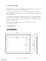
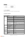
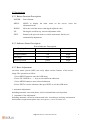
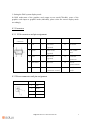
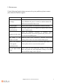
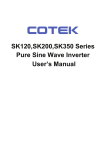
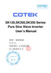
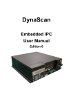
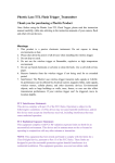
 Pole Display User Manual
CONTENT
1. Main Features …………………………………………….........…. 1
2. Appearance
-2.1 Overall appearance ………………………………...……. 2
-2.2 Interface …………………………………………………. 3
3. Attachment ……………………………………………………….. 3
4. Specifications
4.1 Tech specifications ……………………………………….
4.2 Instructions
4.2.1 Button Function Description ……………………......
4.2.2 Indicator Status Description ………………………...
4.2.3 Basic Adjustment …………………………………...
4.3 Connector
4.3.1 VGA connector and pin assignment ………………...
4.3.2 Power connector and pin assignment ………………..
3
4
4
4
4
4
5. Maintenance ……………………………………………………… 5
1. MAIN FEATURES
Pole Display Solux with overall anti-electromagnetic shield to make it looks nice and
effectively solve the electromagnetic compatibility problem.
By selecting the backlight inverter circuit, this Pole Display can not only meet the
needs of high-brightness requirements but also can ensure longer back light lamp
life and reduce cost.
Wide temperature industrial-grade display driver board used in the Pole Display make
it suit for harsh environments no matter high temperature or low temperature. What’s
more the anti- static protection circuit specifically to enhance the reliability of the monitor
and reduce maintenance costs.
This Pole Display perform gorgeous color and high fidelity to make it
outstanding for your business!
2.APPEARANCE
2.1 Overall appearance
[email protected] / www.solux-tech.com
1
2.2 Interface
3. ATTACHMENT
Display data transfer cable*1, power cable*1, extension pole (optional)
4. SPECIFICATIONS
4.1 Tech specifications
Parameter
Display area
Display diagonal size
Drive system
Chromatic number
Pixel
Pixel size
Aspect Ratio
View Angle
TFT LCD
Information
196.0(width)x147.0 (height)mm
9.7inch
a-Si TFT-LCD active matrix
Brightness
16.7M(6-bit+Hi-FRC)
1024(Horizontal)x768(Vertical)Pixel
0.192(width)x 0.192(height)mm
4:3
Horizontal:70°
Vertical:60°
Ton(white 90﹪→black 10﹪)+Toff(black
10﹪→white 90﹪)16-30ms(Typical value)
250cd/m2 (Typical value)
Horizontal Frequency
55~75KHz
Field Frequency
55~65Hz
Signal Level
Input Voltage
0.7Vp-p
DC12V
Response time
Input
Signal
Power
Supply
Working
condition
Storage
Condition
Input Current
1.5A(max)
Temperature
-20~600
Humidity
5~95%RH
Temperature
-30~700
Humidity
5~95%RH
[email protected] / www.solux-tech.com
2
4.2 Instructions
4.2.1 Button Function Description
POWER:
Power Button。
MENU:
MENU to display the main menu on the screen, select the
adjustment items.
DOWN:
Move the scroll bar down, reducing the adjusted value.
UP:
Moving the scroll bar up, increase adjustment value.
EXIT:
Return to the previous menu or exit the main menu. Hot key for
automatically adjustment.
4.2.2 Indicator Status Description
Power Indicator Description
Working Status
Indicator Color
Indicator Status
Power off
off
dark
No signal/standby
red
bright
Over range
red
bright
yellow
bright
Normal operation
4.2.3 Basic Adjustment
on-screen menu system (OSD) can easily adjust various features of the screen
image. The operations as follow:
1. Press MENU button to enter the OSD menu
2. Press UP / DOWN or + / - keys to select different submenus.
3. Press MENU button to enter selected submenus.
4. Press EXIT to exit the submenu, then press EXIT to exit the OSD menu.
1. Automatic Adjustment
Including automatic correction phase, clock, horizontal and vertical position
2. Automatic Color Adjustment
Including automatic correction contrast and color. According to working environment
and customer requirements please adjust the brightness, contrast and RGB color.
[email protected] / www.solux-tech.com
3
3. Setting the DOS system display mode
In DOS mode,most of the graphics card output as text mode(720x400), some of the
graphics card output as graphics mode (640x400), please select the correct display mode
accordingly.
4.3 Connector
4.3.1 VGA connector and pin assignment
pin
function
pin
function
pin
function
connector
1
6
2
Red circuit
11
disconnect
green
7
12
SDA(DDC
Green circuit
data)
(ground)
3
red
(ground)
VGA output
blue
8
Blue circuit
13
(ground)
4
disconnect
9
disconnect
horizontal
synchroniz
14
vertical
synchronization
5
ground
10
ground
Synchronous circuit)
15
SCL(DDC
clock)
4.3.2Power connector and pin assignment
Power connector
pin
function
1
12V
2
GND
[email protected] / www.solux-tech.com
4
5. Maintenance If the following listed solution can not solve your problem, please contact
your dealer for further support.
Phenomenon
Solution
Please check the monitor whether have connected with
power.Whether the power is turned on and the button ON /
No image
OFF has been turned off the screen
No input signal
Please check whether VGA cable have connect correctly.
Out/beyond of
synchronization
The input signal does not support the display mode, please
refer to display mode
Please try automatic
correction or
manually
adjust
Image not in the center Horizontal Position and vertical position and please refer to
on-screen menu(OSM)system
The image
is
too
bright or too dark
Please try Auto Color Correction or manually adjust RGB
setting, please refer to on-screen menu(OSM) system
When Close Windows Please try automatic correction or manually adjust Phase and
screen appears
Clock, please refer to on-screen menu system."
interference lines
Can not adjust RGB
setting
Please check the color temperature setting is in the USER
state, only when the color temperature setting is in USER
state the RGB settings can be adjusted
[email protected] / www.solux-tech.com
5