1
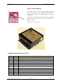
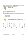
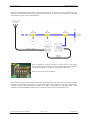
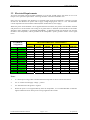
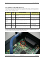
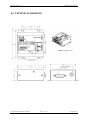
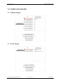
Microair Avionics Pty Ltd Airport Drive Bundaberg Queensland 4670 Australia Tel: +61 7 41 553048 Fax: +61 7 41 553049 e-mail: [email protected] Microair Avionics EC2002 Altitude Encoder About This Document This manual describes the installation of the Microair EC2002 altitude encoder. Microair has supplied additional information to enable the EC2002 to be installed with a variety of transponders. The manual is a restricted document, and may not be amended, copied, or distributed, without the written permission of Microair Avionics. © Microair Avionics Pty Ltd CURRENT REVISION STATUS Revision 1.0 01R2 01R3 01R4 01R5 01R6 Date 23/09/03 18/05/07 28/06/07 09/07/07 12/05/08 15/07/08 Change Initial Draft Specifications and calibration procedures updated Minor amendments Update Microair UAV format Warranty Statement Upgrade Updated to reflect changes in 01R7-2 version hardware and 01R7-2 software 01R7 07/09/08 Changed reference to maximum altitude to 38,000ft 01R8 24/11/08 3 view drawing updated 01R9 07/01/09 Weight data added 01R10 25/02/09 Limited Warranty Updated 01R11 24/04/09 [email protected] - email change 01R12 16/04/10 Microair altitude data format amended to add CRC EC2002 Installation Manual 01R12.doc Page 2 of 16 16th April 2010 Microair Avionics EC2002 Altitude Encoder TABLE OF CONTENTS 1.0 INTRODUCTION 4 1.1 ATSO APPROVAL 4 1.2 RTCA COMPLIANCE 4 2.0 DESCRIPTION 5 3.0 INSTALLATION 6 3.1 PHYSICAL REQUIREMENTS 6 3.2 ELECTRICAL REQUIREMENTS 8 4.0 SERIAL ALTITUDE OUTPUT 9 5.0 FIELD CALIBRATION 11 5.1 ADJUSTMENTS 12 6.0 TECHNICAL DRAWING 13 7.0 WIRING DIAGRAMS 14 7.1 GILLHAM OUTPUT 14 7.2 SERIAL OUTPUT 14 8.0 LIMITED WARRANTY 15 EC2002 Installation Manual 01R12.doc Page 3 of 16 16th April 2010 Microair Avionics EC2002 Altitude Encoder 1.0 INTRODUCTION This manual describes the performance specification, installation methods, and calibration procedures of the EC2002 Altitude Encoder. 1.1 ATSO Approval Pending. 1.2 RTCA Compliance The EC2002 hardware development is compliant to RTCA/DO-254 level C. The EC2002 software development is compliant to RTCA/DO-178B level C. The EC2002 is compliant to DO-160D for following: [(A1)(D1)X]CAB[SRU]XXXXXXABABA[UU]Z[XXXX]XXX EC2002 Installation Manual 01R12.doc Page 4 of 16 16th April 2010 Microair Avionics EC2002 Altitude Encoder 2.0 DESCRIPTION The EC2002 is housed in a 1mm black anodised case, with a mounting flange at each side. Fitted to one end of the case are a DB15 male connector for all electrical connections and a female 1/8” NPT fitting for connection to the aircraft’s static air pressure system. At the opposite end is the nameplate showing the compliance statements, the part number, serial number, and mod status. The top of the case is fitted with a label which has the pin assignments for the DB-15 connector, and clearly identifies the NPT fitting. There are two holes in the top of the case to access the HIGH and LOW keys. These keys are used in the calibration of the EC2002, and are clearly marked on the top cover label. The EC2002 is fitted with a sensitive pressure transducer to sense the air pressure present at the NPT fitting. The transducer output is “digitised” into a numerical value and outputted as an altitude via the 10 line Gillham interface and simultaneously to the serial data interface. The EC2002 will typically start outputting altitude data 10 seconds after being turned on. The maximum calibration range is between -1000 feet and +35,000 feet. The HIGH and LOW keys provide an offset to adjust the outputted altitude value up or down in 25ft steps. The EC2002 is temperature controlled to ensure the pressure transducer is at nominal temperature, in an ambient temperature range of -20 to +55 degrees C. A heater element maintains the pressure transducer core temperature within operational specification. Power consumption with the heater element off is 10mA, and a maximum of 100mA @ 14V or 200mA @ 28V with the heater element on. The heater will be fully off when ambient air temperatures are above 15 degrees C. IMPORTANT NOTE The EC2002 will cease outputting altitude data if: 1. The pressure altitude goes above 35,000 feet 2. The pressure altitude drops below -1000 feet 3. The sensor temperature is not within operational range EC2002 Installation Manual 01R12.doc Page 5 of 16 16th April 2010 Microair Avionics EC2002 Altitude Encoder 3.0 INSTALLATION Microair Avionics recommends that the EC2002 be typically positioned on the fire wall behind the instrument panel. If this position is not possible, the EC2002 can be attached to any flat surface, or purpose made bracket, and retained with 3mm (1/8”) hardware via the holes (8) in the mounting plate. The EC2002 should be supported by a minimum of two points on the mounting flanges. IMPORTANT NOTE No additional holes are to be drilled into the case for the purpose of mounting. Microair recommends that the installer should consider the fact that the encoder may have to be dismounted to allow for recalibration periodically. The retaining hardware should be easy to remove, or the HIGH and LOW key holes should be accessible in the installed position. 3.1 Physical Requirements The EC2002 may be installed in either a pressurised or non-pressurised cabin. The EC2002 should however ideally be located: In an area where the temperature can be reasonably controlled Away from cold air vents Away from heater elements or hot air vents Away from coaxial cables IMPORTANT NOTE The EC2002 may NOT be installed with the DB-15 connector and NPT fitting facing upwards, to negate the possibility of lint and dust corrupting the connections. EC2002 Installation Manual 01R12.doc Page 6 of 16 16th April 2010 Microair Avionics EC2002 Altitude Encoder Microair recommends that the EC2002 and the aircraft’s altimeter be the first two items plumbed on to the static line. This will make isolating the rest of the aircraft easy to do when the system requires a calibration check. Refer to section 5.0 for field calibration. Prior to installation, it may be necessary to remove the top cover and set the serial data output switches for the correct data format and resolution. The switch settings have no effect on the Gillham output lines. Refer to section 4.0 for format details. After installing, remove the dust plug from the NPT fitting, and connect the static hose line ensuring the NPT connector is sealed using thread tape or an appropriate sealer (not silicone). Connect the wiring harness terminated with a DB-15 from the transponder, to the DB-15 fitting adjacent to the NPT fitting on the EC2002. Ensure that the DB-15 thumbscrews are secured to the hex-nuts on the EC2002’s case. EC2002 Installation Manual 01R12.doc Page 7 of 16 16th April 2010 Microair Avionics EC2002 Altitude Encoder 3.2 Electrical Requirements All wiring associated with the EC2002 installation in an aircraft, should comply with FAA AC 43.13-1A Chapter 11 or equivalent requirements. All wiring should be a minimum 22AWG in size. Power may be supplied to the EC2002 as a switched supply from the transponder, or directly from the aircraft bus. The EC2002 can operate with a supply voltage ranging from +10V to +33V. The maximum current requirement for the EC2002 is 200mA (heater element full on, 24V Supply). Where the power for the EC2002 is to be supplied from the aircraft bus, the positive line should be switched and passed via a circuit breaker with a rating of no greater than 1 A. Both the switch and the circuit breaker should be clearly labelled as “ALTITUDE ENCODER”. A dedicated ground line should be run from the EC2002 to the transponder, and be grounded to the transponder’s power ground to ensure correct signal levels. EC2002Pin Assignment 1 2 3 4 5 6 7 8 9 10 11 12 13 14 15 D4 A1 A2 A4 B1 RS232 In RS232 Out V+ B2 B4 C1 C4 C2 V+ GND TRANSPONDER PIN ASSIGNMETS Microair T2000SFL 21 9 10 11 12 5 2 13 17 18 20 19 2 3 King KT76A Terra TRT250 Narco AT-150 Garmin GTX 320 Collins TDR-950 M K J E 5 17 16 15 7 6 8 12 3 5 6 9 12 10 7 6 A/C V+ C B D H L A/C V+ A/C Gnd A/C V+ 2 14 3 18 4 A/C V+ A/C Gnd 18 10 9 14 13 11 18 5 14 11 12 10 7 4 14 13 A/C V+ 5 4 8 9 11 A/C V+ A/C Gnd Notes 1. V+ means input voltage, either switched from the transponder or direct from the aircraft bus. 2. A/C V+ means aircraft supply voltage – positive. 3. A/C Gnd means aircraft ground – negative. 4. Where the power is not supplied directly from the transponder, it is recommended that an indicator light be installed to show when power is being supplied to the encoder. EC2002 Installation Manual 01R12.doc Page 8 of 16 16th April 2010 Microair Avionics EC2002 Altitude Encoder 4.0 SERIAL ALTITUDE OUTPUT The EC2002 will output a formatted ASCII message on an RS232 Data Interface. This message contains the current pressure altitude with fixed reference to 1013.2milli-bars or 29.92 inches mercury. All formats use 8 data bits, 1 start bit, 1 stop bit & no parity. Format Baud Rate Message Formatting Example Message (5200 feet above MSL) Garmin AT 1200bps #AL, space, +/- sign, five altitude digits, T+25, checksum, carriage return #AL +05200T+25D8[CR] Magellan 1200bps $MGL, +/- sign, five altitude digits, T+25, checksum, carriage return $MGL+05200T+250C[CR] Northstar, Garmin 2400bps ALT, space, five altitude digits, carriage return ALT 05200[CR] Trimble, Garmin 9600bps ALT, space, five altitude digits, carriage return ALT 05200[CR] Microair 9600bps STX, a=, - (if negative), five altitude digits, ETX, check sum [STX]a=05200[ETX]9B The format of the serial altitude data is determined by the position of a set of six switches inside the case. To access the switches remove the 4 case screws located at the corners of the case, and lift the top cover off the base. The switches are located near the DB15 connector (refer images). EC2002 Installation Manual 01R12.doc Page 9 of 16 16th April 2010 Microair Avionics EC2002 Altitude Encoder Move the switches with a pointer to the required positions – refer to the table below for data format settings. SW1 SW2 SW3 SW4 SW5 SW6 Garmin AT (100’ steps) ON OFF OFF OFF OFF OFF Garmin AT (25’ steps) ON OFF ON OFF OFF OFF Magellan (100’ steps) ON OFF OFF ON OFF ON Magellan (25’ steps) ON OFF ON ON OFF ON Garmin Northstar (100’ steps) ON OFF OFF ON OFF OFF Garmin Northstar (25’ steps) ON OFF ON ON OFF OFF Garmin Trimble (100’ steps) ON OFF OFF OFF ON ON Garmin Trimble (25’ steps) ON OFF ON OFF ON ON Microair (100’ steps) ON OFF OFF OFF ON OFF Microair (25’ steps) ON OFF ON OFF ON OFF Microair (10’ steps) ON ON OFF OFF ON OFF Microair (1’ steps) ON ON ON OFF ON OFF Software Controlled OFF OFF OFF OFF OFF OFF Notes: 1. The software controlled option allows the EC2002 to be configured from terminal software applications. 2. The factory default setting is “software controlled” and set to GARMIN AT output with 100’ step resolution. 3. The Gillham output will always remain at 100’ step output regardless of what serial data settings are used. 4. The Microair T2000SFL (Rev 8) will self detect any of the above protocols. Refer to the T2000SFL User Manual to select serial altitude data instead of Gillham altitude data. EC2002 Installation Manual 01R12.doc Page 10 of 16 16th April 2010 Microair Avionics EC2002 Altitude Encoder 5.0 FIELD CALIBRATION The technician can perform a full calibration check over any altitude range from -1000 feet to +38,000 feet. Where the technician is required to adjust the EC2002, refer to section 5.1. IMPORTANT NOTE To complete the calibration process of the transponder / altimeter / encoder system, refer to FAR Part 43 appendix E & F. Notes EC2002 Installation Manual 01R12.doc Page 11 of 16 1. The maximum correspondence error is 125 feet. 2. The maximum transition error is +/-75 feet. 16th April 2010 Microair Avionics EC2002 Altitude Encoder 5.1 Adjustments Step 1 Apply power to the EC2002 Encoder and allow it to stabilize for 1 minute before measurements are made. Step 2 Adjust the pressure test set altitude for +1,000ft. The corresponding EC2002 altitude should also be +1,000 feet. Slowly increase and decrease the altitude +/-100ft to determine the transition points. The EC2002 should transition down to 900 feet at 950, and transition up to 1,100 feet at 1,050. Note the transition error, which should be < 25ft. Step 3 Repeat Step 2 at an altitude of +15,000ft. Test for the transition altitudes from 14,900 to 15,000 at 14,950, and 15,000 to 15,100 at 15,050 and note the transition error. Step 4 If the average transition error from steps 2 & 3 is greater than 25ft, use an appropriate blunt tool to press either the HIGH or LOW keys to increase or decrease the altitude output. Each key press will adjust the EC2002 altitude output by 25ft up to a maximum of +/- 200ft. Errors of greater than 200ft cannot be compensated for in the field, the unit must be returned to an authorised service centre for assessment. Step 5 Test EC2002 altitude value and transition points at various test altitudes as required by specific altimeter / Encoder test schedules (eg FAR43). An Allen key or the shank end of a drill bit makes a good tool to action the HIGH and LOW keys. The EC2002 is fitted with a nylon block tool guide under the lid to ensure that the tool reaches only the keys. IMPORTANT NOTE Do NOT use any sharp pointed tool to action the HIGH or LOW keys. Damage to the keys will occur. EC2002 Installation Manual 01R12.doc Page 12 of 16 16th April 2010 Microair Avionics EC2002 Altitude Encoder 6.0 TECHNICAL DRAWING WEIGHT = 95g (3 ½ oz) EC2002 Installation Manual 01R12.doc Page 13 of 16 16th April 2010 Microair Avionics EC2002 Altitude Encoder 7.0 WIRING DIAGRAMS 7.1 Gillham Output 7.2 Serial Output EC2002 Installation Manual 01R12.doc Page 14 of 16 16th April 2010 Microair Avionics EC2002 Altitude Encoder 8.0 LIMITED WARRANTY The warranty period for any Microair Avionics manufactured article is dependant on Condition of the article at time of sale and the Purchase Date. For New Articles the warranty period commences from Date of Purchase and is valid for 2 years or the minimum period defined by applicable consumer law, whichever is the longer. In the absence of original Proof of Purchase the warranty will be valid for 2 years from Date of Factory Shipment as determined by Microair Avionics. For Factory Reconditioned Articles offered for sale, the warranty period commences from Date of Purchase and is valid for 12 months. For Factory Exchanged Articles the warranty period commences from the Date of Purchase of the original article and is valid for the remainder of the original warranty period. For Repaired Articles the warranty period commences from the date of Factory Shipment and is valid for 6 months for the original defect only. Microair Avionics will, at its sole discretion, repair or replace any components, which fail in normal use. Such repairs or replacement will be made at no charge to the customer for parts or labour. The customer shall be responsible for any transportation costs for return of this product to Microair Pty Ltd or an approved Microair Service Centre. This warranty does not cover failures due to abuse, misuse, accident, unauthorised alteration, or repairs carried out by parties other than Microair Avionics or an approved Microair Avionics Service Centre. This warranty does not cover failures where the product has not been installed or operated, in accordance with the provisions of the User and Installation manual(s). It shall be at Microair Avionics sole discretion to decide if a defect is a result of material or workmanship failure. THE WARRANTIES AND REMEDIES CONTAINED HEREIN ARE EXCLUSIVE AND IN LIEU OF ALL OTHER WARRANTIES EXPRESSED OR IMPLIED, INCLUDING ANY LIABILITY ARISING UNDER WARRANTY OF MERCHANTABILITY OR FITNESS FOR A PARTICULAR PURPOSE, STATUARY OR OTHERWISE. THIS WARRANTY GIVES YOU SPECIFIC LEGAL RIGHTS, WHICH MAY VARY FROM STATE TO STATE, AND COUNTRY TO COUNTRY. IN NO EVENT SHALL MICROAIR AVIONICS PTY LTD BE LIABLE FOR ANY INCIDENTAL, SPECIAL, INDIRECT OR CONSEQUENTIAL DAMAGES, WHETHER RESULTING FROM THE USE, MISUSE OR INABILITY TO USE THIS PRODUCT OR FROM DEFECTS IN THE PRODUCT. Microair Avionics may at it discretion, refer product returns for repair or service, to a service facility closest to you. Microair Avionics reserves the right to repair or replace the product or software or offer a full refund of the purchase price at its sole discretion. To obtain warranty service, please email or call the Microair Avionics Repair line in Australia. Domestic or International Return instructions are available on our website. Please follow these instructions carefully. Phone: Fax: Email: Website: ++ 61 7 4155 3048 ++ 61 7 4155 3049 [email protected] www.microair.com.au MAP 803 Microair Avionics Warranty Statement 01R3 EC2002 Installation Manual 01R12.doc Page 15 of 16 16th April 2010 Microair Avionics EC2002 Altitude Encoder Supplied by: EC2002 Installation Manual 01R12.doc Page 16 of 16 16th April 2010