Transcript
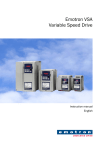
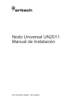
F
Model: RPK84
PCM2000
Rack Mounting Kit
F
Model: RPK84
E
E
PCM2000
Rack Mounting Kit
D
D
C
C
B
B
A
A
M
PC M
M
PC M
ZP
ZP
M
PC M
M
PC M
ZP
ZP
M
PC U
M
PC U
CP
.
...........
.
... ...........
................... .............
................ ...
................
................
...... ....
....
.
CP
M
PC
M
.
...........
.
... ...........
................... .............
................ ...
................
................
...... ....
....
.
TI
RACK MOUNTING
RACK MOUNTING
SCREWS ARE NOT
SUPPLIED
M
PC
M
TI
RACK MOUNTING
RACK MOUNTING
SCREWS ARE NOT
SUPPLIED
A 4 MODULE
ASSEMBLY
Rack
Mounting
A Typical
4-Module Assembly
A 4 MODULE
ASSEMBLY
Rack
Mounting
A Typical
4-Module Assembly
Installation
Installation
1. Position the left side of the completed PCM assembly over one of the rack mounting
adapters. Refer to the figure above and the table below to determine the correct
holes for the number of modules in the assembly.
1. Position the left side of the completed PCM assembly over one of the rack mounting
adapters. Refer to the figure above and the table below to determine the correct
holes for the number of modules in the assembly.
Total Modules
Mounting Holes
2
C&D
3
B&D
4
B&E
5
B&F
6
A&F
Total Modules
Mounting Holes
2
C&D
3
B&D
4
B&E
5
B&F
6
A&F
2. Secure the left side of the PCM system to the rack adapter using two of the truss
head sheet metal screws included with the kit.
2. Secure the left side of the PCM system to the rack adapter using two of the truss
head sheet metal screws included with the kit.
3. Secure the right side of the PCM system to the other rack adapter using the holes
for the number of modules in the assembly and the remaining two truss head sheet
metal screws.
3. Secure the right side of the PCM system to the other rack adapter using the holes
for the number of modules in the assembly and the remaining two truss head sheet
metal screws.
4. Secure the assembly to a 19" rack (rack screws not supplied).
4. Secure the assembly to a 19" rack (rack screws not supplied).
Specifications subject to change without notice.
© 2000 Bogen Communications, Inc.
Part No. 54-2032-01R3 Printed in Korea. 0203
50 Spring Street, Ramsey, New Jersey 07446
Tel. 201-934-8500, Fax: 201-934-9832
www.bogen.com
Specifications subject to change without notice.
© 2000 Bogen Communications, Inc.
Part No. 54-2032-01R3 Printed in Korea. 0203
50 Spring Street, Ramsey, New Jersey 07446
Tel. 201-934-8500, Fax: 201-934-9832
www.bogen.com