1
EC-P10
10-20 Zone Intruder Alarm System
Installation Manual
Contents
1. System Overview ........................................... 4 System Configuration ............................................................. 4 Control Panel .......................................................................... 5 Remote Keypads .................................................................... 5 EC-LED Remote Keypad ............................................................ 5 EC-LCD Remote Keypad ............................................................ 5 Expansion Modules ................................................................ 5 EC-EX10 Zone & Output Expander ........................................... 5 EC-EX10/I Zone Expander ........................................................ 5 EC-COM/IP Communication Module ...................................... 5 EC-USB-Link ............................................................................ 5 Upload/Download Software ................................................... 5 Zone Chime.............................................................................. 21 Zone Soak Test........................................................................ 21 Zone Text ................................................................................. 21 Zone Link ................................................................................. 21 2. Arming Control.................................................................. 22 Arming Timers ......................................................................... 22 Arming Modes ......................................................................... 22 Arm Options 1 .......................................................................... 22 Arm Options 2 .......................................................................... 23 Arm Keyswitch Control ............................................................ 23 Auto Arm/Disarm .................................................................... 23 3. System Configuration ....................................................... 24 System Timers ......................................................................... 24 System Counters ..................................................................... 24 2. Installation ..................................................... 6 Hardware - Volume Levels ...................................................... 25 Installation Sequence............................................................. 6 Control Panel .......................................................................... 6 Hardware - Monitoring ............................................................ 25 Mounting .................................................................................... 6 Wiring the Control Panel ........................................................... 6 Control Panel Layout ................................................................. 7 PCB Layout ................................................................................. 8 Connecting Devices to the Network ....................................... 10 Remote Keypads .................................................................. 11 PCB Layouts ............................................................................. 11 Wiring Detection Devices ..................................................... 11 Normally Closed ....................................................................... 11 Normally Open ......................................................................... 11 Single EOL - N/C ...................................................................... 12 Double EOL............................................................................... 12 Triple EOL ................................................................................. 12 Loudspeaker Connections ................................................... 12 External Sounder/Strobe Connections ................................ 13 TR .............................................................................................. 13 0V .............................................................................................. 13 +12 ........................................................................................... 13 Bell (1) ...................................................................................... 13 Strobe (2) ................................................................................. 13 Panel Outputs 1 - 5............................................................... 13 2-Wire Smoke Detectors ...................................................... 13 Telephone Line Connections................................................ 14 Commissioning ..................................................................... 14 Hardware - Output Monitoring ............................................... 25 Configuration ........................................................................... 25 Control Timers ......................................................................... 26 Banner Text ............................................................................. 26 Remote Control Labels ........................................................... 26 Voice Options ........................................................................... 26 Activate by Link Control .......................................................... 26 Voice Message Options .......................................................... 26 System Links ........................................................................... 27 4. Keypad Configuration ...................................................... 28 Keypad Options 1 .................................................................... 28 Keypad Options 2 .................................................................... 28 Keypad Sounds ....................................................................... 28 5. Expander Configuration ................................................... 29 Expander Options .................................................................... 29 Expander Sounds .................................................................... 29 Expander Outputs ................................................................... 29 Expander Output Attributes .................................................... 29 6. Panel Outputs and Devices ............................................. 30 Panel Output Type ................................................................... 30 Panel Output Attributes .......................................................... 30 Output Types ........................................................................... 30 00: Global ................................................................................ 30 Group 02: Control Timer ......................................................... 31 Group 03: Remote Control ..................................................... 31 Group 04: Link Control ........................................................... 32 Power-Up Options Menu.......................................................... 14 Group 10: Zone Count ............................................................ 32 3. Programming the Control Panel ................ 15 Group 30: Zone Alarm ............................................................ 32 Introduction........................................................................... 15 Exiting Engineer’s Program Mode ........................................ 15 Menu Navigation and Data Entry ......................................... 16 LCD Navigation ........................................................................ 16 Selection List ............................................................................ 16 Bit Toggle Selection ................................................................. 17 Number Entry ........................................................................... 18 String Edit - Number Mode ..................................................... 18 String Edit - Text Mode ............................................................ 19 1. Zone Programming ........................................................... 19 Zone Type ................................................................................. 19 Zone Wiring .............................................................................. 20 Zone Attributes ........................................................................ 20 Zone Bypass Options ............................................................... 21 2
Group 20: Zone Mimic ............................................................ 32 Group 40: Zone Tamper ......................................................... 33 Group 50: Zone Masked......................................................... 33 Group 60: Zone Fault.............................................................. 33 Group 70: Zone Bypassed ...................................................... 33 Group 80: User Access ........................................................... 33 Communication Ports ............................................................. 33 GSM & SMS Centre ................................................................. 33 IP Configuration ....................................................................... 34 7. On-board Communicator ................................................. 35 ARC 1-4: Telephone Number.................................................. 35 ARC 1-4: Account Number ...................................................... 35 ARC 1-4: Protocol .................................................................... 35 ARC 1-4: Protocol Options ...................................................... 35 ARC 1-4: Call Sequence/Attempts......................................... 35 ARC 1-4: Reported Event Groups........................................... 35 P0016-LI-02.01
ARC 1-4: Cancel on Success ................................................... 36 Chime on/off 24* .......................................................... 41 ARC 1-4: IP Address ................................................................. 36 Change Code 81* .......................................................... 41 ARC 1-4: IP Port Number ......................................................... 36 Program Mode Options: Auto Test Call Period ................................................ 36 View Zone Status Options: Auto Test Call Time ................................................... 36 Exit Menu Options: Auto Test Days .......................................................... 36 Options: PSTN Pre-Dial Number ............................................. 36 Fast Format: Reporting Channels .......................................... 36 Fast Format: Restore Channels .............................................. 37 Fast Format: Open/Close Channels ....................................... 37 Channel Type ........................................................................... 38 Channel Attributes ................................................................... 38 Speech Dialler: Telephone Numbers 1 and 2 ....................... 38 Speech Dialler: Dial Sequence ............................................... 38 Speech Dialler: Trigger Type ................................................... 38 UDL Options ............................................................................. 38 UDL Password .......................................................................... 38 UDL Ring Count ........................................................................ 39 Call-Back Number .................................................................... 39 UDL Dial Sequence .................................................................. 39 UDL Remote IP Address .......................................................... 39 UD Remote IP Port ................................................................... 39 UDL Account Number .............................................................. 39 8. System Users .................................................................... 40 User Access Code .................................................................... 40 User Type .................................................................................. 40 User Locked By ........................................................................ 40 User Name ............................................................................... 40 User Link................................................................................... 40 9. Utilities .............................................................................. 41 Time and Date.......................................................................... 41 User Menus ........................................................................... 41 Away Arm A......................................................................... 41 Stay Arm 1 S ...................................................................... 41 Stay Arm 2 2* ................................................................... 41 Stay Arm 3 3* ................................................................... 41 Walk Test 11* ................................................................. 41 Test Bell & Outputs Do Test Call 12*................................................. 41 13* ............................................................. 41 View Event Log 21* ........................................................ 41 Print Event Log 22* ........................................................ 41 Call UDL P0016-LI-02.01
91* ........................................................ 41 92* ................................................... 41 99* ................................................................ 41 Log Events ............................................................................ 42 LED Indications..................................................................... 45 Fault & Status Messages ..................................................... 45 Resetting Faults & alarms ...................................................... 45 4. Specifications .............................................. 46 EC-P10 Control Panel ........................................................... 46 Electrical .................................................................................. 46 Environmental ......................................................................... 46 Physical .................................................................................... 46 EC-LED Remote Keypad ....................................................... 46 Electrical .................................................................................. 46 Environmental ......................................................................... 46 Physical .................................................................................... 46 EC-LCD Remote Keypad ....................................................... 46 Electrical .................................................................................. 46 Environmental ......................................................................... 46 Physical .................................................................................... 46 EC-EX10/I Zone Expander ................................................... 46 Electrical .................................................................................. 46 Environmental ......................................................................... 46 Physical .................................................................................... 46 EC-EX10 Zone & Output Expander ...................................... 47 Electrical .................................................................................. 47 Environmental ......................................................................... 47 Physical .................................................................................... 47 EC-COM/IP Communication Module ................................... 47 Electrical .................................................................................. 47 Environmental ......................................................................... 47 Physical .................................................................................... 47 Standards ............................................................................. 47 Safety ....................................................................................... 47 EMC .......................................................................................... 47 Security .................................................................................... 47 Warranty ............................................................................... 47 23* ................................................................... 41 3
1. System Overview
System Configuration
4
P0016-LI-02.01
Control Panel
Expansion Modules
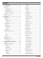
The EC-P10 control panel is an advanced intruder alarm system
with 10 on-board zones and on-board multi format communicator.
The system can be expanded to 20 zones using the 10 zone
expansion modules (EC-EX10 or EC-EX10/I). The system is ideally
suited to domestic and small commercial installations.
The following expansion modules are available:
The control panel provides a multi-channel integrated speech
dialler and voice annunciation feature. Voice messages are
recorded via a touch tone telephone or by using the Eclipse UDL
software package.
Remote arming and disarming and system control can also be
carried out by calling the protected premises with a touch-tone
telephone. On answering the incoming call you are greeted with a
voice prompted menu.
The system can be further enhanced by using the EC-COM/IP
module which provides both IP and X-10 connectivity. X-10 is a
simple home automation protocol that uses the existing mains
wiring to communicate with X-10 compatible devices via a XM10U
controller. Once the EC-COM/IP is installed, both the system and
X-10 devices can be controlled remotely using smart phone apps.
A choice of either LCD or LED remote keypads is available. Other
features include:
EC-EX10 Zone & Output Expander
The EC-EX10 is a housed zone and output expansion module that
is connected to the 4-wire control panel network. Features
include:
f
10 fully programmable zone inputs
f
10 programmable outputs (8 x 100mA; 2 x 1Amp)
f
Internal piezo sounder
f
16Ω loudspeaker connection, with programmable volume
f
Tamper protection
f
Engineer keypad port
f
Stylish housing
EC-EX10/I Zone Expander
The EC-EX10/I is a housed zone expansion module that is
connected to the 4-wire control panel network. Features include:
f
10 fully programmable zone inputs
f
10 programmable on-board zones
f
Tamper protection
f
5 programmable outputs (1Amp rated)
f
Stylish housing
f
On-board communicator/modem/speech dialler
f
Local or remote upload/download
EC-COM/IP Communication Module
f
250 event log
f
1.5 Amp switched mode power supply
f
Two communication ports for accessories etc
f
Loudspeaker output
f
Selectable battery charging rate
f
Real time clock
f
f
The EC-COM/IP is an IP based communicator and X-10 home
automation interface PCB module. Features include:
f
Ethernet connection to LAN/WAN
f
Remote access via Eclipse UDL or smart phone app
f
Alarm reporting via LAN/WAN to PC based alarm receiver
f
X-10 port for automating X-10 devices via XM10U/E
controller
Two-wire smoke detector support
f
X-10 devices controlled via the system or smart phone app
Flash upgradable
f
PCB module clips into EC-P10 control panel housing
Remote Keypads
The EC-P10 will accept up to a maximum of 4 remote keypads. All
remote keypads require a 4-wire connection to the control panel
using standard alarm cable. The following remote keypad models
are available:
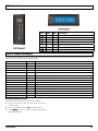
EC-LED Remote Keypad
The LED keypad features a dual 7 segment display for displaying
zone status and system fault messages. A set of dedicated
system status LEDs for AC, Ready, Armed, Trouble, Bypass, Alert
and Alarm are also provided. Other features include:
EC-USB-Link
The EC-USB-Link provides USB connectivity between the EC-P10
and the host computer. It is required when a direct connection is
required between the Eclipse UDL software package and the
control panel.
Upload/Download Software
f
4-wire connection using standard alarm cable
Eclipse UDL is a Windows® based software package that can be
used to remotely or locally program and diagnose the Eclipse
range of security systems. Features include:
f
Internal sounder
f
Simple intuitive user interface
f
Backlit keyboard
f
Local or remote via modem and IP
f
System remote control
f
Advanced system diagnostics
f
Multi language support
f
System audit trail
EC-LCD Remote Keypad
The LCD keypad features a 2 x 20 character blue display for
showing all zone status and system fault messages. A set of
dedicated system status LEDs for AC, Trouble and Alert are also
provided. Other features include:
f
4-wire connection using standard alarm cable
f
Internal sounder
f
Backlit keyboard
P0016-LI-02.01
5
2. Installation
Installation Sequence
Before attempting to install the alarm system, read this section.
Once you have an overall understanding of the installation
sequence, carefully work through each step.
1. Design the Layout
Make a rough sketch of the premises to get an idea of where all
alarm detection devices, keypads and other modules are to be
located.
2. Mounting the Control Panel
The control panel must be mounted within the protected area
close to an unswitched AC power source and the incoming
telephone line.
You must complete all wiring before connecting the battery, or
applying AC to the panel.
3. Install the Remote Keypads
Mount the remote keypads at locations that are easily accessible
during entry and exit from the protected area. Connect the remote
keypads to the control panel.
4. Zone Wiring
Install detection devices and connect to control panel or
expander.
Wiring the Control Panel
WARNING: ELECTRICITY CAN KILL
BEFORE connecting the control panel ALWAYS
disconnect the supply at the consumer unit.
If in ANY doubt consult a qualified electrician.
ONLY connect the mains supply to the mains terminal
block, NEVER connect the mains supply directly to the
PCB.
The system installation MUST be carried out in
accordance with the national safety standards, for
example EN 60950: 1992.
ALWAYS refer to National Wiring Regulations when
conducting installation.
An appropriate and readily accessible disconnection
device (e.g. an unswitched fused spur) MUST be
provided as part of the installation.
The disconnection device must NOT be fitted in a
flexible cord.
5. Other Wiring
Complete all other wiring including external/internal sounders
and telephone line connections.
Where identification of the neutral in the mains supply
is NOT possible, a two-pole disconnection device MUST
be used.
6. Apply Power to the Control Panel
Once steps 1 to 5 are completed, apply power to the control
panel. First, connect the red battery lead to the positive terminal
and the black lead to negative. Then, connect the AC.
The building mains supply MUST incorporate
appropriate short-circuit backup protection (e.g. a fuse
or circuit breaker) of High Breaking Capacity (HBC, at
least 1500A).
7. Program the System
If available use the Eclipse UDL software package to program the
system, if this is not available program this system in accordance
with the procedures in Section 3.
Use mains cable of adequate carrying capacity for the
rated current (i.e. at least 0.75mm2).
8. Testing the System
Test the system thoroughly to ensure that all features and
functions are operating as required.
Control Panel
Mounting
Mount the control panel on a flat, plumb wall using at least three
appropriate screws. The rear casing has been designed with a
central key-hole slot so that mounting is possible without
removing the Printed Circuit Board (PCB).
The angled slot in the lower corner has been provided to allow the
panel to be levelled easily. If the PCB has to be removed, carefully
pull back the two front PCB securing clips, lift the front of the PCB
and slide it downward. To replace the PCB simply reverse the
above procedure.
It is essential to ensure that none of the fixing slots or cable
entries are accessible after fixing.
Mains cabling must be secured (e.g. with a cable tie) to one of the
anchor points provided.
6
P0016-LI-02.01
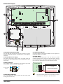
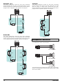
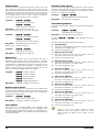
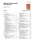
Control Panel Layout
1
5
2
3
4
1. Main Printed Circuit Board (PCB)
The main PCB that provides the terminals connection to remote
keypads and detection devices, see PCB Layout on next page for
full details.
2. Switched Mode Power Supply
The switch mode power supply module is housed under this
protected area and provides power to the main PCB via the threeway harness.
5. Communication Module
An optional Eclipse communication Module can be clipped into
the housing under the main PCB.
5. Standby Battery
The system housing will accept a 12V 7Ah battery to provide
continued operation in the event of an AC mains failure. Connect
the red battery lead to the positive terminal of the battery and
then connect the black battery lead to the negative terminal.
Control Panel
E
L
R
12V 7Ah
Sealed Lead Acid Battery
BAT
N
To Power Supply
Module
Network
D
3. Mains Connection
The AC Mains supply is connected to a 3 way Euro Type fused
terminal block, which is fitted with a 500mA fuse.
6
Fuse T500mA
4. Mains Supply Cable Entry
The mains supply cable must be routed into the control panel
housing via this cable entry.
P0016-LI-02.01
The system will only become “live” when the AC supply is
connected or the “Battery On” pins are shorted.
7
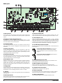
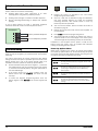
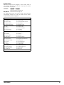
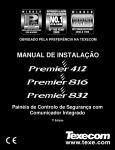
PCB Layout
18
16
17
16
16
15
14
13
1
12
2
3
4
5
6
7
1. PSU Connector
The harness from the switched mode power supply module plug
onto this connector and provides the power (13.7V) to power the
system.
2. Engineer’s Remote Keypad Connector
An engineer’s remote keypad maybe plugged onto to this
connector so that system programming and testing can be carried
out at the location of the control panel.
3. Lid Tamper Switch
This switch detects when the cover is in position and the screw is
fully secured. The tamper is designed to activate when the screw
is undone.
6
8
9
10
11
10. External Sounder 12V
These terminals provide power for external sounder units. The
output is protected by an auto resetting fuse (PTC) rated at 1.1A.
11. Panel Outputs 1 to 5
These are fully programmable high current (1 Amp), switched
negative supervised outputs. Panel outputs 1 and 2 default to bell
and strobe operation, but can be programmed for other functions
if required, see page 30 for programming details. Each output can
also be programmed for supervision monitoring, see page 25.
12. Two-Wire Smoke Detector Enable
Set this link as shown when connecting 2-wire smoke detectors to
Panel Output 5.
4. Battery Connections
A 12V rechargeable battery must be connected to these two
terminals in order to provide continuous system operation in the
event of mains failure. The battery output is protected by an auto
resetting fuse (PTC) rated at 1.6 Amp.
2-wire Smoke Detectors Enabled: Panel Output 5
must be programmed as “2-wire Smoke” (0047)
and smoke detectors must be connected as shown
page 13.
5. Network Connections
The network terminals provide connections to the remote keypads
and zone expanders. The + and – terminals provide power whilst
the R and R terminals are the data signals.
2-wire Smoke Detectors Disabled: Panel Output 5
will function as a normal output.
6. Zone Inputs 1 to 10
Detection devices such as movement sensors, vibration and door
contacts are connected to the zone input terminals. There are
several ways in which to wire a detection device (see page 11).
Each zone is fully programmable, see page 19 for information on
programming zones.
13. Communication Ports 1 and 2
Two serial communication ports 1 and 2 are provided for local
downloading and for third party devices.
7. Auxiliary 12V
These terminals provide auxiliary power for detection devices that
require 12V power, e.g., moment sensors. The auxiliary output is
protected by an auto resetting fuse (PTC) rated at 1.1 Amp).
8. Speaker
These terminals are used for driving 16Ω extension loudspeakers
(see page 12).
9. Bell Tamper Return
This terminal is connected to the tamper return connection from
an external sounder unit. If it is not required link it to 0V.
8
14. RJ11 Telephone Line Connector
An RJ11 connector is provided so that the panel can be
connected to the telephone line via a standard RJ11 patch lead.
15. Telephone Line Connections
Telephone line connections (see page 14).
16. Power/Status LED
On steady when either AC or standby battery is present. Flashes
when the on-board communicator is dialling or sending data.
17. Battery Charging Rate
The standby battery can be recharged at different rates:
P0016-LI-02.01
300mA: This is the recommended charge rate for a
7Ah standby battery. The system will fully recharge a
flat battery within 24hours.
750mA: This is the recommended charge rate for a
17Ah standby battery. The system will fully recharge
a flat battery within 24hours.
18. Battery On (Kick Start)
When powering the system from battery only, the “Battery On”
pins must be momentarily shorted together with a plain blade
screwdriver or similar to kick start the power supply into
operation.
P0016-LI-02.01
9
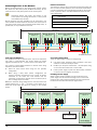
Network Connections
The network is made up of four terminals incorporating power and
data. To ensure correct operation, all four terminals on the device
must be connected to the corresponding terminals on the control
panel, or previous device. The table below shows each terminal
and its description:
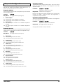
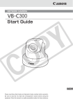
Connecting Devices to the Network
Before connecting devices to the control panel network, isolate
ALL power from the control panel (AC Mains & Battery). Do not
continue if there is still power present on the control panel.
Connecting devices with power still present on the
control panel may damage the device or control panel
and invalidate any warranty.
Remote keypads and zone expanders are all connected to the
same network terminals located at the bottom left hand corner of
the control panel and may be connected serially (daisy chain), in
parallel (star) or any combination of the two.
+
+12V Supply
-
0V Supply
R
Data Return
D
Data I/O
500 metres
Remote Keypad
Remote Keypad
Zone & Output Expander
Remote Keypad
Address = 1
Address = 2
Address = 1
Address = 3
IN
12V 0V R
D
12V 0V R
OUT
12V 0V R
D
D
12V 0V R
12V 0V R
D
D
R
D
Control Panel
Network
To additional devices
Overcoming Voltage Drop
There are several ways to overcome voltage drop:
Cable Type and Distances
For improved immunity to electrical noise, the use of screened 4
core cable is recommended. The screen should be twisted
together and wired into the (–) terminal at the control panel only.
The maximum recommended distance for devices when using
standard 7/0.2 alarm cable is:
f
250m for each branch when using the star (parallel)
configuration
f
When using a daisy chain (series) configuration the
maximum distance will depend on the number of devices
connected on the chain. The more devices that are
connected, the shorter the distance to the last device (this is
due to voltage drop in the cable)
f
Use thicker lower resistance cable. Standard 7/0.2 alarm
cable has a resistance of 8Ω per 100m
f
Double up on the power connections – this will require using
a 6 or 8-core cable rather than a 4-core cable
f
Install a power supply to power the device locally, remember
to common the two negative connections
Installing a Power Supply
When a power supply is installed, the 0V connections on the
power supply must be connected through to 0V on the control
panel and the +12V connection between the control panel and
the device must be disconnected (see figure below).
Whichever method of wiring configuration is used, ensure that the
voltage between the ‘+’ and ‘–’ terminals at each device is no
lower than 10.0V when the system is running on the standby
battery.
1km
500 metres
Remote Keypad
Remote Keypad
Remote Keypad
Remote Keypad
Address = 1
Address = 2
Address = 3
Address = 4
12V 0V R
D
12V 0V R
D
12V 0V R
12V 0V R
D
D
R
D
Control Panel
Network
Disconnect +12V
from control panel
12V 0V
Power Supply
10
P0016-LI-02.01
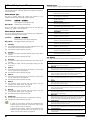
Remote Keypads
Wiring Detection Devices
PCB Layouts
The EC-P10 provides 10 zones for connecting detection devices
such as movement sensors and magnetic door contacts. Each
zone is fully programmable to allow for maximum flexibility (see
page 19 for Zone Programming details). The program options for
a zone will also determine how the zone may be wired. The
following wiring options are available:
2
1
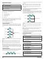
Normally Closed
This wiring configuration should be used when connecting
detection devices that only have a normally closed alarm output.
Connect the detector as shown below and ensure that the zone is
programmed for “Normally Closed” operation, see page 20.
3
Zx Com Zy
4
LED Remote Keypad
Alarm
Alarm
1 Detector
1
Alarm
2
2 Detectors
Normally Open
4
This wiring configuration should be used when connecting
detection devices that only have a normally open alarm output.
Connect the detector as shown below and ensure that the zone is
programmed for “Normally Open” operation, see page 20.
Zx Com Zy
3
LCD Remote Keypad
1. Network Connections
The remote keypad is connected to the network terminals located
at the bottom left hand side of the PCB.
2. Address Selection
Each remote keypad must be assigned a different address using
the Address selector. Move the jumper to the required position 1,
2, 3 or 4.
3. Tamper Switch
The lid tamper for each remote keypad can be enabled or
disabled if required. Please refer to page 28 for further details.
4. Piezo Sounder
The piezo sounder generates low level alarm, key press, and
warning tones. Each type of tone can be enabled or disabled for
each remote keypad, please refer to page 28 for further details.
Alarm
Alarm
1 Detector
Alarm
2 Detectors
P0016-LI-02.01
11
Single EOL - N/C
Triple EOL
This wiring configuration should be used when connecting
detection devices that only have a normally closed alarm output.
Connect the detector as shown below and ensure that the zone is
programmed for “Single EOL – N/C” operation, see page 20.
This wiring configuration should be used when connecting
detection devices that support triple EOL configuration, this will
allow the system to monitor alarm, tamper fault and mask.
Connect the detector as shown below and ensure that the zone is
programmed for “Triple EOL” operation, see page 20.
Zx Com Zy
Alarm
2K2
Alarm
Fault
4K7
Zx Com Zy
Alarm
3K3
1 Detector
Alarm
3K3
Tamper
2 Detectors
2K2
E.O.L
1 Detector
Double EOL
This wiring configuration should be used when connecting
detection devices that have a normally closed alarm and tamper
output. Connect the detector as shown below and ensure that the
zone is programmed for “Double EOL” operation, see page 20.
Zx Com Zy
Loudspeaker Connections
SPK
The EC-P10 has a loudspeaker output capable of driving one 16Ω
or two 8Ω wired in series as shown below:
Alarm
Tamper
Tamper
SPK
Alarm
4K7
4K7
16Ω Loudspeaker
8Ω Loudspeaker
2K2
E.O.L
Alarm
4K7
1 Detector
8Ω Loudspeaker
The volume level can be programmed, please refer to page 25 for
details. The loudspeaker can also be tested, please refer to page
25 for further details.
Tamper
2K2
E.O.L
2 Detectors
12
P0016-LI-02.01
External Sounder/Strobe Connections
Panel Outputs 1 - 5
The following connections are available for connection to an
external sounder/strobe unit:
The control panel has five programmable outputs, which can be
used to drive auxiliary devices such as LEDs, sounders or relays
etc. (see page 30 for details on programming outputs). Each
panel output is rated at 1 Amp and switches to 0V when active.
The figure bellow shows some wiring examples:
Tamper Return input. Connect to the tamper output on the
external sounder/strobe unit. If this input is not used it must be
linked to 0V.
0V
cathode
12V
0V supply. Connect to the 0V (-) supply on the external
sounder/strobe unit.
Control Panel
OP
TR
+12
Positive 12V supply, which is protected by an auto resetting fuse
(PTC) rated at 1.1A. Connect to the +12V (+) supply on the
external sounder/strobe unit.
Panel output 1 is pre-configured for Bell operation, i.e. it switches
to 0V when active. Connect this terminal to the bell trigger input
on the external sounder/strobe unit. The output can be inverted
for SCB operation, see page 30 for details.
LED Indicator
Control Panel
12V Relay
12V
Strobe (2)
LED
OP
Bell (1)
anode
1K
+
Panel output 2 is pre-configured for Strobe operation, i.e., it
switches to 0V when active. Connect this terminal to the strobe
input on the external sounder/strobe unit.
Control Panel
Relay Driver
External Sounder
OP
+12V Suppy
12V Buzzer
12V
2
1
Bell -ve
TR 0V 12V
Control Panel
Strobe -ve
0V
+
Tamper
Buzzer Driver
2-Wire Smoke Detectors
A maximum of 10, 12V 2-wire smoke detectors can be connected
to the control panel using panel output 5. The detectors must be
connected as shown below. The Enable 2-wire jumper link must
be set as shown and the output must be programmed for “2-wire
Smoke” (0047) operation, see page 30 for details.
A Maximum of 10 2-Wire Smoke Detectors
can be connected to panel output 5
0V
V Out
0V
V Out
E.O.L
12V
1K
5
Control Panel
V In
P0016-LI-02.01
V In
13
Telephone Line Connections
En
The control panel has an advanced on-board communicator and
modem, which can be used for the following:
f
Sending digital alarm status information to an alarm
receiving centre using industry standard protocols
f
Sending voice messages to a mobile or landline telephone
f
Remote uploading/downloading via Eclipse UDL software
package
If any of these features are used, a permanent telephone
connection should be made to the control panel as shown:
Control Panel
T1
R1
T
R
Out to premises telephone
In from telephone provider
Engineers Menu
Location:----
LED
LCD
f
Program the system as described in the next section
(Programming the Control Panel).
f
Carry out a walk test as described on page 41. Remember
that some powered detectors (e.g. PIRs and combined
technology detectors) take several minutes to warm up
before they become operational.
f
Test the internal sounder, external sounder and strobe as
described on page 41.
f
Replace the lid and secure with the lid screw supplied - do
not over-tighten.
f
Enter *99 to leave the programming menus.
f
The Service light will be flashing to indicate that action is
required. Switch on the mains supply to the control panel.
The Service light will stop flashing and stay on continuously.
Installation is now complete and the system is ready for use.
Please ensure the system users are provided with adequate
training on operating the alarm system.
Commissioning
Once ALL connections have been made to the control panel and
power is ready to be applied, you should read this section before
continuing.
The control panel leaves the factory programmed with default
settings and when the system is powered up for the first time the
default settings are in use. If the factory defaults need to be
reloaded in the future, please see “Power-up Options Menu”.
Power-Up Options Menu
When power is applied to the system, the control panel enables
the “Power-Up Options Menu” for 10 seconds. During this period
the control panel status LED flashes between red and green and
the system will accept the following commands:
Command
Description
*0#
Default Engineer Code
Entering this command will set engineer access code
back to 1234.
Connect the black battery lead to the negative (–) terminal of
the standby battery and the red battery lead to the positive
(+) terminal of the standby battery. The green power LED on
the main PCB will light.
*3#
Save as Factory Defaults
Entering this command will save the current control
panel program configuration as the NEW factory
default profile.
f
If the system enters into an alarm condition, enter the
default master user code 5678. The alarm tone will
then stop.
*6#
Set UDL Password
Entering this command will set the UDL password to
123456.
f
To access the Engineer Programming Menu, enter the
default engineer code 1234. The remote keypads will
show:
*9#
Load Factory Defaults
Entering this command will set all control panel
program configuration options to the factory default
settings.
f
14
P0016-LI-02.01
3. Programming the Control Panel
Section
Introduction
This section covers the system programming and it is important
that all engineers read this section carefully so as to familiarise
themselves with the many features and functions of the control
panel. To access the programming menu, enter the factory default
engineer code 1234. If a mistake is made whilst entering the
code, simply re-enter the code correctly.
When the system is in Engineers Mode, ALL zones and
tampers are disabled.
Each programming option is accessed by a four digit location
number followed by *. The location numbers have been grouped
together into logical sections. The programming sections are as
follows:
Section
Page
1 Zone Programming
1 Zone Types
2 Wiring
3 Zone Attributes
4 Reserved
5 Bypass Options
6 Chime Options
7 Soak Test
8 Zone Text
9 Zone Links
19
2 Arming Options
0 Full Arm Options
1 Stay Arm 1 Options
2 Stay Arm 2 Options
3 Stay Arm 3 Options
22
3 System Configuration
1 System Timers
2 System Counters
3 Hardware Options
4 Configuration
5 Control Timers
6 Banner Text
7 Voice Message Links
8 Voice Message Options
9 System Output Links
24
4 Keypad Options
11 Keypad Options 1
12 Keypad Options 2
13 Keypad Sounds
28
5 Expander Options
11 Expander Options
12 Expander Sounds
2 Expander Output Type
3 Expander Output Attributes
29
6 System Devices
1 Panel Outputs
2 Com Ports
3 GSM & SMS Centre
4 IP Configuration
P0016-LI-02.01
Page
7 On-board Communicator
0 ARC 1 - 4 Configuration
1 Options
2 Fast Format
3 Speech Dialler
4 UDL Options
35
8 Users
1 User Code
2 User Type
3 User Time Locks
4 User Name
5 User Link
40
9 Utilities
0 Set Time and Date
41
Exiting Engineer’s Program Mode
To exit the engineers programming menus and return to the
normal disarmed mode, ensure the display is prompting you to
enter a location number then enter 99*.
30
15
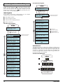
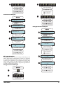
Menu Navigation and Data Entry
LCD sub menu navigation
Enter Engineers code
1234
Each programming location is accessed by entering its four digit
location number followed by *. If you don’t know the exact
location you can enter less than four digits and the panel will take
you to the first location that starts with numbers you have
entered. For example if you enter 12 the panel will take you to
location 1201 – Zone 01 Wiring Type.
Engineers Menu
Location:---A =Next(up)
S =Previous (down)
* =Select section
LCD Navigation
If the system is fitted with an LCD keypad, you can navigate
through the main menu using the following keys:
Engineers Menu: 1101
Zone Setup
A = Next program section
*
S = Previous program section
Zone 01 Type
Final Exit 1
* = Select location of displayed section
R = Back a menu level
Zone 01 Wiring
Normally Open
LCD main menu navigation
Enter Engineers code
1234
Zone 01 Attributes1
.2..5..
Engineers Menu
Location:----
A
S
A =Next(up)
S =Previous (down)
* =Select section
Engineers Menu: 1101
Zone Setup
Engineers Menu: 2001
Away/Stay Options
Engineers Menu: 3101
Global Options
Engineers Menu: 3501
Control Timers
Engineers Menu: 3601
System Text
Engineers Menu: 3701
Voice/System Links
A
S
Engineers Menu: 4111
Keypad Options
Engineers Menu: 5111
Expander Options
Engineers Menu: 6111
Panel Outputs
Engineers Menu: 7001
ARC Options
Engineers Menu: 7311
Speech Dialler
Section start location
Section description
Section start location
Section description
Zone 01 Bypass
12.....
A = Next(up)
S = Previous (down)
* = Previous location
# = Next location
R = Back a menu level
Zone 01 Chime
Off
Zone 01 On Test
No
Zone 01 Text
Front Door
Zone 01 Link
000
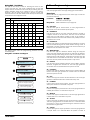
Selection List
This type of data entry is used when selecting an option from a
predefined list. Each item in the list has a number and associated
description. When using the LCD keypad for programming the
description is displayed. The LED keypad can only display the
number. The figures below show the programming procedure for
both LED and LCD remote keypads:
Selection List: LED Keypad
Enter Engineers code
????
En
Enter location No
???? e.g. 1101
1 1 0 1
Press * to display
the current value
Engineers Menu: 7400
UDL Options
1 1 0 1 =1
Engineers Menu: 8100
User Codes
Location number & current
value are displayed.
Enter item number, e.g., 04
Engineers Menu: 9001
Adjust Clock
16
P0016-LI-02.01
1 1 0 1 =4
Press * to accept
and return to step Ì
Press R to cancel
and return to step Ê
Press # to accept
and move to next location
Selection List: LCD Keypad
Enter Engineers code
????
Engineers Menu
Location:---Enter location No
???? e.g. 1101
Engineers Menu
Location:1101
Press * to display
the current value
Zone 01 Type
Final Exit 1
Press B to scroll through
list options or enter item
number, e.g., 04
Zone 01 Type
Intruder
To display the item number
press and hold any
number key.
Zone 01 Type
04
Press * to accept
and return to step Ì
Press R to cancel
and return to step Ê
Press # to accept
and move to next location.
Bit Toggle Selection
This type of data entry is used for enabling and disabling up to 8
options. Each option is represented by a number 1 to 8 and has
an associated description. When using the LCD keypad for
programming the description can be displayed by holding down
the bit option number, the LED keypad can only display the
number. The figures below show the programming procedure for
both LED and LCD remote keypads:
Bit Toggle Selection: LED Keypad
Enter Engineers code
????
En
1 3 0 1 =2 =5
Location number & current
options are displayed.
Options 2 & 5 are enabled.
Use keys 1 to 8 to toggle
options on or off, e.g, press
2 to turn option2 off.
0 = All options off.
9 = All options on.
1 3 0 1 =5
Press * to accept
and return to step Ì
Press R to cancel
and return to step Ê
Press # to accept
and move to next location
Bit Toggle Selection: LCD Keypad
Enter Engineers code
????
Engineers Menu
Location:---Enter location No
???? e.g. 1301
Engineers Menu
Location:1301
Press * to display
the current value
Zone 01 Attributes 1
.2..5..
Location number & current
options are displayed.
Options 2 & 5 are enabled.
Use keys 1 to 8 to toggle
options on or off, e.g, press
2 to turn option2 off.
0 = All options off.
9 = All options on.
Zone 01 Attributes 1
....5..
To display the option
description press and hold
the option number key.
Auto rearm
....5..
Press * to accept
and return to step Ì
Press R to cancel
and return to step Ê
Press # to accept
and move to next location.
Enter location No
???? e.g. 1301
1 3 0 1
Press * to display
the current value
P0016-LI-02.01
17
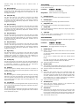
Number Entry
String Edit - Number Mode: LED Keypad
This type of data entry is used for entering numeric values, such
as timers. The figures below show the programming procedure for
both LED and LCD remote keypads:
Number Entry: LED Keypad
Enter Engineers code
????
En
Enter location No
???? e.g. 3101
3 1 0 1
Press * to display
the current value
3 1 0 1 =0
Location number & current
value are displayed (0).
Enter required value, e.g, 35.
3 1 0 1 =3 5
Press * to accept
and return to step Ì
????
En
Enter location No
???? e.g. 7011
7 0 1 1
Press * to display
the current value
7 0 1 1=
Location number & current
value are displayed (blank).
Enter required value,
e.g, 1234.
To clear value press * & R
7 0 1 1=
1 2 3 4
Press * to accept
and return to step Ì
Press R to cancel
and return to step Ê
Press R to cancel
and return to step Ê
Press # to accept
and move to next location
Press # to accept
and move to next location
Number Entry: LCD Keypad
String Edit - Number Mode: LCD Keypad
Enter Engineers code
????
Engineers Menu
Location:---Enter location No
???? e.g. 3101
Engineers Menu
Location:3101
Press * to display
the current value
System Timers
AC Fail:000
Location number & current
value are displayed (0).
Enter required value, e.g, 35.
System Timers
AC Fail:035
Press * to accept
and return to step Ì
Enter Engineers code
????
Engineers Menu
Location:---Enter location No
???? e.g. 7011
Engineers Menu
Location:7011
Press * to display
the current value
ARC 1 Account
ÿ
Location number & current
value are displayed (blank).
Enter required value,
e.g, 1234.
To clear value press * & R
ARC 1 Account
1234ÿ
Press R to cancel
and return to step Ê
Press * to accept
and return to step Ì
Press # to accept
and move to next location.
Press R to cancel
and return to step Ê
String Edit - Number Mode
This type of data entry is used for entering a long string of
numbers, such as telephone and account numbers. The figures
below show the programming procedure for both LED and LCD
remote keypads:
18
Enter Engineers code
Press # to accept
and move to next location.
P0016-LI-02.01
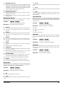
String Edit - Text Mode
This type of data entry is used for entering text such as user
names and zone text. This mode is designed only for the LCD
keypad. The text is entered in the same way as entering text on a
mobile telephone. Each key is mapped to one or more letters.
Pressing a key will select the first letter, pressing it again will
select the next etc. The table below shows the keys to use and the
characters that are assigned to them:
Key
1
Characters
1. Zone Programming
This section covers programming of the detection zones, each
zone must programmed a zone type, wiring type and attributes.
Zone Type
Each zone must be programmed to the correct type in order for
the correct response.
Locations:
1101 to 1120
Mode: Selection List (see page 16).
1
Zone 01 to 20: Zone Type.
2
A
B
C
2
a
b
c
Entry Mode:
3
D
E
F
3
d
e
F
4
G
H
I
4
g
h
i
00 Not Used
Use this zone type for unused zones, as zone programmed as
“Not Used” are not be monitored by the system.
5
J
K
L
5
j
k
l
6
M
N
O
6
m
n
o
7
P
Q
R
S
7
p
q
8
T
U
V
8
t
u
v
9
W
X
Y
Z
9
w
x
0
_
0
.
-
(
)
#
B
r
s
y
z
Clear all characters
The figures below show the programming procedure for LCD
remote keypads:
String Edit - Text Mode: LCD Keypad
Enter Engineers code
????
Engineers Menu
Location:---Enter location No
???? e.g. 1801
Engineers Menu
Location:1801
Press * to display
the current value
Zone 01 Text
ÿ
Location number & current
value are displayed (blank).
Use text editing keys
to enter text, e.g, HALL
Zone 01 Text
HALLÿ
Press * to accept
and return to step Ì
Press R to cancel
and return to step Ê
Press # to accept
and move to next location.
01 Final Exit 1
Use this zone type for the main entry/exit detector, normally a
magnetic contact on the front door. The zone can be activated
during the exit mode without causing a fault. If the system is
armed, activation of the zone will start the Entry 1 Delay timer for
the relevant arm mode.
02 Final Exit 2
Use this zone type for an alternative entry/exit detector. The zone
can be activated during the exit mode without causing a fault. If
the system is armed, activation of the zone will start the Entry 2
Delay timer for the relevant arm mode.
03 Walk Through
Use this zone type for detection devices along the entry/exit
route. This zone type will allow the user to walk past the detector
without causing a fault during the exit mode or an Intruder alarm
during the entry mode. However, if activated at any other time the
zone will cause an immediate intruder alarm. This zone type will
also start the entry mode when the system is stay armed.
04 Intruder
Use this zone type for detection devices such as PIR’s, vibration
detectors, magnetic door contacts etc. This zone type generates
an intruder alarm if activated when the system is armed.
05 Perimeter
Use this zone type for detection devices such as external PIR’s, IR
beams. This zone type generates an intruder alarm if activated
when the system is armed.
06 Fire
Use this zone type for smoke and heat detectors. This zone type
generates a distinctive fire alarm if activated at any time.
07 PA Silent
Use this zone type for panic buttons. This zone type generates a
silent panic alarm if it is activated at any time.
08 PA Audible
Use this zone type for panic buttons. This zone type generates an
audible panic alarm if it is activated at any time.
09 Medical
Use this zone type for medical alarms. This zone type generates a
medical alarm if it is activated at any time.
10 24 Hour
Use this zone type for detectors that require 24 hour monitoring.
This zone type generates an intruder alarm if it is activated when
the system is armed. If activated during the disarmed state an
internal alarm is generated.
11 Tamper
Use this zone type for tamper protection. This zone type generates
a tamper alarm if it is activated when the system is armed. If
P0016-LI-02.01
19
activated during the disarmed state an internal alarm is
generated.
12 Exit Terminator
Use this zone type for external push to set buttons. This zone type
terminates the exit delay when activated during exit mode. The
arming mode must be configured for “Exit Terminator” for this
zone type to function.
13 Away Arm Key
Use this zone type for a key switch or lock that has switch
contacts. This zone type will away arm the system when active
and disarm the system when healthy. If a “momentary” operation
is required then the “Momentary Keyswitch” attribute can be
assigned, see page 21.
14 Stay 1 Arm Key
Use this zone type for a key switch or door lock that has switch
contacts. This zone type will stay arm (1) the system when active
and disarm the system when healthy. If a “momentary” operation
is required then the “Momentary Keyswitch” attribute can be
assigned, see page 21.
15 Stay 2 Arm Key
Use this zone type for a key switch or door lock that has switch
contacts. This zone type will stay arm (2) the system when active
and disarm the system when healthy. If a “momentary” operation
is required then the “Momentary Keyswitch” attribute can be
assigned, see page 21.
16 Stay 3 Arm Key
Use this zone type for a key switch or door lock that has switch
contacts. This zone type will stay arm (3) the system when active
and disarm the system when healthy. If a “momentary” operation
is required then the “Momentary Keyswitch” attribute can be
assigned, see page 21.
17 Bypass Key
Use this zone type for a key switch or door lock that has switch
contacts. This zone type will bypass all zones with the bypass
attribute when active and reinstate them when healthy. If a
“momentary” operation is required then the “Momentary
Keyswitch” attribute can be assigned, see page 21.
18 Security Key
Use this zone type for a key switch. This zone type will disable all
remote keypads when active and reinstate them when healthy. If
a “momentary” operation is required then the “Momentary
Keyswitch” attribute can be assigned, see page 21.
19 Auxiliary
Use this zone type for auxiliary devices, which do not require an
audible alarm response. This zone type generates a silent alarm if
activated at any time.
20 Warning
Use this zone type for monitoring devices that require a warning
indication. This zone type generates a warning (low level beeps
from the keypad every 30 seconds and zone indication) if the
zone remains active for longer than the warning delay time, see
page 24 for details.
21 Log/Monitor
Use this zone type for monitoring devices that require an event log
entry. This zone type generates a log entry if activated at any time.
22 Trouble/Fault
Use this zone type for monitoring fault outputs on devices such as
remote power supplies. This zone type generates a fault condition
if it is activated at any time.
20
Zone Wiring
Each zone must be programmed to the correct wiring type in order
for the correct response.
Locations:
1201 to 1220
Entry Mode:
Mode: Selection List (see page 16).
Zone 01 to 20: Zone Wiring.
0
Normally Closed
Use this wiring type for normally closed detection devices.
1
Normally Open
Use this wiring type for normally open detection devices.
2
Single EOL - N/C
Use this wiring type for normally closed detection devices.
3
Double EOL
Use this wiring type for detection devices that require both alarm
and tamper monitoring.
4
Triple EOL
Use this wiring type for detection devices that require alarm,
tamper, fault and anti-mask monitoring.
Zone Attributes
Each zone can have one or more optional attributes programmed
to further alter its functionality.
Locations:
1301 to 1320
Zone 01 to 20: Zone Attributes.
Entry Mode:
Bit Toggle Selection (see page 17).
1
Double Knock
On: When a zone is enabled for Double Knock it will only cause
an alarm when:
(a) The zone remains active for the duration of the “Double
Knock Delay”.
(b) The zone is violated twice within the “Double Knock
Delay”.
(c) If any two zones with the “Double Knock” attribute are
activated during the “Double Knock Time Window”.
Off: The zone functions as normal.
2
Enable Comms
On: The on-board communicator will report the alarm status to
the monitoring station when the zone causes an alarm.
Off: The alarm status is not transmitted.
3
Reset
On: Zones with this attribute will not be monitored during the
detector reset period. The detector reset occurs when the
exit mode is started or when the user resets the system after
an alarm. Detection devices such as smoke detectors that
are powered from an output programmed as “Detector
Reset” should have this attribute switched on.
Off: The zone functions as normal.
4
Zone Response
On: Zones with this attribute respond at the response rate
determined by the “Zone Response Timer”.
Off: The zone functions as normal.
5
Auto Rearm
On: Zones with this attribute will only re-arm at the end of the
bell duration providing that the “Auto Re-Arm Counter” limit
has not been reached. Once this limit has been reached, the
zone will lock out and not cause any further Intruder alarms.
Off: The zone will always re-arm.
P0016-LI-02.01
6
Remote Detector Test
On: Zones with this attribute are monitored for specific activity
during the remote detector test. The detector must be
connected to the control panel using triple EOL wiring and
the detector remote test input must be connected to a panel
output programmed as “Remote Detector Test”.
Off: The zone functions as normal.
2
Tone 2
The zone generates chime tone 2 when activated in the disarmed
mode.
7
Momentary Keyswitch
On: If the zone type is a keyswitch type, the operation mode is
changed to momentary.
Off: If the zone type is a keyswitch type, the operation remains as
latching mode.
4
Voice
The zone generates a prefixed voice response (e.g. “Zone 3”) from
the control panel loudspeaker output when activated in the
disarmed mode.
Zone Bypass Options
Each zone can have one or more optional bypass attributes
programmed to control when the zone is bypassed.
Locations:
1501 to 1520
Zone 01 to 20: Zone Bypass Options.
Entry Mode:
Bit Toggle Selection (see page 17).
3
Tone 3
The zone generates chime tone 3 when activated in the disarmed
mode.
Zone Soak Test
Each zone can be put on test for a programmed soak test period.
When a zone is on test it will not cause an alarm if activated, but
the system will record the failure in the event log and indicate the
fault to the user.
Locations:
1701 to 1720
Zone 01 to 20: Zone Soak Test.
Entry Mode:
Mode: Selection List (see page 16).
1
In Stay 1
On: The zone is bypassed when Stay 1 arming mode is selected.
Off: The zone is not bypassed when Stay 1 arming mode is
selected.
0
No
The zone is not on soak test.
2
In Stay 2
On: The zone is bypassed when Stay 2 arming mode is selected.
Off: The zone is not bypassed when Stay 2 arming mode is
selected.
Zone Text
3
In Stay 3
On: The zone is bypassed when Stay 3 arming mode is selected.
Off: The zone is not bypassed when Stay 3 arming mode is
selected.
Locations:
1801 to 1820
Entry Mode:
String Edit - Text Mode (see page 19).
4
By User
On: The zone can be bypassed by the user when arming the
system.
Off: The zone cannot be bypassed by the user.
5
Auto Bypass
On: The zone is automatically bypassed at the end of exit mode if
the zone is still active.
Off: The zone is not bypassed at the end of exit mode, and the
system will fail to arm if the zone remains active.
6
Keyswitch Bypass
On: The zone is bypassed when a “Bypass Key” zone type is
active and reinstated when the “Bypass Key” is secure.
Off: The zone is not bypassed when a Bypass Key is operated.
1
Yes
The zone is on soak test.
Each zone can be assigned a 20 character label that is displayed
on LCD remote keypads when viewing the zone status and event
log.
Zone 01 to 20: Zone Text.
Zone Link
Each zone can be assigned a “Link” number, which in turn is used
to control “Link Control” output types, for details on link control,
see page 32.
Locations:
1901 to 1920
Zone 01 to 20: Zone Link.
Entry Mode:
Number Entry (see page 18).
7
Cleaner
On: The zone is bypassed when a cleaner code is entered.
Off: The zone is not bypassed when the cleaner code is entered.
Zone Chime
Each zone can have an optional chime mode programmed that
allows the panel and remote keypads to generate an audible tone
when the zone is activated in the disarmed mode.
Locations:
1601 to 1620
Zone 01 to 20: Zone Chime.
Entry Mode:
Mode: Selection List (see page 16).
0
Off
The zone will not generate a chime tone.
1
Tone 1
The zone generates chime tone 1 when activated in the disarmed
mode.
P0016-LI-02.01
21
2. Arming Control
This section covers programming of the arming modes, timers
and options that control the way the system is armed.
Arming Timers
Each arming mode has its own set of timers that are used to
control various delays during arming, disarming and in alarm.
Locations:
2001 to 2007
Away Arm: Timers 01 to 07.
2101 to 2107
Stay Arm 1: Timers 01 to 07.
2201 to 2207
Stay Arm 2: Timers 01 to 07.
2301 to 2307
Entry Mode:
2
Exit Terminator
When the exit mode is started, the system will only arm after
activation of a Final Exit 1 or Final Exit 2 zone type, followed by
the activation of an Exit terminator zone, e.g., after the front door
is opened the closed and the push to set button has been
pressed.
3
Deferred
When the exit mode is started, the system will arm after the Exit
Delay timer has expired. However, if a zone off the exit route is
activated during this period, the Exit Delay timer is suspended
whilst the zone is active.
Arm Options 1
Stay Arm 3: Timers 01 to 07.
The set of options controls how the system responds for each
arming mode.
Number Entry (see page 18).
Locations:
2041 - Away Arm: Options 1.
2141 - Stay Arm 1: Options 1.
2241 - Stay Arm 2: Options 1.
2341 - Stay Arm 3: Options 1.
Entry Mode:
Bit Toggle Selection (see page 17).
01 Exit Delay
When the Arming Mode is configured as Timed or deferred, this
timer sets the delay between the user initiating the exit procedure
and the system actually arming.
02 Entry 1 Delay
When the system is armed, activation of a “Final Exit 1” zone will
start the entry 1 delay timer, this allows the user time to access
the remote keypad and disarm the system.
03 Entry 2 Delay
When the system is armed, activation of a “Final Exit 2” zone will
start the entry 2 delay timer, this allows the user time to access
the remote keypad and disarm the system.
04 Second Entry
If at the end of normal entry (Entry 1 or 2) delay, the system has
not been disarmed, the system will start the second entry delay,
during this time the internal alarm tone will sound. If at the end of
the second entry delay the system has still not been disarmed, a
full alarm is generated.
05 Bell Delay
When an alarm is generated, this timer is used to delay the
activation of the external sounder and strobe.
06 Bell Duration
When an alarm is generated, this timer is used to control the
active duration of the external sounder and strobe.
07 Comms Delay
When an alarm is generated, this timer is used to delay the
activation of the on-board communicator.
Arming Modes
This set of options control how the system is armed for each
arming mode.
Locations:
2031 - Away Arm: Arming Mode.
2131 - Stay Arm 1: Arming Mode.
2231 - Stay Arm 2: Arming Mode.
2331 - Stay Arm 3: Arming Mode.
Entry Mode:
Bit Toggle Selection (see page 17).
0
Final Exit
When the exit mode is started, the system will only arm after the
activation of a Final Exit 1 or Final Exit 2 zone type, e.g., after the
front door is opened the closed.
22
1
Timed Exit
When the exit mode is started, the system will arm after the Exit
Delay timer has expired.
1
Arming with AC off
On: The system can be armed when the mains supply is
switched off.
Off: The system cannot be armed when the mains supply is
switched off.
2
Arming with ATS Fault
On: The system can be armed with an Alarm Transmission Fault
(telephone line fault).
Off: The system cannot be armed when the mains supply is
switched off.
3
Auto Stay Arm 1
On: The system automatically performs a Stay Arm 1, if the user
does not activate a Final Exit zone.
Off: The system will always perform an Away Arm.
4
Silent Exit
On: The exit tone remains silent during exit mode.
Off: The exit tone is generated during exit mode.
5
Local Exit Tone
On: If the exit tone is enabled, the exit tone is only generated
from the remote keypad that was used arm the system.
Off: If the exit tone is enabled, the exit tone is generated from all
devices.
6
Anti-Masking when Armed
On: Anti-Masking faults are only monitored when the system is
armed.
Off: Anti-Masking faults are monitored at all times.
7
Bell on Arm Fail
On: If the system fails to arm, the external sounder and strobe is
activated.
Off: The external sounder and strobe are not activated.
8
Pulse Strobe on Arm
On: When the system is armed successfully, the external strobe
is activated for 5 seconds.
Off: The external strobe is not activated.
P0016-LI-02.01
Arm Options 2
The set of options controls how the system responds for each
arming mode.
Locations:
Entry Mode:
2042 - Away Arm: Options 2.
2142 - Stay Arm 1: Options 2.
2242 - Stay Arm 2: Options 2.
2342 - Stay Arm 3: Options 2.
Bit Toggle Selection (see page 17).
1
Only Exit when Ready
On: The exit mode can only be started if all zones are healthy
(System Ready).
Off: The exit mode can be started even if one or more zones are
active. The active zones will be indicated on the remote
keypads and a fault tone is generated.
2
Instant Bell on ATS Fault
On: The bell delay is overridden and set to zero, when the Alarm
Transmission System (ATS/on-board communicator) fault
occurs.
Off: The bell delay remains unchanged, when an ATS fault
occurs.
3
Alarms are Engineer Reset
On: Intruder alarms require an engineer to reset the system back
to normal.
Off: Intruder alarms can be reset by users.
4
Enable Bell Squawk
On: The bell output is pulsed once for a very short period when
the system is armed and twice when disarmed.
Off: The bell output operates as normal.
5
Enable Walk Squawk
On: The bell output is pulsed once for a very short period when a
zone is activated during a walk test. This option has no
effect when enabled for Stay 1, 2 or 3, i.e., only enable this
option for away arm (location 2042).
Off: The bell output operates as normal.
6
Enable Walk Voice
On: The zone and number (e.g., “Zone 10”) is announced
through the control panel loudspeaker when a zone is
activated during a walk test. This option has no effect when
enabled for Stay 1, 2 or 3, i.e., only enable this option for
away arm (location 2042).
Off: The bell output operates as normal.
7
Chime = Link 99
On: The chime feature is automatically turned on and off by Link
Control 99.
Off: The chime feature must be manually turned on or off by the
user.
Arm Keyswitch Control
The set of options controls how the system responds when a
keyswitch zone is used for arming.
Locations:
2043 - Away Arm: Keyswitch Options.
2143 - Stay Arm 1: Keyswitch Options.
2243 - Stay Arm 2: Keyswitch Options.
2343 - Stay Arm 3: Keyswitch Options.
Entry Mode:
Bit Toggle Selection (see page 17).
2
Disabled when Armed
On: The keyswitch is disabled when armed (arm only keyswitch).
Off: The keyswitch remains enabled when the system is armed.
3
Instant Arm
On: The system is armed instantly when a keyswitch is used.
Off: The normal exit mode is used to arm the system.
Auto Arm/Disarm
This set of options controls how the system Control Timers can be
used to automatically arm/disarm the system at specific times
and on specific days of the week. Please refer to page 26 for
details on Control Timer configuration.
Locations:
2051 - Away Arm: Auto Arm/Disarm
2151 - Stay Arm 1: Auto Arm/Disarm.
2151 - Stay Arm 2: Auto Arm/Disarm.
2151 - Stay Arm 3: Auto Arm/Disarm.
Entry Mode:
Bit Toggle Selection (see page 17).
1
Arm with Control Timer 1
On: The selected mode is automatically armed by Control Timer
1.
Off: The selected mode is not armed automatically.
2
Arm with Control Timer 2
On: The selected mode is automatically armed by Control Timer
2.
Off: The selected mode is not armed automatically.
3
Arm with Control Timer 3
On: The selected mode is automatically armed by Control Timer
3.
Off: The selected mode is not armed automatically.
4
Arm with Control Timer 4
On: The selected mode is automatically armed by Control Timer
4.
Off: The selected mode is not armed automatically.
5
Disarm with Control Timer 1
On: The selected mode is automatically disarmed by Control
Timer 1.
Off: The selected mode is not disarmed automatically.
6
Disarm with Control Timer 2
On: The selected mode is automatically disarmed by Control
Timer 2.
Off: The selected mode is not disarmed automatically.
7
Disarm with Control Timer 3
On: The selected mode is automatically disarmed by Control
Timer 3.
Off: The selected mode is not disarmed automatically.
8
Disarm with Control Timer 4
On: The selected mode is automatically disarmed by Control
Timer 4.
Off: The selected mode is not disarmed automatically.
1
Silent Arm
On: The exit tone remains silent during exit mode, when a
keyswitch is used to arm the system.
Off: The exit tone is generated during exit mode, when a
keyswitch is used to arm the system.
P0016-LI-02.01
23
3. System Configuration
This section covers programming of the system timers, counters,
hardware, control timers, banner text, voice options and links.
System Timers
The system timers control global system timing and delay
operation.
Locations:
Entry Mode:
3101 - AC Fail Delay.
3102 - ATS Fault Delay.
3103 - Zone Response Time.
3104 - Abort Delay.
3105 - Battery Test Period.
3106 - Battery Test Duration.
3107 - Zone Soak Test Time.
3108 - Double Knock Delay.
3109 - Service Interval.
3110 - Confirmation Period.
3111 - Pulse 1 Time.
3112 - Pulse 2 Time.
3113 - Pulse 3 Time.
3114 - Delay 1 Time.
3115 - Delay 2 Time.
3116 - Delay 3 Time.
3117 - Warning Delay.
Number Entry (see page 18).
01 AC Fail Delay
This timer is used to delay (0-255 minutes) the audible
annunciation from the keypads and internal sounders following
an AC mains failure. Default = 30 minutes.
02 ATS Fault Delay
This timer is used to delay (0-255 minutes) the audible
annunciation from the keypads and internal sounders following a
ATS fault (telephone line fault). Default = 30 minutes
03 Zone Response Time
This timer is used to control the response (0-255 x 10ms) of
zones programmed with the “Fast Response” attribute. Default =
750 milliseconds.
04 Abort Delay
This timer is used to control abort delay period (0-255 x seconds).
When an intruder alarm is generated, this timer is started and if
the system is disarmed before the timer expires an “Alarm Abort”
event is generated. This event can be signalled to the alarm
receiving centre. Default = 180 seconds.
05 Battery Test Period
This timer is used to control frequency (0-255 hours) at which the
standby battery is load tested. Default = 24 hours.
09 Service Interval
This timer controls the frequency (0-255 weeks) in which a
“Service Required” event is generated. Default = 0 weeks.
10 Confirmation Period
This timer controls the duration (0-255 minutes) in which a
confirmed alarm event can be generated. When the system is
armed and an intruder alarm is generated (first alarm), this timer
is started. If a second, but different zone activates an intruder
alarm before the timer expires, a confirmed alarm event is
generated. Default = 45 minutes.
11 Pulse 1 Time
This timer controls the active duration (0-255 seconds) of outputs
programmed with the “Pulse 1” attribute. Default = 10 seconds.
12 Pulse 2 Time
This timer controls the active duration (0-255 seconds) of outputs
programmed with the “Pulse 2” attribute. Default = 30 seconds.
13 Pulse 3 Time
This timer controls the active duration (0-255 minutes) of outputs
programmed with both the “Pulse 1” and “Pulse 2” attributes.
Default = 10 minutes.
14 Delay 1 Time
This timer controls the switch on delay (0-255 seconds) of outputs
programmed with the “Delay 1” attribute. Default = 10 seconds.
15 Delay 2 Time
This timer controls the switch on delay (0-255 seconds) of outputs
programmed with the “Delay 2” attribute. Default = 30 seconds.
16 Delay 3 Time
This timer controls the switch on delay (0-255 minutes) of outputs
programmed with both the “Delay 1” and “Delay 2” attributes.
Default = 10 minutes.
17 Warning Delay
This timer controls the delay (0-255 seconds) in which zones
programmed as “Warning” must remain active before a warning
tone is generated. Default = 60 seconds.
System Counters
The system counters are used to limit the number of times a
function or feature can be carried out.
Locations:
3201 - Auto Rearm Counter.
3202 - Number of Remote Resets.
3203 - Count Warning.
3204 - Count Logging.
Entry Mode:
Number Entry (see page 18).
01 Auto Rearm Counter
This counter controls the number of times (0-255) a zone can
rearm during an armed period. Once a zone has reached its rearm
limit, it is locked out so that it cannot cause further alarm
activations during the same armed period. Default = 3.
06 Battery Test Duration
This timer is used to control the duration (0-255 seconds) of the
standby battery load test. Default = 10 seconds.
02 No of Remote Resets
This counter controls the number of times (0-255) the UDL
software can be used to reset the system remotely before an
engineer must attend site. Default = 0.
07 Zone Soak Test Time
This timer is used to control the duration (0-255 days) of the zone
soak test. The timer is automatically started after a zone is put on
test. Default = 14 days.
03 Count Warning
This counter controls the number of times (0-255) that a zone
must activate, before triggering the corresponding “Zone ##
Count” output. Default = 0.
08 Double Knock Delay
This timer controls the duration (0-255 seconds) of the double
knock delay. The double knock delay is used to control the
operation of zones programmed with “Double Knock” attribute,
see page 20. Default = 30 seconds.
02 Count Logging
This counter controls the number of times (0-255) that a zone
must activate, before logging a “Zone Count ##” event in the
system log. Default = 0.
24
P0016-LI-02.01
Hardware - Volume Levels
This set of options controls the volume levels for each group of
system tones and voice messages.
Locations:
Entry Mode:
3301 - Panel Speaker Volume.
3302 - Chime Volume.
3303 - Advisory Tone Volume.
3304 - Alarm Tone Volume.
Number Entry (see page 18).
4
Battery Presence
On: The standby battery is monitored for its presence.
Off: The standby battery is not monitored.
5
Mains AC
On: The mains supply is monitored for its presence.
Off: The mains supply is not monitored.
6
Telephone Line
On: The telephone line connection is monitored for faults.
Off: The telephone line connection is not monitored.
01 Panel Speaker Volume
This option controls the level (0-10) of the exit, entry, fault and
warning tones from the control panel speaker. Default = 5.
7
Bell Tamper
On: The bell tamper input is monitored for activity.
Off: The bell tamper input is not monitored.
02 Chime Volume
This option controls the level (0-10) of the chime tone from the
control panel speaker. Default = 5.
Configuration
03 Advisory Tone Volume
This option controls the level (0-10) of the advisory tones from the
control panel speaker. Default = 5.
Location:
3401
Entry Mode:
Bit Toggle Selection (see page 17).
04 Alarm Tone Volume
This option controls the level (0-10) of the alarm tones from the
control panel speaker. Default = 10.
1
Auto BST/GMT
On: The system clock is automatically put forward by one hour
on the last Sunday in March at 2.00AM and put back by one
hour on last Sunday in October at 2:00AM.
Off: The system clock remains unchanged.
Hardware - Output Monitoring
This option enables/disables fault monitoring of the control panel
outputs.
Locations:
3310
Entry Mode:
Bit Toggle Selection (see page 17).
1
Panel Output 1 (Bell)
On: The output is monitored for faults.
Off: The output is not monitored.
2
Panel Output 2 (Strobe)
On: The output is monitored for faults.
Off: The output is not monitored.
3
Panel Output 3
On: The output is monitored for faults.
Off: The output is not monitored.
4
Panel Output 4
On: The output is monitored for faults.
Off: The output is not monitored.
5
Panel Output 5
On: The output is monitored for faults.
Off: The output is not monitored.
Hardware - Monitoring
This set of options allows the monitoring of the control panel
hardware to be enabled or disabled.
Locations:
3311
Entry Mode:
Bit Toggle Selection (see page 17).
1
Panel Box Tamper
On: The box tamper is monitored for activity.
Off: The box tamper is not monitored.
This set of options allows the system operation and features to be
altered.
2
Battery Test by Control Timer 5 and Disarm
On: The battery test feature is invoked when Control Timer 5
switches on and every time the system is disarmed.
Off: The battery test feature is performed by the “Battery Test
Period” timer.
3
Reinstate Bypassed Zones on Disarm
On: Any zones that have been manually bypassed are
automatically reinstated when the system is disarmed.
Off: Bypassed zones remain bypassed after the system is
disarmed.
4
Enable EN50131-1 Requirements
On: The system operates so as to comply with requirements of
EN50131-1.
Off: The system operates as normal.
5
Disable Bell when Disarmed
On: The bell output is disabled when the system is disarmed.
Off: The bell output is enabled when the system is disarmed and
if a 24hr alarm zone is activated it will trigger the bell output.
6
Disable Communications when Disarmed
On: The control panel on-board communicator is disabled when
the system is disarmed.
Off: The on-board communicator is enabled when the system is
disarmed.
7
Tamper Alarms are Engineer Reset
On: Tamper alarms require an engineer to reset the system.
Off: The user can reset tamper alarms.
8
View Active Zones
On: Zone activity is displayed when the system is disarmed.
Off: Zone activity is not displayed.
2
Auxiliary Fuse
On: The auxiliary 12V fuse is monitored for faults.
Off: The auxiliary 12V fuse is not monitored.
3
System Voltage
On: The system voltage is monitored for faults.
Off: The system voltage is not monitored.
P0016-LI-02.01
25
Control Timers
Activate by Link Control
The EC-P10 has five programmable Control Timers, each timer
has a switch on time (On Time), switch off time (Off Time) and
days of operation for both the On and Off times. Control Timer can
be used to automatically arm the system or lock users from
accessing the system. The control timer can also be assigned a
“Link” number, which in turn is used to control “Link Control”
output types, for details on link control, see page 32.
The Link Control is the logical output trigger that causes the voice
message to be played. The system has 99 “Link Control” outputs,
which can be programmed to trigger for a combination of system
events, see “Link Control” on page 32.
Locations:
Entry Mode:
3501 to 3505
Control Timers 1 to 5: On Time.
3511 to 3515
Control Timers 1 to 5: Off Time.
Entry Mode: Number Entry (see page 18).
Enter time in 24hour format, e.g., 1715 = 05.15 PM.
Locations:
3521 to 3525
Control Timers 1 to 5: On Time Days.
3531 to 3535
Control Timers 1 to 5: Off Time Days.
Entry Mode: Bit Toggle Selection (see page 17).
Options 1 to 7 = Sunday to Saturday.
Locations:
3541 to 3545
Control Timers 1 to 5: Link.
Entry Mode:
Number Entry (see page 18).
Banner Text
This set of options allows you to customise the text that is
displayed on LCD keypads. The “Stay Arm Banners” are shown
when the system has been armed in the relevant stay mode. The
“Keypad Banner” is displayed on the top line when the system is
disarmed. The “Engineer Reset Banner” is displayed on the
bottom line when the system requires an engineer to reset the
system. The top line will always show “Call Engineer”.
Locations:
Entry Mode:
3601 - Stay Arm 1 Banner.
3602 - Stay Arm 2 Banner.
3603 - Stay Arm 3 Banner.
3604 - Keypad Banner.
3605 - Engineer Reset Banner.
String Edit - Text Mode (see page 19).
Remote Control Labels
This set of options allows you to customise the text label that is
displayed on LCD keypads for each remote control output. When
the user accesses the remote control output menu, the labels are
displayed, e.g. “Garden Lights”.
Locations:
3621 to 3625
Remote Control 1 to 5: Labels.
Entry Mode:
String Edit - Text Mode (see page 19).
Voice Options
This system has 10 programmable voice messages; each
message can be up to 16 seconds long. The messages can be
recorded using the Eclipse UDL software and uploaded into the
control panel. Alternatively voice messages can be recorded from
a telephone handset.
26
Locations:
3701 to 3710
Voice Message 01 to 10: Activated by Link.
Number Entry (see page 18).
Voice Message Options
The voice message options allow you to control how the message
is played.
Locations:
3801 to 3810
Voice Message 01 to 10: Options.
Entry Mode:
Bit Toggle Selection (see page 17).
Locations: 3801 to 3810 - Voice Messages 01 to 10
“Options”.
Data Entry Mode: Bit Toggle Selection (see page 17).
1
Keep Repeating
On: The voice message repeats continuously until the associated
“Link Control” is no longer active.
Off: The voice message plays once.
2
Repeat every 10 Seconds
On: The voice message repeats every 10 seconds until the
associated “Link Control” is no longer active.
Off: The voice message plays once.
3
Repeat every 30 Seconds
On: The voice message repeats every 30 seconds until the
associated “Link Control” is no longer active.
Off: The voice message plays once.
4
Repeat every Minute
On: The voice message repeats every minute until the
associated “Link Control” is no longer active.
Off: The voice message plays once.
5
Repeat every 5 Minutes
On: The voice message repeats every 5 minutes until the
associated “Link Control” is no longer active.
Off: The voice message plays once.
6
Repeat every 15 Minutes
On: The voice message repeats every 15 minutes until the
associated “Link Control” is no longer active.
Off: The voice message plays once.
7
Repeat every 30 Minutes
On: The voice message repeats every 30 minutes until the
associated “Link Control” is no longer active.
Off: The voice message plays once.
8
Repeat every 60 Minutes
On: The voice message repeats every 60 minutes until the
associated “Link Control” is no longer active.
Off: The voice message plays once.
Options 2 to 8 can be added together to create
combined timings, e.g., if option 3 and 4 are on the
voice message will repeat every 1 minute and 30
seconds.
P0016-LI-02.01
System Links
Each system output can be assigned a “Link” number, which in
turn is used to control the “Link Control” output types, for details
on link control, see page 32.
Locations:
3901 to 3950
System Outputs 01 to 50: Link.
Entry Mode:
Number Entry (see page 18).
The table below shows the system output types and their
corresponding number 01 to 50. For details of each system
output function, please see page 30.
System Link Types
01 = AC Fault
27 = PSTN Ringing
02 = ATS Fault
28 = Battery Fault
03 = System Open
29 = Control Panel Box Tamper
04 = System Armed
30 = Bell Tamper
05 = System Part Armed
31 = Engineer on Site
06 = System Armed/Alarm
32 = Detector Reset
07 = Bell
33 = Switched 12V
08 = Strobe
34 = System Low Volts
09 = Intruder Alarm
35 = Exit Mode
10 = Confirmed Alarm
36 = Entry Mode
11 = Alarm Abort
37 = Second Entry Mode
12 = Fire Alarm
38 = General Alarm
13 = PA Alarm
39 = Auxiliary
14 = Duress Alarm
40 = Warning
15 = 24hr Alarm
41 = Keypads Locked
16 = Medical Alarm
42 = Output Fault
17 = Tamper Alarm
43 = Engineer Reset Required
18 = Ready for Arming
44 = Device Fault
19 = Trouble
45 = Service Required
20 = Alert
46 = Cleaner Bypass
21 = Bypass
47 = 2-Wire Smoke
22 = In Walk Test
48 = 2-Wire Smoke Alarm
23 = Flash 1 Second
49 = 2-Wire Smoke Fault
24 = User Test Active
50 = Door Access
25 = PSTN Fault
51 =Alarm Test
26 = PSTN Off-Hook
52 =Panel AC On
P0016-LI-02.01
27
4. Keypad Configuration
This section covers programming of the remote keypads.
Keypad Options 1
Off: The selected keypad operation remains unchanged.
Keypad Sounds
This set of options controls how the selected keypad generates
sounds from its on-board sounder.
This first set of options controls how the selected keypad onboard keys and tamper function.
Locations:
Locations:
Entry Mode:
4111 to 4114
4131 to 4134
Keypads 1 to 4: Sounds.
Bit Toggle Selection (see page 17).
Keypads 1 to 4: Options 2.
Entry Mode:
Bit Toggle Selection (see page 17).
1
Fire Activation from keys 1 and 3
On: Pressing keys 1 and 3 on the selected keypad at the same
time will generate a fire alarm event.
Off: The selected keypad cannot generate fire alarm events.
2
Medical Activation from keys 4 and 6
On: Pressing keys 4 and 6 on the selected keypad at the same
time will generate a medical alarm event.
Off: The selected keypad cannot generate medical alarm events.
3
PA Activation from keys 7 and 9
On: Pressing keys 7 and 9 on the selected keypad at the same
time will generate a panic alarm (PA) event.
Off: The selected keypad cannot generate panic alarm events.
4
Silent Keypad PA
On: If option 3 is enabled the selected keypad will generate a
silent panic alarm event.
Off: If option 3 is enabled the selected keypad will generate an
audible panic alarm event.
5
Quick Away Arm Enabled
On: The away arm mode can be carried out from the selected
keypad by simply pressing key.
Off: The user passcode must be entered at the selected keypad
before the away arm mode can be selected.
6
Quick Stay Arm Enabled
On: The stay arm mode can be carried out from the selected
keypad by simply pressing key.
Off: The user passcode must be entered at the selected keypad
before the stay arm mode can be selected.
1
Alarm Tones
On: The selected keypad generates alarm tones.
Off: The selected keypad will not generate alarm tones.
2
Trouble Tones
On: The selected keypad generates trouble tones.
Off: The selected keypad will not generate trouble tones.
3
Chime Tones
On: The selected keypad generates chime tones.
Off: The selected keypad will not generate chime tones.
4
Entry Tones
On: The selected keypad generates entry tones.
Off: The selected keypad will not generate entry tones.
5
Exit Tones
On: The selected keypad generates exit tones.
Off: The selected keypad will not generate exit tones.
6
Key Press Tones
On: The selected keypad generates key press tones.
Off: The selected keypad generates a short click tone when keys
are pressed.
7
Advisory Tones
On: The selected keypad generates advisory tones.
Off: The selected keypad will not generate advisory tones.
8
Tamper Tones
On: The selected keypad generates tamper alarm tones.
Off: The selected keypad will not generate tamper alarm tones.
7
Quick Bypass Enabled
On: The zone bypass feature can be invoked at the selected
keypad by simply pressing key.
Off: The user passcode must be entered at the selected keypad
before the bypass feature can be selected.
8
Keypad Tamper Enabled
On: The lid tamper on the selected keypad is monitored.
Off: The lid tamper on the selected keypad is not monitored.
Keypad Options 2
This second set of options controls how the selected keypad
functions when invalid keys are pressed (code tamper).
Locations:
4121 to 4124
Keypads 1 to 4: Options 2.
Entry Mode:
Bit Toggle Selection (see page 17).
1
Enable Code Tamper
On: Entering 15 or more invalid key presses on the selected
keypad will generate a code tamper event.
Off: The selected keypad cannot generate code tamper events.
2
Lockout Keypad
On: If the “Enable Code Tamper” option is enabled for the
selected keypad, the keypad operation will be locked out for
5 minutes if a code tamper event is generated.
28
P0016-LI-02.01
5. Expander Configuration
This section covers programming of the expander module. The ECP10 will only accept one expander module (EC-EX10 or ECEX10/I). The expander MUST be set to address 1.
Expander Outputs
The EC-EX10 has 10 programmable outputs. This set of options
allows the output type (function) to be assigned to each of the
expander outputs.
Locations:
Expander 1: Output 1 to 10 Type.
Expander Options
This set of options controls how the expander tamper and internal
piezo sounder function.
Location:
5111
Entry Mode:
Bit Toggle Selection (see page 17).
1
Enable Tamper
On: The lid tamper on the expander is monitored.
Off: The lid tamper on the expander is not monitored.
2
Enable Piezo
On: The internal piezo sounder on the EC-EX10 expander is
enabled.
Off: The internal piezo sounder on the EC-EX10 expander is
disabled.
5201 to 5210
Entry Mode:
Selection List (see page 16).
Enter the two digit group number followed by the two digit type
number, e.g., 0301 = “Zone 01 Alarm”. See page 30 for a
complete list of output functions.
Expander Output Attributes
This set of options allows the output attributes to be assigned to
each of the expander outputs.
Locations:
5301 to 5310
Expander 1: Output 1 to 10 attributes.
Entry Mode:
Bit Toggle Selection (see page 17).
See page 30 for details on output attributes.
Expander Sounds
This set of options controls how the EC-EX10 expander generates
sounds from its on-board piezo sounder and loudspeaker output.
Location:
5121
Entry Mode:
Bit Toggle Selection (see page 17).
1
Alarm Tones
On: The expander generates alarm tones.
Off: The expander will not generate alarm tones.
2
Trouble Tones
On: The expander generates trouble tones.
Off: The expander will not generate trouble tones.
3
Chime Tones
On: The expander generates chime tones.
Off: The expander will not generate chime tones.
4
Entry Tones
On: The expander generates entry tones.
Off: The expander will not generate entry tones.
5
Exit Tones
On: The expander generates exit tones.
Off: The expander will not generate exit tones.
6
Key Press Tones
On: Not supported on the expander.
Off: Not supported on the expander.
7
Advisory Tones
On: The expander generates advisory tones.
Off: The expander will not generate advisory tones.
8
Tamper Tones
On: The expander generates tamper alarm tones.
Off: The expander will not generate tamper alarm tones.
P0016-LI-02.01
29
6. Panel Outputs and Devices
This section covers programming of the control panel outputs,
communication ports and other devices that maybe connected to
the control panel.
Output Types
The output types are grouped together in the following groups:
Group
Description
00
Global
Global system output function.
01
Reserved
Not available on the EC-P10.
02
Control Timer
Control Timers 1 to 5.
03
Remote Control
Remote control outputs 1 to 5.
04
Enter the two digit group number followed by the two digit type
number, e.g., 3001 = “Zone 01 Alarm”.
Link Control
Input linked logical conditioned outputs.
10
Zone Count
Zones 1 to 20 count outputs.
Panel Output Attributes
20
Zone Mimic
Zones 1 to 20 mimic outputs.
30
Zone Alarm
Zones 1 to 20 alarm outputs.
40
Zone Tamper
Zones 1 to 20 tamper alarm outputs.
50
Zone Masked
Zones 1 to 20 masked outputs.
60
Zone Fault
Zones 1 to 20 fault outputs.
70
Zone Bypassed
Zones 1 to 20 bypassed outputs.
80
User Access
Users 00 to 10 access outputs.
Panel Output Type
This set of options allows the output type (function) to be
assigned to the control panel high current outputs.
Locations:
6111 to 6115
Panel Outputs 1 to 5: Output Type.
Entry Mode:
Selection List (see page 16).
This set of options allows the output attributes to be assigned to
the control panel high current outputs.
Locations:
6121 to 6125
Panel Outputs 1 to 5: Output Attributes.
Entry Mode:
Bit Toggle Selection (see page 17).
1
Latching
On: The selected output latches on when triggered and is only
cleared when the user resets the system.
Off: The selected output responds normally.
2
Inverted
On: The selected output is inverted, off when active and on when
inactive.
Off: The selected output responds normally.
3
User Test
On: The selected output is activated when the user output test is
selected.
Off: The selected output remains unchanged during the user
output test.
4
Pulse 1
On: The selected output activates for the duration of the “Pulse
1 Time” system timer, see page 24.
Off: The selected output responds normally.
5
Pulse 2
On: The selected output activates for the duration of the “Pulse
2 Time” system timer, see page 24.
Off: The selected output responds normally.
6
Delay 1
On: The selected output activates after the delay set by the
“Delay 1 Time” system timer, see page 24.
Off: The selected output responds normally.
7
Delay 2
On: The selected output activates after the delay set by the
“Delay 2 Time” system timer, see page 24.
Off: The selected output responds normally.
8
Armed Only
On: The selected output only activates if the system is armed.
Off: The selected output responds normally.
If “Pulse 1” and “Pulse 2” options are enabled then the
selected output activates for the duration of the “Pulse
3 Time” system timer, see page 24.
If “Delay 1” and “Delay 2” options are enabled then the
selected output activates after the delay set by the
“Delay 3 Time” system timer, see page 24.
30
00: Global
The table below list the output function available in this group:
No
Type & Description
00
Not Used
This output type does not activate.
01
AC Fault
This output type activates when the mains supply has been
removed for the duration of the AC Fail timer.
02
ATS Fault
This output type activates when the on-board communicator
detects a phone line fault (Alarm Transmission Fault).
03
Unset
This output type activates when the system is in the disarmed
state.
04
Armed
This output type activates when the system is armed in any of
the armed modes (Away or Stay)
05
Part Armed
This output type activates when the system is armed in any of
the Stay armed modes.
06
Armed/Alarm
This output type activates when the system is armed and pulses
when an alarm is generated.
07
Bell Active
This output type activates when an alarm is generated (it may be
delayed if the bell delay time is greater than zero). The duration
of this output type is controlled by the “Bell Duration” timer.
08
Strobe Active
This output type activates when an alarm is generated and
deactivates when the system is reset
.09
Alarm
This output type activates when an intruder alarm is generated.
10
Confirmed Alarm
This output type activates when two different zones cause an
intruder alarm.
P0016-LI-02.01
No
Type & Description
No
Type & Description
11
Alarm Abort
This output type activates when the user disarms the system
after an alarm and within the “Abort Delay” period.
35
In Exit
This output type activates when the system is in exit mode.
36
12
Fire Alarm
This output type activates when a fire alarm is generated.
In Entry
This output type activates when the system is in entry mode.
37
13
PA Alarm
This output type activates when a panic alarm is generated.
In Second Entry
This output type activates when the system is in second entry
mode.
14
Duress Alarm
This output type activates when a duress alarm is generated.
38
In Alarm
This output type activates when any alarm is generated.
15
24hr Alarm
This output type activates when a 24hr alarm is generated.
39
Auxiliary Alarm
This output type activates when an auxiliary alarm is generated.
16
Medical Alarm
This output type activates when a medical alarm is generated.
40
Warning Alarm
This output type activates when a warning alarm is generated.
17
Tamper Alarm
This output type activates when a tamper alarm is generated.
41
Keypads Locked
This output type activates when a security key is active.
18
Ready
This output type activates when the system is ready for arming,
i.e. all zones are healthy.
42
Output Fault
This output type activates when a fault is detected on one of the
monitored control panel outputs.
19
Trouble
This output type activates when a trouble alarm is generated.
43
20
Alert
This output type activates when an alert event is generated and
deactivates when the user has acknowledged the alert.
Call Engineer
This output type activates when the system requires an engineer
access code in order to reset the system.
44
Device Fault
This output type activates when a device fault is detected.
45
Service Required
This output type activates when the service timer expires.
46
Cleaner Bypassed
This output type activates when a “Cleaner Bypass” is invoked.
47
2-Wire Smoke
This output type is specifically designed for use with “Panel
Output 5”, when connecting 2-Wire Smoke Sensors.
48
2-Wire Smoke Alarm
This output type activates when a 2-Wire smoke alarm is
generated.
49
2-Wire Smoke Fault
This output type activates when a 2-Wire smoke fault is
generated.
50
Door Access
This output type activates for 30 seconds when any valid user
code is entered.
51
Alarm Test
This output type activates when the user select the alarm
sounder test.
52
Panel AC On
This output type activates when the mains supply is present.
21
Zone Bypass
This output type activates when one or more zones are
bypassed.
22
In Walk Test
This output type activates when the user walk test mode is
selected.
23
24
25
26
27
28
Flash 1 Second
This output type continually pulses on and off at a rate of 1
second.
User Test Active
This output type activates when the user test mode is selected in
the “Bell Test” menu.
PSTN Fault
This output type activates when a fault is detected on the PSTN
connected to the control panel.
PSTN Off Hook
This output type activates when an off-hook condition is
detected on the PSTN connected to the control panel.
PSTN Ringing
This output type activates when ringing is detected on the PSTN
connected to the control panel.
Battery Fault
This output type activates when a fault is detected with the
control panel standby battery.
29
Box Tamper Fault
This output type activates when the control panel box tamper is
open.
30
Bell Tamper Fault
This output type activates when the control panel bell tamper is
open.
31
Engineer on Site
This output type activates when the engineer is logged on.
32
Detector Reset
This output type is normally active and is used for powering
devices that require their power supply to be removed in order to
reset them. The output deactivates for 5 seconds at the start of
exit mode and when the system is reset.
33
Detector Latch
This output type is used to latch the alarm condition on
detection devices that have a latch input.
34
System Low Volts
This output type activates when a low voltage fault is detected
with the control panel standby battery.
P0016-LI-02.01
Group 02: Control Timer
The EC-P10 has 5 control timers each timer can be assigned to
an output:
No
Type & Description
01
Control Timer 1
This output type activates when Control Timer 1 is on and
deactivates when Control Timer 1 is off.
0205
Control Timer 2 - 5
As Control Timer 1.
Group 03: Remote Control
There are 5 remote controlled outputs, which can be assigned to
an output:
No
Type & Description
01
Remote Control 1
This output type is switched on and off via the UDL software,
smart phone app and via a touch tone telephone.
0205
Remote Control 2 - 5
As Remote Control 1.
31
Group 04: Link Control
There are 99 Link controlled outputs, which can be assigned to an
output:
The three switches represent the link inputs and are programmed
as follows:
Location 1904: Zone 04 Link = 102 (Link Control 02 “AND”).
No
Type & Description
Location 1905: Zone 05 Link = 102 (Link Control 02 “AND”).
01
Link Control 01
This output type is controlled by a combination of linked inputs.
Location 3904: System Armed Link = 102 (Link Control 02
“AND”).
0299
Link Control 02 - 99
As Link Control 01.
As the figure above shows, the Link Control 02 will be active (logic
1) only when ALL of the input links are closed (active).
To create a link controlled output you must assign link inputs to
the Link Control. The available inputs are:
f
Zone Links
f
Control Timer Links
f
Voice Message Links
f
System Links
f
User Link
Link Control Example 3
In this example we will setup “Link Control 03” so that it activates
when zone 10 “AND” Control Timer 1 is on “OR” when the system
is in exit mode “OR” when an intruder alarm occurs. The figure
below show the logic diagram for this:
Logic “1”
The inputs can be assigned to the Link Control to perform either a
logical “OR” function or a logical “AND” function. The logic
function is controlled by the link input number:
Logic “1”
001 - 099: Logical “OR” Link inputs.
Logic “1”
101 - 199: Logical “AND” Link inputs.
Link Control Example 1
In the first example we will setup “Link Control 01” so that it
activates when zone 1 “OR” zone 2 “OR” zone 3 is active “OR”
user 02 is entered. The figure below show the logic diagram for
this:
Logic “1”
Logic “1”
The four switches represent the link inputs and programmed as
follows:
Location 1910: Zone 10 Link = 103 (Link Control 03 “AND”).
Location 3541: Control Timer 1 Link = 103 (Link Control 03
“AND”).
As the figure above shows the Link Control 03 will be active (logic
1) only when link input 1 and 2 are closed (active) or when either
link inputs 3 and 4 are closed (active).
Link Control 01
Group 10: Zone Count
The zone activity count threshold of each zone can be assigned to
an output:
Location 1902: Zone 02 Link = 001 (Link Control 01 “OR”).
Location 1903: Zone 03 Link = 001 (Link Control 01 “OR”).
Location 8502: User 02 Link = 001 (Link Control 01 “OR”).
As the figure above shows the Link Control 01 will be active (logic
1) when any of the input links are closed (active). Now that Link
Control 01 is configured it can be assigned to a panel output or
voice message trigger.
Link Control Example 2
In this example we will setup “Link Control 02” so that it activates
when zone 4 “AND” zone 5 are active “AND” when the system is
armed. The figure below shows the logic diagram for this:
32
Í
Ë
Location 1901: Zone 01 Link = 001 (Link Control 01 “OR”).
Ê
Link Control 03
Location 3909: System Intruder Alarm Link = 003 (Link
Control 03 “OR”).
The four switches represent the link inputs and programmed as
follows:
Logic “1”
Ì
Location 3935: System Exit Link = 003 (Link Control 03 “OR”).
Í
Logic “1”
Ë
Ê
Ì
Logic “1”
Ê
Ë
Ì
Link Control 02
No
Type & Description
01
Zone 01 Count
This output type activates when zone 01 activity count reaches
the threshold set by the “Zone Warning” counter. See page 24.
0220
Zone 02 - 20 Count
As Zone 01 Count.
Group 20: Zone Mimic
The mimic condition of each zone can be assigned to an output:
No
Type & Description
01
Zone 01 Mimic
This output type activates when zone 01 is active and
deactivates when zone 01 is healthy.
0220
Zone 02 - 20 Mimic
As Zone 01 Mimic.
Group 30: Zone Alarm
The alarm condition of each zone can be assigned to an output:
No
Type & Description
01
Zone 01 Alarm
This output type activates when zone 01 generates an alarm and
deactivates when the alarm is reset.
P0016-LI-02.01
No
Type & Description
0220
Zone 02 - 20 Alarm
As Zone 01 Alarm.
Group 40: Zone Tamper
The tamper condition of each zone can be assigned to an output:
No
Type & Description
01
Zone 01 Tamper
This output type activates when zone 01 generates a tamper
alarm and deactivates when the alarm is reset.
0220
Zone 02 - 20 Tamper
As Zone 01 Tamper.
Group 50: Zone Masked
The mask condition of each zone can be assigned to an output:
No
Type & Description
01
Zone 01 Masked
This output type activates when zone 01 generates a mask fault
and deactivates when the fault is cleared and reset.
0220
Zone 02 - 20 Masked
As Zone 01 Masked.
Group 60: Zone Fault
The fault condition of each zone can be assigned to an output:
No
Type & Description
01
Zone 01 Fault
This output type activates when zone 01 generates a fault and
deactivates when the fault is cleared and reset.
0220
Zone 02 - 20 Fault
As Zone 01 Fault.
Group 70: Zone Bypassed
The bypass condition of each zone can be assigned to an output:
No
Type & Description
01
Zone 01 Bypassed
This output type activates when zone 01 is bypassed and
deactivates when the zone is reinstated.
0220
Zone 02 - 20 Bypassed
As Zone 01 Bypassed.
Group 80: User Access
The system access of each user can be assigned to an output:
1
Printer
This mode configures the selected communication port for printer
operation. Use this mode when using a terminal program via the
USB-Link to capture the printer output from the control panel.
2
3rd Party Module
This mode configures the selected communication port for a 3rd
Party Module operation. Use this mode when connecting a
supported 3rd party communication module to the control panel.
3
Communication Module
This mode configures the selected communication port for
Communication Module operation. Use this mode when
connecting any Eclipse communication module to the control
panel.
4
Contact ID
This mode configures the selected communication port for
Contact ID operation. In this mode the Contact ID in ASCII format
is sent to the port.
5
Debug USB-Link
This mode configures the selected communication port for data
debug operation. Use this mode when using a terminal program
via the USB-Link to capture the debug data from the control
panel.
GSM & SMS Centre
These options allow the GSM and SMS Centre to be configured.
Locations:
6301 - GPRS APN Name
6302 - GPRS APN User
6303 - GPRS APN Password
6304 - SIM Pin
6302 - SIM Credit Code
6311 - SMS Service Centre
Entry Mode:
String Edit - Number Mode (see page 18).
GPRS APN Name
The Access Point Name (APN) used by the GSM network operator
for IP packet data communication.
GPRS APN User
The APN user name used to log into the APN.
GPRS APN Password
The APN password name used to log into the APN.
Listed below are the GPRS setting used by the major UK GSM
network operators:
No
Type & Description
Operator
APN
User
Password
00
User 00 Access
This output type activates for 30 seconds after user 00 has
entered their access code.
Vodafone
internet
web
web
Orange
Orangeinternet
*
*
0110
User 01 - 10 Access
As User 00 Access.
O2
Mobile.o2.co.uk
web
web
T-Mobile
General.t-mobile.uk
*
*
Three
3internet
*
*
Communication Ports
These two options allow the operating mode for the two on-board
communication ports to be configured.
Locations:
Entry Mode:
6201 - Com Port 1: Mode.
6202 - Com Port 2: Mode.
Selection List (see page 16).
0
UDL USB-Link
This mode configures the selected communication port for UDL
USB-Link operation. The USB-Link should be connected to the
computer and the other end should be connected to the selected
control panel communication port.
P0016-LI-02.01
* = Leave blank.
SIM Pin
If the SIM is protected by a PIN, then the number must be entered
in this location in order for correct operation.
SIM Credit Code
If the GSM network operator supports credit balance via USSD,
then enter the USSD code, e.g., *123#.
33
SMS Centre Number
The system can send SMS messages to mobile telephones via the
standard PSTN telephone network. To achieve this, it uses the
ETSI ES 201 912 protocol 1. This protocol is not supported world
wide so please check with your telephone provider. Listed below
are the SMS Centre numbers for supported countries and
operators:
Country
Operator
SMS Centre Number
UK
BT
17094009
Ireland
Eirecom
17409900
Germany
T-Com
0193010
Belgium
Belgacom
14974800
France
France Telecom
0809101000
Switzerland
Swisscom
0622100000
Netherlands
KPN Telecom
0673644444
South Africa
Telkom
1091969
Caller Line Identity must be enabled in order for the SMS Centre
to accept the message.
IP Configuration
These options allow the IP details to be configured and are
required when using the EC-COM/IP module.
Locations:
6401 - IP Address
6402 - Subnet Mask
6403 - Gateway Address
6404 - Port Number
Entry Mode:
String Edit - Number Mode (see page 18).
IP Address
A valid IP address must be assigned to the module. It must be
entered in dot-decimal notation, e.g. “192.168.0.58”. Enter B3
to insert a “.”.
Subnet Mask
The subnet mask used on the network must be assigned to the
module. It must be entered in dot-decimal notation, e.g.
“255.255.255.0”. Enter B3 to insert a “.”.
Gateway Address
The gateway address (normally the ADSL router) used on the
network must be assigned to the module. It must be entered in
dot-decimal notation, e.g. “192.168.0.1”. Enter B3 to insert a
“.”.
Port Number
A valid port number must be assigned to the module. It must be
entered as a decimal number, e.g. “8888”.
34
P0016-LI-02.01
7. On-board Communicator
This section covers programming of the on-board communicator.
ARC 1-4: Telephone Number
This set of options allows the telephone number to be
programmed for each ARC.
Locations:
7001 to 7004
ARC 1 to 4: Telephone Number.
Entry Mode:
String Edit - Number Mode (see page 18).
Whilst programming telephone numbers, addition characters can
be inserted to perform the following:
1
Switch to Next ARC on failed Attempt
On: The on-board communicator switches to the next ARC in the
sequence, if the current ARC attempt fails.
Off: The on-board communicator continues dialling the selected
ARC until all its attempts have been used.
2
Use PSTN Pre-Dial
On: The on-board communicator dials the “PSTN Pre-Dial
Number” before dialling the ARC telephone number. This is
normally required when using an internal telephone system.
See “PSTN Pre-Dial Number” on page 36.
Off: The on-board communicator only dials the ARC telephone
number.
ARC 1-4: Call Sequence/Attempts
B1: Insert a “P” for a 1 second pause.
This set of options allows the call sequence to be programmed for
each ARC.
B2: Insert a “F” to force blind dialling (no dial-tone detection).
Locations:
7041 to 7044
Entry Mode:
String Edit - Number Mode (see page 18).
ARC 1-4: Account Number
This set of options allows the account number to be programmed
for each ARC.
Locations:
7011 to 7014
ARC 1 to 4: Account Number.
Entry Mode:
String Edit - Number Mode (see page 18).
ARC 1 to 4: Call Sequence/Attempts.
The call sequence is entered as a string of digits; each number
indicates the calling method:
1= PSTN (On-board Communicator)
2 = GSM Module
ARC 1-4: Protocol
3 = IP Module
This set of options allows the protocol type to be programmed for
each ARC.
The call attempts are controlled by how many digits are entered.
Here are some typical examples:
Locations:
“111” = Attempt to call the selected ARC three times using the
PSTN.
7021 to 7024
ARC 1 to 4: Protocol.
Entry Mode:
Selection List (see page 16).
“1212” = Attempt to call the selected ARC four times alternating
between PSTN and GSM.
0
Disabled
The selected ARC is disabled.
“123” = Attempt to call the selected ARC three times using PSTN,
then GSM and finally IP.
1
Contact ID
The selected ARC is configured for Contact ID protocol. When
triggered, the on-board communicator will dial the telephone
number and attempt to communicate with the alarm receiver
using Contact ID protocol.
“31” = Attempt to call the selected ARC twice, first using IP then
PSTN.
2
Fast Format
The selected ARC is configured for Fast Format protocol. When
triggered, the on-board communicator will dial the telephone
number and attempt to communicate with the alarm receiver
using standard Fast Format protocol. The control panel supports
16 Fast Format channels, see “Fast Format” on page 36.
3
Voice Format
The selected ARC is configured for Voice protocol. When triggered,
the on-board communicator will dial the telephone number and
play a fixed voice message relating to alarm event.
4
SMS Text
The selected ARC is configured for SMS protocol. When triggered,
the on-board communicator will dial the SMS Centre and send a
SMS text message to the telephone number programmed in the
ARC. See page 33 for programming the SMS Centre number.
ARC 1-4: Protocol Options
This set of options allows the protocol options to be programmed
for each ARC.
Locations:
7031 to 7034
ARC 1 to 4: Protocol Options.
Entry Mode:
P0016-LI-02.01
Bit Toggle Selection (see page 17).
ARC 1-4: Reported Event Groups
This set of options allows you to control which group of events
that are reported for each ARC.
Locations:
7051 to 7054
ARC 1 to 4: Reported Event Groups.
Entry Mode:
Bit Toggle Selection (see page 17).
1
Alarms
On: The selected ARC reports events that are assigned in the
alarm group.
Off: The selected ARC does not report alarm events.
2
Tampers
On: The selected ARC reports events that are assigned in the
tamper group.
Off: The selected ARC does not report tamper events.
3
Faults
On: The selected ARC reports events that are assigned in the
fault group.
Off: The selected ARC does not report fault events.
4
Open/Close
On: The selected ARC reports events that are assigned in the
open/close group.
Off: The selected ARC does not report open/close events.
35
5
Test/Misc.
On: The selected ARC reports events that are assigned in the
test/misc. group.
Off: The selected ARC does not report test/misc. events.
6
Restore
On: The selected ARC reports events that are assigned in the
restore group.
Off: The selected ARC does not report restore events.
7
Custom
On: The selected ARC reports events that are assigned in the
custom group.
Off: The selected ARC does not report custom events.
ARC 1-4: Cancel on Success
This set of options allows you to control communication sequence
for each ARC. When the on-board communicator is triggered by an
event it will call the ARC using the settings defined in ARC 1. If the
communication attempt is successful, this option can be used to
either cancel attempts for the remaining available ARC’s or move
on and call the next available ARC.
Locations:
7061 to 7064
ARC 1 to 4: Cancel on Success.
Entry Mode:
Bit Toggle Selection (see page 17).
1
Stop ARC 1
On: The selected ARC will cancel further attempts to ARC 1 after
a successful communication.
Off: The selected ARC will move on to next ARC after a successful
communication.
2
Stop ARC 2
On: The selected ARC will cancel further attempts to ARC 2 after
a successful communication.
Off: The selected ARC will move on to next ARC after a successful
communication.
3
Stop ARC 3
On: The selected ARC will cancel further attempts to ARC 3 after
a successful communication.
Off: The selected ARC will move on to next ARC after a successful
communication.
4
Stop ARC 4
On: The selected ARC will cancel further attempts to ARC 4 after
a successful communication.
Off: The selected ARC will move on to next ARC after a successful
communication.
ARC 1-4: IP Address
This option allows an IP address to be programmed for each ARC.
Locations:
7081 to 7084
ARC 1 to 4: IP Address.
Entry Mode:
String Edit - Number Mode (see page 18).
Whilst programming IP address, addition characters can be
inserted:
B3: Insert a “.”.
ARC 1-4: IP Port Number
This option allows an IP port number to be programmed for each
ARC.
Locations:
7091 to 7094
Options: Auto Test Call Period
The on-board communicator can be programmed to send a test
call event to the ARC. This option controls the period in hours in
which a test call is sent. The test call timer is reset every time a
system event is successfully communicated, therefore a test call
will only be sent once the timer reaches zero.
Location:
7101
Entry Mode:
Number Entry (see page 18).
Options: Auto Test Call Time
This option allows you to program a time at which the on-board
communicator sends a test call.
Location:
7102
Entry Mode:
Number Entry (see page 18).
The time must be entered in a 24hr format, e.g., 2100 = 9:00PM.
To disable this feature program the time as 0000.
Options: Auto Test Days
This option allows you to select which days of the week the onboard communicator sends a test call.
Location:
7103
Entry Mode: Bit Toggle Selection (see page 17).
Options 1 to 7 = Sunday to Saturday.
Options: PSTN Pre-Dial Number
This option allows a PSTN pre-dial number (up to 3 digits) to be
programmed. Most internal telephone systems require a digit to
be dialled before an outside line and dial tone is made available.
If this feature is required, make sure that the “Use PSTN Pre-Dial”
option is enabled for the required ARC, see “Protocol Options” on
page 35.
Location:
7104
Entry Mode:
String Edit - Number Mode (see page 18).
Fast Format: Reporting Channels
When the ARC protocol is programmed as Fast Format, the
channels that are used for reporting must be enabled or disabled.
Locations:
7201 - Reporting Channels 1 – 8.
7241 - Reporting Channels 9 – 16.
Entry Mode:
Bit Toggle Selection (see page 17).
1
Report Channel 1/9
On: For location 7201 channel 1 is enabled, for location 7241
channel 9 is enabled.
Off: For location 7201 channel 1 is disabled, for location 7241
channel 9 is disabled.
2
Report Channel 2/10
On: For location 7201 channel 2 is enabled, for location 7241
channel 10 is enabled.
Off: For location 7201 channel 2 is disabled, for location 7241
channel 10 is disabled.
3
Report Channel 3/11
On: For location 7201 channel 3 is enabled, for location 7241
channel 11 is enabled.
Off: For location 7201 channel 3 is disabled, for location 7241
channel 11 is disabled.
ARC 1 to 4: IP Port Number.
Entry Mode:
36
String Edit - Number Mode (see page 18).
P0016-LI-02.01
4
Report Channel 4/12
On: For location 7201 channel 4 is enabled, for location 7241
channel 12 is enabled.
Off: For location 7201 channel 4 is disabled, for location 7241
channel 12 is disabled.
7
Restore Channel 7/15
On: For location 7202 channel 7 is enabled, for location 7242
channel 15 is enabled.
Off: For location 7202 channel 7 is disabled, for location 7242
channel 15 is disabled.
5
Report Channel 5/13
On: For location 7201 channel 5 is enabled, for location 7241
channel 13 is enabled.
Off: For location 7201 channel 5 is disabled, for location 7241
channel 13 is disabled.
8
Restore Channel 8/16
On: For location 7202 channel 8 is enabled, for location 7242
channel 16 is enabled.
Off: For location 7202 channel 8 is disabled, for location 7242
channel 16 is disabled.
6
Report Channel 6/14
On: For location 7201 channel 6 is enabled, for location 7241
channel 14 is enabled.
Off: For location 7201 channel 6 is disabled, for location 7241
channel 14 is disabled.
Fast Format: Open/Close Channels
7
Report Channel 7/15
On: For location 7201 channel 7 is enabled, for location 7241
channel 15 is enabled.
Off: For location 7201 channel 7 is disabled, for location 7241
channel 15 is disabled.
8
Report Channel 8/16
On: For location 7201 channel 8 is enabled, for location 7241
channel 16 is enabled.
Off: For location 7201 channel 8 is disabled, for location 7241
channel 16 is disabled.
Fast Format: Restore Channels
When the ARC protocol is programmed as Fast Format, the
channels that report a restore event can be enabled or disabled.
Locations:
7202 - Restore Channels 1 – 8.
7242 - Restore Channels 9 – 16.
Entry Mode:
Bit Toggle Selection (see page 17).
1
Restore Channel 1/9
On: For location 7202 channel 1 is enabled, for location 7242
channel 9 is enabled.
Off: For location 7202 channel 1 is disabled, for location 7242
channel 9 is disabled.
2
Restore Channel 2/10
On: For location 7202 channel 2 is enabled, for location 7242
channel 10 is enabled.
Off: For location 7202 channel 2 is disabled, for location 7242
channel 10 is disabled.
3
Restore Channel 3/11
On: For location 7202 channel 3 is enabled, for location 7242
channel 11 is enabled.
Off: For location 7202 channel 3 is disabled, for location 7242
channel 11 is disabled.
4
Restore Channel 4/12
On: For location 7202 channel 4 is enabled, for location 7242
channel 12 is enabled.
Off: For location 7202 channel 4 is disabled, for location 7242
channel 12 is disabled.
5
Restore Channel 5/13
On: For location 7202 channel 5 is enabled, for location 7242
channel 13 is enabled.
Off: For location 7202 channel 5 is disabled, for location 7242
channel 13 is disabled.
6
Restore Channel 6/14
On: For location 7202 channel 6 is enabled, for location 7242
channel 14 is enabled.
Off: For location 7202 channel 6 is disabled, for location 7242
channel 14 is disabled.
P0016-LI-02.01
When the ARC protocol is programmed as Fast Format, the
channels that report an Open/Close event can be enabled or
disabled.
Locations:
7203 - Open/Close Channels 1 – 8.
7243 - Open/Close Channels 9 – 16.
Entry Mode:
Bit Toggle Selection (see page 17).
1
Open/Close Channel 1/9
On: For location 7203 channel 1 is enabled, for location 7243
channel 9 is enabled.
Off: For location 7203 channel 1 is disabled, for location 7243
channel 9 is disabled.
2
Open/Close Channel 2/10
On: For location 7203 channel 2 is enabled, for location 7243
channel 10 is enabled.
Off: For location 7203 channel 2 is disabled, for location 7243
channel 10 is disabled.
3
Open/Close Channel 3/11
On: For location 7203 channel 3 is enabled, for location 7243
channel 11 is enabled.
Off: For location 7203 channel 3 is disabled, for location 7243
channel 11 is disabled.
4
Open/Close Channel 4/12
On: For location 7203 channel 4 is enabled, for location 7243
channel 12 is enabled.
Off: For location 7203 channel 4 is disabled, for location 7243
channel 12 is disabled.
5
Open/Close Channel 5/13
On: For location 7203 channel 5 is enabled, for location 7243
channel 13 is enabled.
Off: For location 7203 channel 5 is disabled, for location 7243
channel 13 is disabled.
6
Open/Close Channel 6/14
On: For location 7203 channel 6 is enabled, for location 7243
channel 14 is enabled.
Off: For location 7203 channel 6 is disabled, for location 7243
channel 14 is disabled.
7
Open/Close Channel 7/15
On: For location 7203 channel 7 is enabled, for location 7243
channel 15 is enabled.
Off: For location 7203 channel 7 is disabled, for location 7243
channel 15 is disabled.
8
Open/Close Channel 8/16
On: For location 7203 channel 8 is enabled, for location 7243
channel 16 is enabled.
Off: For location 7203 channel 8 is disabled, for location 7243
channel 16 is disabled.
37
Channel Type
When the ARC protocol is programmed as Fast Format, the
channel type must be allocated to a system output type.
“1122” = Dial four times, first to telephone no 1 then telephone
number 2.
7211 to 7218
“1212” = Dial four times alternating between telephone number
1 and 2.
Channels 1 to 8: Channel Type.
Speech Dialler: Trigger Type
7251 to 7258
Please refer to page 30 for a complete list of output types.
Each speech dialler channel can be triggered from any of the
system output types, for example channel 1 could be
programmed to “Intruder Alarm” whilst channel 2 could be
programmed to “Fire Alarm”. Please refer to page 30 for a
complete list of output types and their corresponding type
number.
Channel Attributes
Locations:
7341 to 7344
This set of options allows the output attributes to be assigned to
the Fast Format channels.
Entry Mode:
Selection List (see page 16).
Locations:
Channels 9 to 16: Channel Type.
Entry Mode:
Locations:
Selection List (see page 16).
7221 to 7228
Channels 1 to 8: Channel Attributes.
7261 to 7268
Channels 9 to 16: Channel Attributes.
Entry Mode:
Channels 1 to 4: Trigger Type.
Bit Toggle Selection (see page 17).
UDL Options
The set of options controls how the upload/download computer
interacts with the control panel.
Location:
7400
Entry Mode:
Bit Toggle Selection (see page 17).
Please refer to page 30 for a complete list of output attributes.
Speech Dialler: Telephone Numbers 1 and 2
The on-board communicator also features a 4 channel speech
dialler which can be used to call landline or mobile telephones to
play a recorded voice message. Each channel can have two
telephone numbers assigned. When the channel is triggered the
on-board communicator will dial the number specified by the dial
sequence and play the voice message associated with the
channel for up to 1 minute. Pressing the [#] key on the telephone
handset acknowledges the call and stops the dial sequence,
pressing any other key also acknowledges the call, but the dial
sequence will continues with next number.
The speech messages are recorded using the Eclipse UDL
software package or a touch-tone telephone. The touch-tone
method is covered in the “EC-P10 User Manual”.
Locations:
7311 to 7314
Channels 1 to 4: Telephone Number 1.
7321 to 7324
Channels 1 to 4: Telephone Number 2.
Entry Mode:
String Edit - Number Mode (see page 18).
Whilst programming telephone numbers, addition characters can
be inserted to perform the following:
B1: Insert a “P” for a 1 second pause.
B2: Insert a “F” to force blind dialling (no dial-tone detection).
Speech Dialler: Dial Sequence
This set of options allows the dial sequence to be programmed for
each speech dialler channel.
Locations:
7331 to 7334
Channels 1 to 4: Dial Sequence.
Entry Mode:
String Edit - Number Mode (see page 18).
1
2 Call Answer Phone Defeat
On: Incoming calls re answered when:
a) The remote UDL computer calls in and allows the panel to
detect one or more rings.
b) The remote UDL computer ends the call.
c) The control panel answers the call immediately if the
remote UDL computer calls again within 60 seconds.
Off: Incoming calls are answered after the “Ring Count”
threshold is reached.
2
Auto Call-Back
On: After the remote UDL computer establishes a connection,
the control panel ends the call and automatically calls the
UDL computer.
Off: Call-Back only occurs if the remote UDL computer requests
it.
3
User Call-Back
On: Remote UDL access can only be established if the user
initiates from their end.
Off: Remote UDL access is enabled at all times.
4
Disable UDL when Armed
On: Remote UDL access is disabled when the system is armed.
Off: Remote UDL access is enabled at all times.
5
Disable Online Keypad
On: Remote UDL online keypad operation is disabled.
Off: Remote UDL online keypad operation is enabled.
UDL Password
The UDL password provides communication security with the
remote UDL computer. The UDL password in the control panel
must match the UDL password configured in the Eclipse UDL
software package in order to establish a communication link.
Location:
7401
Entry Mode:
Number Mode (see page 18).
The call sequence is entered as a string of digits; each number
indicates the calling method:
1: Dial Using Telephone No 1.
2: Dial Using Telephone No 2.
The call attempts are controlled by how many digits are entered.
Here are some typical examples:
38
The UDL password can be reset to a default setting of
123456 by entering *6# within 10 seconds of
powering up the system.
P0016-LI-02.01
UDL Ring Count
This counter controls how the on-board communicator takes to
answer an incoming call.
Location:
7402
Entry Mode:
Number Mode (see page 18).
Call-Back Number
When using the call back feature of the Eclipse UDL software, the
telephone number of remote UDL computer’s modem must be
configured using this option.
Location:
7403
Entry Mode:
String Edit - Number Mode (see page 18).
UDL Dial Sequence
This set of options allows the dial sequence to be programmed
when using the call-back feature.
Location:
7404
Entry Mode:
String Edit - Number Mode (see page 18).
1: PSTN (On-board Communicator)
2: SM Module
3: IP Module
The call attempts are controlled by how many digits are entered.
Here are some typical examples:
“111” = Attempt to call-back the remote UDL computer three
times using only PSTN.
“1212” = Attempt to call-back the remote UDL computer four
times alternating between PSTN and GSM.
“123” = Attempt to call-back the remote UDL computer three
times using PSTN, then GSM and finally IP.
UDL Remote IP Address
This is the IP Address of the remote UDL computer.
Location:
7405
Entry Mode:
String Edit - Number Mode (see page 18).
UD Remote IP Port
This is the IP port number of the remote UDL computer.
Location:
7406
Entry Mode:
String Edit - Number Mode (see page 18).
UDL Account Number
This is the account number used by the Eclipse UDL database.
The Eclipse UDL software will automatically assign this when you
create a new account. However, the account number can be
manually entered if required.
Location:
7407
Entry Mode:
String Edit - Number Mode (see page 18).
P0016-LI-02.01
39
8. System Users
This section covers programming of the system users.
The EC-P10 has a total of 11 users:
User 00 is the “Engineer” which has a default code of 1234.
User 01 is the “Master” user which has a default code of 5678.
Users 02 to 10 can be programmed to any user type and default
to “Not in Use”.
User Access Code
Each user must be assigned an access code in order to operate
the system; access codes may be 4, 5 or 6 digits in length. This
option allows each user to be assigned an access code.
Locations:
8100 to 8110
Users 00 to 10: Access Code.
Entry Mode:
String Edit - Number Mode (see page 18).
8
Duress
The selected user is a Duress user and operates the same as a
standard user, however, on entering the access code a silent
duress alarm is generated and if programmed, the event is
signalled to alarm receiving centre.
9
Access Control
The selected user is an Access Control user and on entering the
access code the relevant “User Access” and “Door Access” output
is activated.
User Locked By
The user access can be locked out by the use of a “Link
Controlled” output (see page 32). The “Link Control” output can
be configured to switch on by various link input conditions, e.g.,
“Link Control 01” could be programmed to operate when Control
Timer 2 is active. This means that the user access code is
disabled when the selected “Link Control” output is on and can be
used for locking out selected users for particular conditions, e.g.
you may want to prevent a user from accessing the system over
the weekend.
User Type
Locations:
The user type defines the level access the user has in order to
operate the system. This option allows the selected user type to
be assigned. User 00 and User 01 types cannot be changed.
Entry Mode:
Locations:
8200 to 8210
User Name
Users 00 to 10: User Type.
Each user can be assigned a 8 character label that is displayed
on LCD remote keypads when viewing the system event log.
Entry Mode:
Selection List (see page 16).
0
Not in Use
The selected user is not in use.
1
Engineer
The selected user is an engineer and can access all options within
the engineer’s program menu.
2
Technician
The selected user is a Technician and can access all options
except the on-board communication options within the engineer’s
program menu.
3
Master
The selected user is a Master user and can access all options
within the user menu and program new users.
8300 to 8310
Users 00 to 10: User Locked By.
Number Entry (see page 18).
Locations:
8400 to 8410
Entry Mode:
String Edit - Text Mode (see page 18).
Users 00 to 10: User Name.
User Link
Each user can be assigned a “Link” number, which in turn is used
to control “Link Control” output types, for details on link control,
see page 32.
Locations:
8500 to 8510
Users 00 to 10: User Link.
Entry Mode:
Number Entry (see page 18).
4
Manager
The selected user is a Manager user and can access all options
within the user menu.
5
Standard
The selected user is a Standard user and can access the following
options from the user menu: “Away Arm”, “Stay Arm 1/2/3”, “Do
walk Test” and “Change Code”.
6
Cleaner
The selected user is a Cleaner and can access the following
options from the user menu: “Away Arm” and “Stay Arm 1/2/3”.
The cleaner code can only disarm the system if the cleaner code
was used to arm the system. If the system was armed by another
user type and a cleaner code is entered whilst the system is
armed or during the entry procedure, the zones that have the
“Cleaner” attribute are bypassed and the entry procedure is
cancelled. When the cleaner is ready to leave the premises,
entering their code will start the exit procedure and at the end of
the exit procedure the “Cleaner” zones are reinstated.
7
Arm Only
The selected user is an Arm Only user and can only access the
arming options within the user menu.
40
P0016-LI-02.01
Stay Arm 3
9. Utilities
This section covers the programming of the system utilities.
Time and Date
The system has a real time clock that must be programmed so
that the time and date is recorded correctly in the system event
log. The time and date is also displayed on the bottom line of the
LCD keypad. If the system looses all power, the time and date is
maintained for approximately 2 days.
Locations:
Entry Mode:
9001 - Hours.
9002 - Minutes.
9003 - Seconds.
9004 - Day.
9005 - Month.
9006 - Year.
1
2
3
4
The engineer can access the user menus without exiting the
engineer’s program mode by entering 91*. The table below
shows the user menu options and the command number used to
access them.
Reset
System Tests
Event Log & UDL
Users
Command
Function
A
S/1
2
3
Away Arm
R
Reset alarm or fault
11
12
13
21
22
23
24
81
Walk Test
91
92
99
Menus
Stay Arm 2
Stay Arm 3
13*
Selecting this option will cause the on-board communicator to
send a test call to the alarm receiving centre.
View Event Log
Print Event Log
21*
22*
Selecting this option causes the contents of the event log to be
sent to the printer. Press R to exit this option.
Test Bell & Outputs
Do Test Call
Either Com1 or Com2 must be configured for “Printer”
mode in order to use this feature.
View Log
Print Log
Call UDL
Call UDL
23*
Selecting this option will cause the on-board communicator to call
the remote computer modem, so that a remote link can be
established.
Chime on/off
Change code
Program Mode
The remote computer must be setup so that it is ready
to receive the call. Only select this option when
instructed to do so by the remote computer operator.
View Zone Status
Exit Menu
A
S
2*
Selecting this option will cause the system to start the exit mode
and attempt to stay arm (2) the system. To cancel or disarm
simply enter a valid user code.
P0016-LI-02.01
Do Test Call
Go backward.
Go forward.
Press R to exit this option.
Selecting this option will cause the system to start the exit mode
and attempt to stay arm (1) the system. To cancel or disarm
simply enter a valid user code.
Stay Arm 2
Bell Output
Strobe Output
User Test Outputs
Alarm Sounder
*
#
Stay Arm 1
Selecting this option will cause the system to start the exit mode
and attempt to away arm the system. To cancel or disarm simply
enter a valid user code.
Stay Arm 1
12*
Selecting this option allows the event log to be viewed. The
following keys are used when navigating through the log:
When using the LCD keypad the menu options and their
command numbers are scrolled on the bottom line of
the LCD. If the * key is pressed, the menu option that
is currently being displayed is selected.
Away Arm
11*
Selecting this option allows the detection zones to be tested
without causing an alarm. As each zone is activated, the keypad
generates an acknowledgment tone and the zone number is
added to the list of tested zones. The tested zones are scrolled on
the keypad display. When you have finished testing the zones,
press R to exit this option.
Selecting this option allows the bell, strobe and any outputs that
have the “User Test” attribute to be switched on and off. After
selecting this command keys 1 to 4 toggle on and off the
following options. When finished, press R to exit this option:
User Menus
Arming
Walk Test
Test Bell & Outputs
Number Entry (see page 18).
Group
3*
Selecting this option will cause the system to start the exit mode
and attempt to stay arm (3) the system. To cancel or disarm
simply enter a valid user code.
Chime on/off
24*
Selecting this option will globally turn chime on or off.
Change Code
81*
Selecting this option allows you to change your own access code.
After selecting this option enter the new access code (4 - 6 digits)
followed by *.
Program Mode
91*
Selecting this option takes you back to the normal engineer’s
program mode.
View Zone Status
92*
Selecting this option either from engineer’s mode or the user
menu allows you view the status/count of each zone.
Exit Menu
99*
Selecting this option returns the system to the normal disarmed
state.
41
Log Events
LCD
LED
Description
+1/2!"/)/*GG
IA ??
Intruder alarm activated by zone ??.
+1/2!"/"01,/"GG
IR ??
Intruder zone ?? restore.
"/&*"1"/)/*GG
PeA ??
Perimeter alarm activated by zone ??.
"/&*"1"/"01,/"GG
PeR ??
Perimeter zone ?? restore.
:</)/*GG
24HrA ??
24 hour alarm activated by zone ??.
:</"01,/"GG
24HrR ??
24 hour zone ?? restore.
+1/6)/*GG
EA ??
Entry alarm activated by zone ??.
+1/6"01,/"GG
ER ??
Entry zone ?? restore.
/+&+$)/*GG
WA ??
Warning alarm activated by zone ??.
/+&+$"01,/"GG
WR ??
Warning zone ?? restore.
"!& ))/*GG
DA ??
Medical alarm activated by zone ??.
"!& )"01,/"GG
DR ??
Medical zone ?? restore.
&/")/*GG
FA ??
Fire alarm activated by zone ??.
&/""01,/"GG
FR ??
Fire zone ?? restore.
)/*GG
PA ??
Panic alarm activated by zone ??.
"01,/"GG
PR ??
Panic alarm zone ?? restore.
&)"+1)/*GG
PSA ??
Silent panic alarm activated by zone ??.
&)"+1"01,/"GG
PSR ??
Silent panic alarm ?? restore.
25)/*GG
AuA ??
Auxiliary alarm activated by zone ??.
25"01,/"GG
AuR ??
Auxiliary zone ?? restore.
,+&1,/)/*GG
MA ??
Monitor alarm activated by zone ??.
,+&1,/"01,/"GG
MR ??
Monitor zone ?? restore.
,+"GG6-00"!
By ??
Zone ?? bypassed.
,+"GG+6-00"!
UBy ??
Zone ?? unbypassed.
*-"/GG)/*
TA ??
Tamper alarm activated by zone ??.
*-"/GG"01,/"
TR ??
Tamper zone ?? restore.
,+"GG2)1)/*
FltA ??
Fault alarm activated by zone ??.
,+"GG2)1"01,/" FltR ??
Fault on zone ?? has restored.
,+"GG0()/*
MA ??
Mask alarm activated by zone ??.
,+"GG0("01,/"
MR ??
Mask alarm on zone ?? has restored.
,41Y)/*GG
LB ??
Low battery alarm from wireless device on zone ??.
,41Y"01,/"GG
LR ??
Low battery alarm on zone ?? has restored.
6-00 1&3"GG
ByA ??
Group bypass activated by zone ??.
6-00"01,/"GG
ByR ??
Group bypass by zone ?? has restored.
"604&1 % 1&3"GG
SA ??
Keyswitch connected to zone ?? is active.
"604&1 %"01,/"GG
SR ??
Keyswitch connected to zone ?? has restored.
)/* 1&3"
AA
Intruder Alarm is active.
"))0 1&3"
BA
Bell output is active.
"X/*, (,21
RL
Re-arm lockout has occurred and no more alarm can be generated for the armed period.
,+#&/*"!)/*
CA
Confirmed alarm generated (two different zones activated).
"*,1"
RA ??
Remote access via PC number ??.
0"/GG
Ur ??
User access by user ??.
2/"00GG
Dr ??
Duress alarm by user ??.
0"/$GG
UT ??
User ?? proximity tag access.
0"/GG, (,21
UL ??
User ?? has been locked out from using the system.
0"/$GG, (,21
TL ??
User ?? proximity tag has been locked out from using the system.
,!"*-"/G
CT ?
Code tamper (invalid code) generated at keypad ?.
5&11/1"!GG
ESU ??
Exit mode started by user ??.
5&11/1"!&*"/G
EST ??
Exit mode started by control timer ?.
42
"00GG
P0016-LI-02.01
LCD
LED
Description
5&11/1"!,+"GG
ESC ??
Exit mode started by zone ??.
5&11,--"!
ES
Exit mode stopped.
5&1&)"!QGG
EF ??
Exit mode failed by zone ??.
+1/61/1"!GG
EN ??
Entry mode stared by zone ??.
+1/6&*",21
ET
Entry timeout alarm.
601"*/*"!
SA
System armed.
601"*&0/*"!
SD
System disarmed.
16/*"!QG
S ?
Stay armed #? (? = 1, 2 or 3).
/*&)"!QG
AF ?
Arming failed.
/*"!&1%2)1
AU
The system was armed with an Alarm Transmission System (ATS) fault.
21,/*"!
AA
The system was automatically armed.
21,&0/*"!
AD
The system was automatically disarmed.
"*,1"/*"!
RA
The system was automatically armed remotely.
"*,1"&0/*"!
RD
The system was automatically disarmed remotely.
601"*,4"/-
SU
The system was powered up.
&)"!
ACOff
The mains ac supply has been switched off.
"01,/"
ACOn
The mains ac supply has been restored.
11"/62)1QG
BF
Battery fault #? (1: Presence Fail; 2: Load Test Fail).
11"/6"01,/"
BR
Battery fault restored.
,411"/6)/*
LB
The system standby battery voltage is low (The system is running on battery only).
&*"Z1"%+$"!
TD
The system time and date has been changed.
+$&+""/,+0&1"
ENON
The engineer access code has been entered.
+$&+""/,##0&1"
ENOF
The engineer has logged off.
"))20")/*
BFAL
The bell fuse has gone open circuit (electronic fuse).
"))20""01,/"
BFAR
The bell fuse has restored.
2520")/*
AFAL
The auxiliary 12V fuse has gone open circuit (electronic fuse).
2520""01,/"
AFAR
The auxiliary 12V fuse has restored.
11"/620")/*
BFAL ?
The battery fuse has gone open circuit (electronic fuse).
11"/620""01,/"
BFAR
The battery fuse has restored.
,5*-"/)/*
BTAL
The control panel box tamper has been activated.
,5*-"/"01,/"
BTAR
The control panel box tamper has restored.
"6-!G*-"/
RTAL ?
Keypad ? box tamper has been activated.
"6-!G*-"01
RTAR ?
Keypad ? box tamper has restored.
"3& "GG,01
RL ?
Device ?? on network lost.
"3& "GG,2+!
RF ?
Device ?? on network found.
)(1"011/1"!
TS
User walk test mode started.
)(1"01+!"!
TE
User walk test mode ended.
"))"011/1"!
BTS
User bell test started.
"))"01+!"!
BTE
User bell test ended.
21,"01))
ATC
An automatic test call was sent to the Alarm Receiving Centre (ARC).
+2)"01))
TC
A manual (user) test call was sent to the Alarm Receiving Centre (ARC).
&*"/G+
CT ? ON
Control Timer ? is on.
&*"/G##
CT ? OFF
Control Timer ? is off.
,+""01GG60
TS ??
Zone soak test has started and will run for ?? days.
,+"GG"01&)
TF ??
Zone ?? has failed whilst on test.
&/01+, (GG
FN ??
First activation from zone ??. The zone has the “Double Knock” attribute.
)/*,/1"!
AA
The user has disarmed the system within the abort delay period.
"))*-"/)/*
BTAL
The bell tamper alarm has been activated.
"))*-"/"01,/"
BTAR
The bell tamper has restored.
2)1
ATSF
The Alarm Transmission System (ATS) has detected a fault with the telephone line.
"01,/"!
ATSR
The ATS Fault has restored.
P0016-LI-02.01
43
LCD
LED
Description
"6-!G
RP ? A
A panic alarm was generated at keypad ? by pressing keys 7 and 9.
"6-!&/"G
RF ? A
A fire alarm was generated at keypad ? by pressing keys 1 and 3.
"6-!"!& )G
RD ? A
A medical alarm was generated at keypad ? by pressing keys 4 and 6.
21-21G2)1
OPF ?
The control panel has detected a fault on panel output ?.
21-21G"01,/"
OPR ?
The fault on panel output ? has restored.
)"+"/+X&1"GG
CLOS
Cleaner user number ?? is on-site (Cleaner zones are bypassed).
)"+"/##X&1"GG
CLoS
Cleaner user number ?? is off-site (Cleaner zones are un-bypassed).
,*,!2)")/*
C?A
The communication module has been disconnected/lost from com port ?
,*,!2)""01,/"
C?R
The communication module has been connected/found from com port ?
,+"GG,2+1)/*
??CA
Zone ?? has reached the “Count Logging” threshold.
44
P0016-LI-02.01
LED Indications
The figure bellow shows the LED indicators for both the LED and LCD remote keypads:
Icon
Name
LED
Description
Power
Green
Mains AC power is present.
Ready
Green
The system is ready for arming.
Armed
Green
The system is armed (Away or Stay).
Fault
Yellow
The system has one or more faults.
Bypass
Yellow
One or more zones are bypassed.
Alert
Red
One or more faults/alarms require attention.
Alarm
Red
One or more alarms have occurred.
Fault & Status Messages
Faults and status messages may be indicated during the disarmed mode or after the user disarms the system. The table below shows the
message for both the LED and LCD remote keypads:
LCD
LED
Description
*&+0,##
AC
Mains AC power is off.
11"/62)1
BF
The standby battery in the control panel has a fault.
%,+"&+"2)1
LF
The on-board communicator has detected a fault with the telephone line.
+")*-"/
PT
The box tamper on the control panel has activated.
"))*-"/
BT
The bell tamper on the control panel has activated.
))+$&+""/
CE
Call engineer to reset the system.
"/3& "".2&/"!
CR
The service timer has expired and the installation company should be contacted.
:X&/"*,(")/*
SA
One or more 2-wire smoke detectors have activated a fire alarm.
:X&/"*,("2)1
SF
One or more 2-wire smoke detectors have a fault.
"6-!G,01
R?
Keypad ? is no longer reporting to the control panel.
"6-!G*-"/
T?
The box tamper on keypad ? has activated.
5-+!"/9,01
E1
Expander 1 is no longer reporting to the control panel.
5-+!"/9*-"/
t1
The box tamper on expander 1 has activated.
21-21G2)1
O?
Output ? on the control panel has a fault.
,+"GGB)/*"!
??
Alarm activated on zone ??.
Resetting Faults & alarms
If a fault or alarm has occurred it can be reset as follows:
1.
Enter a valid access code, this will silence the alarm or
cancel the alert.
2.
Enter a valid access and press R to reset the system.
3.
Enter *99 to exit the menu. If the fault is still present it
will still be indicated.
P0016-LI-02.01
45
4. Specifications
EC-P10 Control Panel
EC-LED Remote Keypad
Electrical
Electrical
Supply Voltage:
Rated PSU Output:
Ripple:
Current:
Voltage:
Current:
230VaC.
1.5A.
<5%.
<100mA quiescent.
<150mA in alarm.
Standby Battery:
12.0V SLA, 7Ah.
Recharge Time:
24hr @300mA; 10hr @750mA.
Low Voltage Alarm:
10.5V.
Deep Discharge Cut-off: 9.5V.
Fuses:
Mains: 315mA, 250V, 20mm.
Auxiliary 12V: 900mA PTC.
Bell: 900mA PTC.
Battery: 1.6A PTC.
On-board Zones:
10.
Panel Outputs 1 - 5:
1A switched to 0V (supervised).
Speaker Output:
Minimum load 16Ω.
2-Wire Smoke Detectors: ESL429CT or System Sensor 2100TS.
On-board Communicator: Protocols: Fast Format, Contact ID,
Voice, SMS ETSI ES 201 912 protocol
1, Speech Dialler and V21 Modem.
Dialling: Pulse or DTMF.
REN Rating: 1.0.
Environmental
Operating Temperature:
Storage Temperature:
Max. Humidity:
EMC:
-25°C to +55°C (-13°F to +131°F).
-25°C to +60°C (-13°F to +140°F).
95% non-condensing.
Residential, commercial and light
industrial.
Do not throw away the product with the
normal household waste at the end of
its life, but hand it in at an official
collection point for recycling. The onboard battery also contains substances
that may pollute the environment.
Always remove the battery before you
discard and dispose of the battery at an
official collection point for batteries.
Physical
Dimensions:
Housing:
Packed Weight:
280.0mm x 255.0mm x 95.0mm.
3mm Polycarbonate.
975g.
9 – 16VDC.
25mA quiescent.
40mA when active.
Environmental
Operating Temperature:
Storage Temp.:
Max. Humidity:
EMC:
-25°C to +55°C (-13°F to +131°F).
-25°C to +60°C (-13°F to +140°F).
95% non-condensing.
Residential, commercial and light
industrial.
Physical
Dimensions:
Housing:
Packed Weight:
130.0mm x 102.0mm x 27.0mm.
3mm Polycarbonate.
225g.
EC-LCD Remote Keypad
Electrical
Voltage:
Current:
9 – 16VDC.
20mA quiescent.
30mA when active.
Environmental
Operating Temperature:
Storage Temperature:
Max. Humidity:
EMC:
-25°C to +55°C (-13°F to +131°F).
-25°C to +60°C (-13°F to +140°F).
95% non-condensing.
Residential, commercial and light
industrial.
Physical
Dimensions:
Housing:
Packed Weight:
102.0mm x 130.0mm x 27.0mm.
3mm Polycarbonate.
225g.
EC-EX10/I Zone Expander
Electrical
Voltage:
Current:
Zone Inputs:
Auxiliary 12V:
9 – 16VDC.
30mA.
10 fully programmable.
Protected by 1A electronic fuse (PTC).
Environmental
Operating Temperature:
Storage Temperature:
Max. Humidity:
EMC:
-25°C to +55°C (-13°F to +131°F).
-25°C to +60°C (-13°F to +140°F).
95% non-condensing.
Residential, commercial and light
industrial.
Physical
Dimensions:
Housing:
Packed Weight:
46
136.0mm x 174.0mm x 35.0mm.
3mm Polycarbonate.
250g.
P0016-LI-02.01
EC-EX10 Zone & Output Expander
Standards
Electrical
Safety
Voltage:
Current:
Zone Inputs:
Outputs:
Loudspeaker:
Auxiliary 12V:
9 – 16VDC.
40mA.
10 fully programmable.
OP1-8: 100mA; OP9-10: 1Amp.
Minimum load of 16Ω.
Protected by 1A electronic fuse (PTC).
Environmental
Operating Temperature:
Storage Temperature:
Max. Humidity:
EMC:
-25°C to +55°C (-13°F to +131°F).
-25°C to +60°C (-13°F to +140°F).
95% non-condensing.
Residential, commercial and light
industrial.
Physical
Dimensions:
Housing:
Packed Weight:
136.0mm x 174.0mm x 35.0mm.
3mm Polycarbonate.
350g.
EC-COM/IP Communication Module
Electrical
Voltage:
Current:
9 – 16VDC.
70mA.
Environmental
Operating Temperature:
Storage Temperature:
Max. Humidity:
EMC:
-25°C to +55°C (-13°F to +131°F).
-25°C to +60°C (-13°F to +140°F).
95% non-condensing.
Residential, commercial and light
industrial.
Conforms to European Union (EU) Low Voltage Directive (LVD)
2006/95/EC.
EMC
Conforms to European Union (EU) Electro-Magnetic Compatibility
(EMC) Directive 2004/108/EC.
Security
Conforms to EN 50131-1
Environmental Class IV.
and
EN
50131-3
Grade
2,
The CE mark indicates that the EC-P10 complies with the
European requirements for safety, health, environment and
customer protection.
Warranty
Zeta Alarm Systems by GLT Exports Ltd products are carefully
designed to provide reliable problem-free operation. Product
quality is carefully controlled during all manufacturing processes.
The EC-P10 is covered against defects in material or faulty
workmanship for a period of 2 years from the date of purchase.
Due to our policy of continuous product improvement, Zeta Alarm
Systems by GLT Exports Ltd reserves the right to change
specification without prior notice.
As the EC-P10 is not a complete intruder alarm system, but only
part of it, Zeta Alarm Systems by GLT Exports Ltd does not accept
responsibility or liability for any damages whatsoever based on
any claim that the unit failed to function correctly.
Physical
Dimensions:
Packed Weight:
P0016-LI-02.01
65.0mm x 55.0mm x 15.0mm.
100g.
47
Technical Support
Email: [email protected]