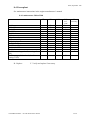
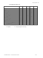
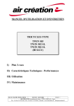
1
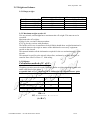
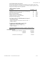
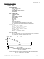
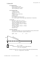
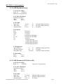
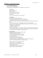
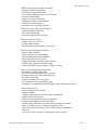
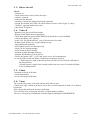
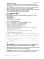
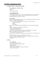
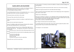
2005, September 13th
-User’s Manual
-Maintenance Manual
-Engine Manual
Section 1 to 7
Section 8
Annex
X-AIR
« HANUMAN »
X-AIR HANUMAN 602T AP (with Rotax 582 and parachute)
X-AIR HANUMAN 602T SP (with Rotax 582 without parachute)
X-AIR HANUMAN JABIRU AP (with Jabiru 2200 and parachute)
X-AIR HANUMAN JABIRU SP(with Jabiru 2200 without parachute)
X-AIR HANUMAN 912 AP (with Rotax 912 and parachute)
RAND-KAR sa Canal de la Martinière 44320 Frossay - France Tél.:+33 (0) 240 642 166 Fax : +33 (0) 240 641 522
Société au capital de 46 000 € siret : 384.220.695.00017 RM 44 APE 353 B FR 39.384.220.695
http///www.randkar.fr
E-mail : [email protected]
support technique [email protected]
X-AIR HANUMAN – use and maintenance manual
1 /55
2005, September 13th
SUMMARY
INTRODUCTION (Pages 5 to 9)
SECTION 1 : General points (Pages 11 to 15)
1-1 On-board documents
1-2 3 views drawings
1-3 Design features
1-3.1 Dimensions
1-3.2 Landing gear
1-3.3 Travel of control surfaces
1-3.4 Fuel tank
1-3.5 Wings
1-3.6 Fuselage
1-3.7 Empennage
1-3.8 Elevator
1-3.9 Direction
1-3.10 Seats
1-3.11 Controls
1-3.12 Diverse
1-4 Settings
SECTION 2 : Limitations (Pages 17 to 19)
2-1 Certification type
2-2 Pilot’s competence
2-3 Use conditions
2-4 Load factor
2-5 Weight and balance
2-6 Limited speeds
SECTION 3 : Powerplant (Pages 21 to 23)
3-1 Jabiru 2200
3-1.1 Manufacturer
3-1.2 Technical datas
3-1.3 Propeller
3-1.4 Noise pollution
3-2 Rotax 582
3-2.1 Manufacturer
3-2.2 Technical datas
3-2.3 Propeller
3-2.4 Noise pollution
3-3 Rotax 912
3-3.1 Manufacturer
3-3.2 Technical datas
3-3.3 Propeller
3-3.4 Noise pollution
X-AIR HANUMAN – use and maintenance manual
2 /55
2005, September 13th
SECTION 4 : Performances (Pages 25 to 27)
4-1 X-AIR Hanuman Jabiru
4-1.1 Service ceiling
4-1.2 Take off distance
4-1.3 Climb
4-1.4 Speeds
4-1.5 Engine off
4-1.6 Landing
4-2 X-AIR Hanuman 602T (Rotax 582)
4-2.1 Service ceiling
4-2.2 Take off distance
4-2.3 Climb
4-2.4 Speeds
4-2.5 Engine off
4-2.6 Landing
4-3 X-AIR Hanuman 912
4-3.1 Service ceiling
4-3.2 Take off distance
4-3.3 Climb
4-3.4 Speeds
4-3.5 Engine off
4-3.6 Landing
SECTION 5 : Standard procedure (Pages 29 to 35)
5-1 Pre-flight inspection
5-1.1 Cockpit
5-1.2 Engine
5-1.3 Airframe
5-2 Installation on board and starting engine
5-2.1 Engine cold
5-2.2 Engine hot
5-3 Check before take-off
5-4 Take-off
5-5 Climb
5-6 Turns
5-7 Flight in turbulences
5-8 Stall
5-8.1 Engine off
5-8.2 Full throttle
5-9 Cruise
5-10 Descent, approach, landing
5-11 Crosswind
5-12 Engine stop
5-13 Parking
5-14 Performances
X-AIR HANUMAN – use and maintenance manual
3 /55
2005, September 13th
SECTION 6 : Emergency procedures (Pages 37 to 40)
6-1 Engine failure, emergency landing
6-1.1 before take-off
6-1.2 on take-off
6-1.3 In flight
6-2 Fire
6-2.1 Engine fire
6-2.2 Cabin fire
6-2.3 Electric cables fire
6-3 Regulator failure
6-4 Landing without elevator
6-5 Emergency landing with engine
6-6 Emergency landing on water
6-7 Emergency landing on trees
6-8 Flight in hard rain
6-9 Flight in icing conditions
6-10 spin
6-11 Use of parachute
SECTION 7 : Accessories and options (Pages 41 to 44)
7-1 using advices
7-1.1 Skis
7-1.2 Floats
7-1.3 Banner
7-1.4 Crop spraying
7-2 Repercussion of options mounting
7-2.1 Skis
7-2.2 Floats
7-2.3 Banner
7-2.4 Crop spraying
7-2.5 Balistic parachute
SECTION 8 : Maintenance (Pages 45 to 55)
8-1 Taking down and transport
8-2 Airframe maintenance
8-3 Proppeller
8-4 Powerplant maintenance
8-4.1 Jabiru 2200
8-4.2 Rotax 912
8-4.3 Rotax 582
ANNEX : Engine manufacturer’s manual
X-AIR HANUMAN – use and maintenance manual
4 /55
2005, September 13th
INTRODUCTION
Dear fellow pilot,
Our congratulations and our thanks, for choosing our new X-AIR Hanuman Ultralight. We wish
you many pleasant hours of flight.
This maintenance and flight manual will help you achieve safe flying conditions.
Please read it attentively and follow all the instructions concerning assembly, preflight inspection,
in-flight operation and maintenance.
Feel free to contact your dealer for any additional information about your ultralight, and for any
remark you wish to make to improve the quality of this document, the service we can offer, or the
general safety of your flights.
This ultralight is an aircraft, and as such must be flight-tested by a certified instructor. All test
flights to be conducted in still air.
Never forget that you alone are responsible for the safe handling of your X-AIR Hanuman
Constant vigilance and attentiveness are essential.
Your own safety, the safety of your passenger and other fliers, as well as the future of ultralight
flying are at stake.
Many happy flights!
X-AIR HANUMAN – use and maintenance manual
5 /55
2005, September 13th
WARNING
Even in the best of conditions, ultralight flying may be hazardous. The user of this ultralight
acknowledges the existence of such hazards.
Before his first flight, the user must pledge to read this manual. He shall follow exactly the
instructions given.
He should be advised that the weight of any additional equipment increases the empty weight of
the aircraft and decreases its useful load accordingly -- since maximum weight cannot be exceeded.
The user pledges to carry out all the mandatory alterations specified in Rand Kar's regular
newsletters.
Any alterations or repair other than those specified by the manufacturer, or carried out without the
manufacturer's agreement shall void the warranty.
The user must be a 3 axis licensed Ultralight pilot.
Rand Kar Sarl cannot be held responsible for any incidents or accidents caused by improper
assembly, or reckless use of the ultralight, particularly when flying in bad weather, performing
aerobatics maneuvers, or maneuvers exceeding the flight envelope of the aircraft.
at ............................................................................., Date ..............................................................
Signed
Name and adress : ........................................................................................................
................................................................................................................................................................
....................................................................................................................................................
Aircraft type : ................................................................................................................................
Serial N°: .....................................................................
Engine : ………………………………………………..
EngineN° : ………………………………
Gearbox : ……………………….Gearbox ratio : …………………
Propeller : ………………………………..
Instruments : …………………………..
Other equipements : ………………………
X-AIR HANUMAN – use and maintenance manual
6 /55
2005, September 13th
TO MAKE WARRANTY EFFICIENT, THIS FORM HAVE TO BE RETURNED TO
RAND KAR sa Canal de la Martinière
F - 44320 FROSSAY - FRANCE
WARNING
Even in the best of conditions, ultralight flying may be hazardous. The user of this ultralight
acknowledges the existence of such hazards.
Before his first flight, the user must pledge to read this manual. He shall follow exactly the
instructions given.
He should be advised that the weight of any additional equipment increases the empty weight of
the aircraft and decreases its useful load accordingly -- since maximum weight cannot be exceeded.
The user pledges to carry out all the mandatory alterations specified in Rand Kar's regular
newsletters.
Any alterations or repair other than those specified by the manufacturer, or carried out without the
manufacturer's agreement shall void the warranty.
The user must be a licensed Ultralight pilot.
Rand Kar Sarl cannot be held responsible for any incidents or accidents caused by improper
assembly, or reckless use of the ultralight, particularly when flying in bad weather, performing
aerobatics maneuvers, or maneuvers exceeding the flight envelope of the aircraft;
at ............................................................................., Date ..............................................................
Signed
Name and adress : ........................................................................................................
................................................................................................................................................................
....................................................................................................................................................
Aircraft type : ................................................................................................................................
Serial N°: .....................................................................
Engine : ………………………………………………..
EngineN° : ………………………………
Gearbox : ……………………….Gearbox ratio : …………………
Propeller : ………………………………..
Instruments : …………………………..
Other equipements : ………………………
This form to be filled and returned to:
RAND KAR sa Canal de la Martinière
F - 44320 FROSSAY - FRANCE
X-AIR HANUMAN – use and maintenance manual
7 /55
2005, September 13th
Form to be filled and returned to after weighing operation of empty finished
aircraft:
C.of G calculation method.:
Aircraft must be horizontal
Weighing operation must be done with 3 similar weighing machines located each under every
wheel of the aircraft.
acceptable limit of C G = from 22 to 38,5 (cm)
Weight ( kg )
Front wheel
A
Main gear : left wheel
B
Main gear : right wheel
C
TOTAL
150 x A
CG = ------------- = -------(A+B+C)
Date:
Place:
Type of aircraft :
Serial Number
Identification sheet:
Max. empty weight :
Owner :
Signature :
Form to be filled and returned to after weighing operation of empty finished
aircraft to : RAND KAR sa Canal de la Martinière
F - 44320 FROSSAY - FRANCE
X-AIR HANUMAN – use and maintenance manual
8 /55
2005, September 13th
Property sheet
Owner N°1
Name and adress : ........................................................................................................
................................................................................................................................................................
....................................................................................................................................................
Observations........................................................................................................
................................................................................................................................................................
....................................................................................................................................................
Owner N°2
Name and adress : ........................................................................................................
................................................................................................................................................................
....................................................................................................................................................
Observations........................................................................................................
................................................................................................................................................................
....................................................................................................................................................
Buying date ……………………
Owner N°3
Name and adress : ........................................................................................................
................................................................................................................................................................
....................................................................................................................................................
Observations........................................................................................................
................................................................................................................................................................
....................................................................................................................................................
Buying date ……………………
Owner N°4
Name and adress : ........................................................................................................
................................................................................................................................................................
....................................................................................................................................................
Observations........................................................................................................
................................................................................................................................................................
....................................................................................................................................................
Buying date ……………………
Owner N°5
Name and adress : ........................................................................................................
................................................................................................................................................................
....................................................................................................................................................
Observations........................................................................................................
................................................................................................................................................................
....................................................................................................................................................
Buying date ……………………
X-AIR HANUMAN – use and maintenance manual
9 /55
2005, September 13th
X-AIR HANUMAN – use and maintenance manual
10 /55
2005, September 13th
SECTION 1 : General points
1-1 Board documents
-
The pilot will check before each flight the presence on board of all the necessary
documentation according the local regulations.
X-AIR HANUMAN – use and maintenance manual
11 /55
2005, September 13th
1-2 3 views drawings
X-AIR HANUMAN – use and maintenance manual
12 /55
2005, September 13th
1-3 Design features
1-3.1 dimensions :
Wing span
Length
Heigth
Surface
10.05 m
6.09 m
2.30 m
13.92 m²
1-3.2 Landing gear
Tricycle, brakes on main gear.
Wheel track width: 1.74 m
Wheel base :
1.50 m
Shock absorbers :
Bungee
Alloyed aluminium wheels
Tyres 4 plys 3.50 x 8
1-3.3 Travel of control surfaces
Elevator :
+30° -30°
Ailerons :
+43 –20°
Rudder :
+/-35°
Elevator trim : +/-35°
Flaps:
10°-20°-35°
1-3.4 Fuel tank
Behind the seats, capacity :
Usual capacity :
83 l
80 l
1-3.5 Wings
profile NACA 23012
Wings set at :
Twist :
Dihedral :
Sweep angle
4° at root
2°
2°
2°
Wing material
Leading edge
Trailing edge
Compression tubes
Tension cables
Wing tip tube
Wing struts
Battens
Fabric
aluminium Tube 64,4x2 mm (Sleeved with 60 x 1,6 )
aluminium Tube 50 x 2 mm (Sleeved with 45,3 x 1.5 )
aluminium Tube 38 x 1,6 mm
3 mm galva
aluminium Tube 25,4 x 1,6 mm
streamlined aluminium Rajhamsa 73 x 28 mm
20 per wing diam.12,7 x 1,2 mm
Dacron polyester 170 gr / m²
Ailerons material
Leading edge
Trailing edge
aluminium Tube 38 x 1,6 mm
aluminium Tube 12.7 x 1,2 mm
Flaps material
Leading edge
Trailing edge
aluminium Tube 38 x 1,6 mm
aluminium Tube 12,7 x 1,2 mm
X-AIR HANUMAN – use and maintenance manual
13 /55
2005, September 13th
1-3.6 Fuselage
cone rectangular section
Material
Main upper and lower tubes
Stiffeners
aluminium Tube 28,6 x 2 mm
aluminium Tube 18,6 x 1,1 mm
aluminium Tube 12,7 x 1,2 mm
1-3.7 Empennage
Flat profile
Material
Fabric :Dacron polyester 170 gr / m²
Horizontal empennage :
Leading edge
Trailing edge
Vertical empennage :
Leading edge
Trailing edge
aluminium Tube 25,4 x1,6 mm
aluminium Tube 25,4 x1,6 mm
aluminium Tube 25,4 x1,6 mm
aluminium Tube 25,4 x1,6 mm
1-3.8 Elevator
Flat profile
Material
Fabric :Dacron polyester 170 gr / m²
Leading edge aluminium Tube 25,4 x1,6 mm
Trailing edge aluminium Tube 25,4 x1,6 mm
1-3.9 Rudder
Flat profile
Material
Fabric :Dacron polyester 170 gr / m²
Leading edge aluminium Tube 25,4 x1,6 mm
Trailing edge aluminium Tube 25,4 x1,6 mm
1-3.10 Seats
Composite with foam
1-3.11 Controls
Type 3 axis
Rudder: action on rudder pedals linked to front wheel with rod end and to rudder
with cables
Handle stick
Manette de gaz
Elevator control
Aileron control
Flaps control
Double between legs
Double / left hand
push pull tube
3 mm cables + push-pull tubes
push-pull tubes
1-3.12 Diverse
Bolts: high quality 8.8 bichromated
3 mm stainless plates
powder coated painting
X-AIR HANUMAN – use and maintenance manual
14 /55
2005, September 13th
1-4 : Settings
The following elements can be subject to adjustment.
Elevator
To adjust the position of the stick relative to the pilot, the elevator control tube has
three holes drilled to allow length adjustment .
Choose the suitable hole and insert the bolt.
Add loctite.
Tighten nut to close fit.
Ailerons
Tuning is achieved by turning the turnbuckles supplied and adjust rod ends.
This will alter the position of the ailerons, which are normally lined up with the wing
lower surface.
If the ailerons have a strong inverse slope (trailing edge higher), the aircraft will tend
to nose up.
If the slope is smaller (trailing edge lower), the aircraft will tend to nose down.
Flaps
Lined up with the wing lower surface.
X-AIR HANUMAN – use and maintenance manual
15 /55
2005, September 13th
X-AIR HANUMAN – use and maintenance manual
16 /55
2005, September 13th
SECTION 2 : Limitations
2-1 Certification
X-AIR Hanuman comes under Class 3 of the Ultralight Aircraft Certification of November,
the 1rst, 1998, regulating flight authorization of Ultralights.
Certificates stipulated in sections R133-1 and following of the Code de L'Aviation Civile are
not required for ultralights, which are therefore exempted of any certification.
Each ultralight pilot must realize that he, and only he is responsible for the safe operation
and maintenance of his aircraft.
The X-AIR Hanuman can be used under such varied and diverse conditions that it is
impossible to give strict and all-inclusive instructions for its maintenance.
However, our present experience of the aircraft makes it possible to offer a realistic
maintenance program.
When in doubt, the owner should always seek advice from a competent professional.
Needless to say, we at RANDKAR welcome all your remarks; we will be pleased to answer
all your questions.
2-2 Required pilot competency
Student pilot license and orientation flight
Three-axis ultralight pilot license and further necessary training, as needed (an orientation
flight is mandatory in any case).
2-3 : Flight conditions
Day VFR, no icing conditions
2-4 Load factor
Max loads on controls
Rudder
1380 Newton
Elevator
480 Newton
Ailerons
1300 Newton
Flaps
960 Newton
On airframe
Limit :
+ 4 G (+6 ultimate)
- 2 G (-3 ultimate)
bank:
load factor
15°
1,04
Warning : Load factor changes when turn
30°
45° 60°
70°
1,15
1,41 2
3
X-AIR HANUMAN – use and maintenance manual
17 /55
2005, September 13th
2-5 Weight and balance
2-5.1 Empty weight
X-air Hanuman Jabiru SP
X-air Hanuman Jabiru AP
X-air Hanuman 602T SP
X-air Hanuman 602T AP
X-air Hanuman 912 AP
Basic empty weight (kg)
276
289
263
276
296
Max. empty weight (kg)
284
306,5
281
303,5
306,5
2-5.2 Maximum weight at take-off
Like any aircraft, an ultralight has a maximum take off weight. This must never be
exceeded.
Maximum take off weights:
450 kg for the versions without parachute
472,5 kg for the versions with parachute
The builder will in no circumstances be held liable should these weight limitations be
exceeded whatever the origin or nature of the additional or accessory equipment
carried on the aircraft.
This manual includes all the information required for the use and maintenance of the
aircraft.
This manual is specific to the aircraft it describes, and must be read by all users, as
stated in Parts 1and 2 of June 17, 1986 ruling.
2-5.3 Balance
Calculation method of C. of G.:
Aircraft must be horizontal
Weighing operation must be made with three similar weighing machine located each
under each wheel of the plane
acceptable limit of C G = between 222 to 385mm forward from reference point
Reference point : axel of the base tube
Weight ( kg )
Front wheel
A
Main gear : left wheel
B
Main gear : right wheel
C
150 x A
CG = ------------- = ………..
(A+B+C)
X-AIR HANUMAN – use and maintenance manual
18 /55
2005, September 13th
2-5.4 Changes made to the aircraft
Each owner is required to inform his local authority of any changes made to the
aircraft's characteristics as recorded in its type certificate (engine, propeller or any
other part) according to the local regulations
Added weight for options
OPTIONS
Weight Kg
Basic twin float set with fastenings and rudder
45
Amphibious twin float set with retract gear and fastenings
54
Hull with retract gear and sponsons
66
Snow skis with fastenings
9
Ballistic parachute with fastenings
12
Complete agri-spray set with fastenings
37
Microspray for agri-spraying
18
lbs
99,2
119
145,5
19,84
26,45
81,57
39,68
Total empty weight of X-AIR Hanuman is the sum of :
- Aircraft empty weight
- Weight of equipment ( instruments, intercom, radio ... )
- Weight of options
To obtain total loaded weight, you must add :
- Weight of crew ( pilot and passenger )
- Weight of fuel ( 0,72 kg, (1,59 lbs.) / liter )
- Weight of baggages
Total loaded weight must be less than, or equal to 450 kg (992 lbs. )
2-6 Limited speeds
-Maximum speed with flaps position 1
position 2
position 3
- maximum crosswind speed
X-AIR HANUMAN – use and maintenance manual
120 Km/h
110 Km/h
90 Km/h
25 Km/h
19 /55
2005, September 13th
X-AIR HANUMAN – use and maintenance manual
20 /55
2005, September 13th
SECTION 3 : Powerplant
3-1 Jabiru 2200
3-1.1 Manufacturer
Jabiru Aircraft Pty. Ltd.
P.O. Box 5168
BUNDABERG WEST QLD 4670
AUSTRALIA
3-1.2 Technical datas
4 cylinders, 4 stroke
2209 CC
80 hp (58KW) at 3300tr/mn
Double ignition
Air cooled
Direct drive
63 kg
Service life 1000 hours
Fuel : Unleaded 95 octane minimum or AVGAS 100 LL
Oil : automobile (follow engine manufacturer’s instructions)
3-1.3 Propeller
-Two blades DUC « SWIRL »
Material : composite, diameter : 1620mm
-Two blades ARPLAST « Ecoprop »
Material : composite, diameter : 1630mm
-Two blades ULX
Material : wood, diameter 1540mm
3-1.4 Noise pollution
The most unfavourable case is a noise heard under trajectory when aircraft
has just taken off, full throttle, optimum climb speed.
QNH : 1010
θ
: 17°C
50m
~300m
soundmeter
Lm = 69 dB a
Heard noise under trajectory Lh at a flight altitude h:
Lh = Lm – 22 log (h/50)
Example: heard noise by an observer located at 100m under the plane trajectory:
Lh = 69 - 22 log(100/50) = 62.37 dB a
X-AIR HANUMAN – use and maintenance manual
21 /55
2005, September 13th
3-2 Rotax 582
3-2.1 Manufacturer
Rotax Gesmbh & Co KG
Motorenfabrik, Welser STR 32
4623 Guunskirchen / Austria
3-2.2 Technical datas
2 cylinders 2 stroke
Water cooled
580,7 cc
Gearbox B :1/2,58
Gearbox C :1/3,47
Double ignition
Fuel : Mixture unleaded 95 octane + 2 stroke engine oil
Lubrication by mixture or separate oil.
%mixture following engine manufacturer’s instructions
Oil : 2 stroke engine oil following engine manufacturer’s instructions
3-2.3 Propeller
-Two blades ARPLAST « Ecoprop »
Material : composite, diamter : 1620mm
-Three blades ARPLAST « Ecoprop »
Material : composite, diameter : 1620mm
-Three blades DUC
Material : composite, diameter : 1620mm
-Two blades ULX
Material :wood
3-2.4 Noise pollution
The most unfavourable case is a noise heard under trajectory when aircraft
has just taken off, full throttle, optimum climb speed.
θ
QNH : 1010
: 17°C
50m
~300m
soundmeter
Lm = 71 dB a
Heard noise under trajectory Lh at a flight altitude h:
Lh = Lm – 22 log (h/50)
Example: heard noise by an observer located at 100m under the plane trajectory:
Lh = 69 - 22 log(100/50) = 64.38 dB a
X-AIR HANUMAN – use and maintenance manual
22 /55
2005, September 13th
3-3 Rotax 912
3-3.1 Manufacturer
Rotax Gesmbh & Co KG
Motorenfabrik, Welser STR 32
4623 Guunskirchen / Austria
3-3.2 Technical datas
4 cylinders 4 stroke
Air/Water/oil cooled
1211 cc
79 hp (58 KW) at 5800 tr/mn
Gearbox 1 :2,273
Double ignition
Fuel : Mixture unleaded 95 octane
Oil : 4 stroke engine oil following engine manufacturer’s instructions
3-3 Propeller
-Two blades ARPLAST « Ecoprop »
Material : composite, diamter : 1620mm
-Three blades ARPLAST « Ecoprop »
Material : composite, diameter : 1620mm
-Three blades DUC
Material : composite, diameter : 1620mm
-Two blades ULX
Material :wood
3-3.4 Noise pollution
The most unfavourable case is a noise heard under trajectory when aircraft
has just taken off, full throttle, optimum climb speed.
θ
QNH : 1010
: 17°C
50m
~300m
soundmeter
Lm = 71 dB a
Heard noise under trajectory Lh at a flight altitude h:
Lh = Lm – 22 log (h/50)
Example: heard noise by an observer located at 100m under the plane trajectory:
Lh = 69 - 22 log(100/50) = 64.38 dB a
X-AIR HANUMAN – use and maintenance manual
23 /55
2005, September 13th
X-AIR HANUMAN – use and maintenance manual
24 /55
2005, September 13th
SECTION 4 : Performances
4-1 X-AIR Hanuman Jabiru
4-1.1 Service ceiling
4500 m
( 14700 ft)
(take care of oxygen lack)
4-1.2 Take-off distance
With flaps position 2
-Run :
80 m
-DF15 :
190 m
4-1.3 Climb
-Best ratio :
-Best climb :
-Normal climb :
4-1.4 Speeds
VD
VNE
VNO
VC
VC eco
VA
VS
4,2 m/s
16 %
3,5 m/s
at
at
at
95 Km/h (flaps position1)
95 Km/h (flaps position1)
90 Km/h
220 Km/h
195 Km/h
175 Km/h
140 Km/h at 3000 Rpm
110 Km/h at 2500 Rpm
85 Km/h
72 Km/h no flaps
77 Km/h flaps position1
70 Km/h flaps position2
63 Km/h flaps position3
4-1.5 Engine off
-Maxi fineness :
-full flaps fineness
-Best glide ratio
11
at
6,5
at
2.5 m/sat
100 Km/h (flaps position1)
75 Km/h
100 Km/h (flaps position1)
4-1.6 Landing
Roll :
70 m
DA15 :
180 m
4-2 X-AIR Hanuman 602T (Rotax 582)
4-2.1 Service ceiling
4500 m
( 14700 ft)
(take care of oxygen lack)
4-2.2 Take off distance
with flaps position 2
-Run :
80 m
-DF15 :
190 m
4-2.3 Climb
-Best ratio :
-Best climb :
-Normal climb :
3,5 m/sat
14% at
3 m/s at
X-AIR HANUMAN – use and maintenance manual
90 Km/h (flaps position1)
90 Km/h (flaps position1)
85 Km/h
25 /55
2005, September 13th
4-2.4 Speeds
VD
VNE
VNO
VC
VC eco
VA
VS
210 Km/h
187 Km/h
170 Km/h
130 Km/h at 6200 Rpm
110 Km/h at 5500 Rpm
85 Km/h
72 Km/h (no flaps)
77 Km/h (flaps position1)
70 Km/h (flaps position2)
63 Km/h (flaps position3)
4-2.5 Engine off
-Max fineness:
11
at
-Full flaps fineness: 6,5
at
-Best glide ratio :
2.5 m/s at
100 Km/h (flaps position1)
75 Km/h
100 Km/h (flaps position1)
4-2.6 Landing
Roll :
70 m
DA15 :
180 m
4-3 X-AIR Hanuman 912
4-3.1 Service ceiling
4500 m
( 14700 ft)
(take care of oxygen lack)
4-3.2 Take-off distance
With flaps position 2
-Run :
80 m
-DF15 :
190 m
4-3.3 Climb
-Best ratio :
-Best climb :
-Normal climb :
4-3.4 Speeds
VD
VNE
VNO
VC
VC eco
VA
VS
4,2 m/s
16 %
3,5 m/s
at
at
at
95 Km/h (flaps position1)
95 Km/h (flaps position1)
90 Km/h
220 Km/h
195 Km/h
175 Km/h
140 Km/h at 5200 Rpm
120 Km/h at 4800 Rpm
85 Km/h
72 Km/h no flaps
77 Km/h flaps position1
70 Km/h flaps position2
63 Km/h flaps position3
X-AIR HANUMAN – use and maintenance manual
26 /55
2005, September 13th
4-3.5 Engine off
-Maxi fineness :
-full flaps fineness
-Best glide ratio
11
at
6,5
at
2.5 m/sat
100 Km/h (flaps position1)
75 Km/h
100 Km/h (flaps position1)
4-3.6 Landing
Roll :
70 m
DA15 :
170 m
X-AIR HANUMAN – use and maintenance manual
27 /55
2005, September 13th
X-AIR HANUMAN – use and maintenance manual
28 /55
2005, September 13th
SECTION 5 : Standard procedures
5-1 pre-flight inspection
This is where a safe flight begins.
A preflight inspection should be carried out before every take off.
5-1.1 Cabin
-Ignition switches off
-harness opened
-Seats fitted, cushions in place
-Free movement of controls
-Throttle off
-level in fuel tank checked, fuel cap torqued
5-1.2 Engine
Stand facing the engine and check:
- condition of propeller and propeller bolts and nuts
- reduction drive (no leakage, or excessive play in gears)
- engine hold down bolts (check that rubber mounts are seated flat against the base
plate)
- coolant circuit (for water-cooled engine) and level of coolant liquid
- proper operation of blower and condition of blower belt (for air-cooled engine)
- condition of coil support plate
- condition of spark-plug caps
-condition of fuel line
- water- and/or oil-radiator retaining bolts, intake muffler rubber mounts (optional)
- exhaust muffler hold down, condition of rubber mount and muffler holding strap
- the exhaust system for apparent or incipient cracks
5-1.3 Airframe
Starting from the left, facing the aircraft, check:
- fastenings of leading edge tube
- the wheel fastenings and the tyre pressure
- the upper and lower wing strut fastenings
- Jury struts fastening
- along the length of the wing struts
- the condition of the wing leading edge
- fastenings of compression tubes and drag cables inside the wing sail
- check safe and firm positioning of wing tip fairing
Walk around to the trailing edge and check:
- upper and lower rear strut fitting
- compression tube and drag cables fittings
- trailing edge fastening
- Aileron and aileron controls fastenings
- Flaps and flaps controls fastenings
X-AIR HANUMAN – use and maintenance manual
29 /55
2005, September 13th
Walk back along the fuselage and check:
- linkage on elevator bellcrank
- fastenings of stab fitting cables
- clevises on pushtubes to elevator bellcranks
- elevator attach fittings
- hinges of elevator and rudder
- condition of fabric on tail surfaces
- shackles on rudder cables
- fastenings of rear fuselage section
Walk over to the right side and check:
- elevator hinge on right side
- Stab cables fastenings
- general condition of tail surfaces
Move forward and check:
- rudder cables are crossed
- fuselage tubes fittings
- the wheel fastenings and the tyre pressure
Move along trailing edge and check:
- trailing edge fastening
- upper and lower rear strut fitting
- aileron fittings and aileron controls
- flaps fittings and flaps controls
- compression tubes and drag cables fittings
- Trailing edge fittings and fabric along
- check safe and firm positioning of wing tip fairing
Move to the cabin along leading edge
- fastenings of leading edge tube
- the wheel fastenings and the tyre pressure
- the upper and lower wing strut fastenings
- Jury struts fastening
- along the length of the wing struts
- the condition of the wing leading edge
- fastenings of compression tubes and drag cables inside the wing sail
In the cockpit, check:
- proper condition of seat bolts
- shackle safetied
- condition and tension of aileron cables and linkages
- rudder cables (must cross)
- tank vents open and tanks properly attached
- Fittings and conditions of all cabin tubes
- throttle cable at throttle lever and normal operation of throttle
- choke, gas filter, gas line, and electric pump if fitted
- airspeed indicator operation, AGL or MSL setting on altimeter
- fuel level
- well work of flaps, ailerons, rudder and elevator controls
X-AIR HANUMAN – use and maintenance manual
30 /55
2005, September 13th
5-2 Installation on board and starting engine
When sit in the cockpit, it’s IMPERATIVE to make ALL the following controls:
- Stick back
=>
elevator up
- Stick forward
=>
elevator down
- Stick left
=>
left aileron up and right aileron down
- Stick right
=>
right aileron up and left aileron down
- Push right foot
=>
rudder right
- Push left foot
=>
rudder left
-Fasten the safety harness
-Check the doors are locked
Before any engine starting action, it is essential to check there is nobody around the aircraft,
especially in the propeller area.
5-2.1 : Start engine cold
- check open tank vent
- give the squeeze bulb a few pumps, or start the electric pump (optional), to fill the
carburetor bowl
- check switch is "OFF"
- pull the propeller through 10 -15 turns (20 to 25 in very cold weather)
- choke lever "ON", throttle : closed
Note: fitting the optional priming set spares you this procedure.
- turn ignition "ON", clear all spectators from front and sides of propeller
- pull starter rope or push on electric starter button
This may be done while seated. Place left foot on rudder bar and hold starter handle
in both hands.
If this feels inconvenient, start from outside but make sure you have a competent
helper in the cockpit, ready to keep the aircraft from moving forward.
- as soon as engine is running, throttle to half-RPM and warm up for a few minutes,
moving choke to "OFF" gradually.
5-2.2 Start engine hot
- if the engine has been running quite recently, simply turn ignition "ON", choke
"OFF", throttle closed, and start.
The engine will start instantly.
- if more than 15 minutes have passed since the engine was stopped, start same as
just above, but with choke "ON".
Move choke to "OFF" immediately when engine starts.
CAUTION! NEVER TAKE OFF WITH CHOKE "ON":
This would make the engine lose power very quickly and might result in engine
stoppage on take off, with foreseeable consequences!
If the engine will not start cold, your spark plugs probably need replacing.
Otherwise, refer to the manufacturer's manual.
X-AIR HANUMAN – use and maintenance manual
31 /55
2005, September 13th
5. 3 : Before take-off
Check:
- altimeter set
- check controls move freely and to the stops
- trim tab : centered
- both seat belts fastened
- parachute: control box plugged and tested (optional)
- enough fuel in tank: never take off with less than 10 liters (2,64 US gals, 2,2 Imp.)
- Clearance: approach and runway clear
- radio check if required
5. 4 : Take-off
- Runway clear, and of sufficient length
- Run up at half RPM, check temperatures
- Check both ignition circuits at half-RPM. Drop should not exceed 300 RPM
- electric fuel pump "ON" (option)
- brake "ON" for full throttle test. (less if aircraft moves forward)
- throttle closed all the way : engine should not stop
- apply full throttle gradually
- stick slightly back to ease nosewheel up
- check you are tracking straight
- slowly rotate at about 70 km/h
- maintain 90 km/h through climb-out
- maintain full throttle to 150 m (500 ft )
- electric fuel pump "OFF" ("ON" may cause excess fuel consumption)
- to use the flaps on take off allows a reduction of minimum speed of:
5 km/h (approx 3 mph) in the first position (do not exceed 120 km/h with flaps in
the first position)
10 km/h (approx 6 mph) in the second position (do not exceed 110 km/h with flaps
in the second position)
5. 5 : Climb
- maintain air speed at 90 km/h
- check temperatures
- do not exceed specified limits
5. 6 : Turns
The aircraft enters turns easily and without much adverse yaw.
Control your angle of bank at all times, and at first, use little amounts of bank: 10° in final to
begin with.
Never forget that stall speed increases with bank.
You will soon come to enjoy the aircraft's excellent maneuverability.
However, always keep in mind that aerobatic flight in ultralights is PROHIBITED!
X-AIR HANUMAN – use and maintenance manual
32 /55
2005, September 13th
5. 7 : Flight in turbulences
At first, fly only in calm air or light winds. Flying in turbulence is advised only after a
certain degree of experience has been achieved. Keep your airspeed reasonable: 100 to 110
km/h is the recommended speed for comfortable flying in these conditions. Do not counter
all the little aircraft's excursions away from a perfectly level attitude.
X-AIR Hanuman has enough sweep-back and dihedral to give it positive stability.
In high winds, keep in mind the gradient effect, which may lower wind speed close to the
ground, and the inertia encountered upwind and downwind in the turn. Keep a reasonable
angle of bank, and your airspeed at or above 90 km/h (50 mph).
5. 8 : Stall
The best way to get to know your aircraft is to practice the stall. You will first have to climb
to a safe altitude, minimum 250m (820ft), clear the area by doing a 180-degree turn, and
begin the stall, engine at idle.
Practicing the stall and recovery will help you acquire the proper reactions and reduce
altitude lost in an unexpected stall.
5-8.1 : Stall power off (iddle)
First of all, make sure you are pointing upwind and the area is clear. When you come
to the stall speed indicated in the specs sheet, corrected as per load and density
altitude, the aircraft's handling becomes mushy, as the stick is pulled back slowly,
keeping the wings level and flight symmetrical.
Recovery is attained very simply by reducing wing incidence (release back pressure),
and adding power slowly.
As speed increases past 90km/h, pull back and level off gently.
Make sure you do not reach excessive speeds during recovery.
5-8. 2 : Stall full throttle
With power on, stall is achieved at a higher angle of attack and the break occurs
more abruptly; recovery in two seater configuration will lose you 30m (150ft).
5-9 Cruise
Choose the desired power setting for level flight between 90 and 140 km/h, depending on
model and load.
X-AIR HANUMAN – use and maintenance manual
33 /55
2005, September 13th
5-10 : Descent-Landing
To descend, reduce power for 90km/h at full load.
to use the flaps on landing allows:
-on first position, an increase of minimum speed of 5 km/h
(do not exceed 120 km/h with flaps on first position)
-on second position, a reduction of 2 km/h10 km/h
(do not exceed 110 km/h with flaps on second position)
-on third position, a reduction of 9 km/h
(do not exceed 90 km/h with flaps on third position)
Keep in mind that speed is controlled with the stick and angle of descent with the throttle.
Keep a safe margin and end your approach with a power off (idle) descent, then flare off.
In off-field landings, this procedure will allow you to retain enough altitude until the last
moment to avoid a hidden object, such as a fence or large rock....
A flat approach, airplane style, should be reserved to airfields with a well cleared, open
approach.
The flare-out itself is straightforward. Keep some power on for comfort, and keep the
aircraft tracking straight.
Remember: on an ultralight, the rudder remains effective down to very low speeds.
Once the main wheels are on the ground, keep pulling back on the stick until the nosewheel
touches down also.
This will slow down the aircraft faster and will keep the nosewheel from hitting a bump too
hard.
If your landing seems a bit chancy, never hesitate to add full power and go around.
The following is the easiest method to calculate best approach speed (V.A) for short field
landings:
V.A = (Vmin x 1,3) + 1/2 windspeed +(Vgusts - Vwindspeed)
Vmin is indicated in the specs sheet.
For example, at full load : WIND : 25 km/h (15 mph) ; GUSTS : 35km/h (22 mph)
V. A = (63x1,3) + 12,5 + (35-25)
V.A = 104,4 km/h
Check before landing
No aircraft on approach or ready to take-off
Brakes free
Iddle RPM, givrage, carb heat (if installed)
Fuel pump (if installed)
5-11 : Crosswind
Never take off with a 90° crosswind higher than indicated in the specs sheet: 25km/h
unless you are thoroughly experienced on your aircraft.
In crosswind landings, lower your wing into the wind, and add enough opposite rudder to
keep your aircraft straight down the strip (side slip).
Keep heading straight, touchdown with the upwind wheel first, then decrease your angle of
bank and lower the other wheel slowly.
This maneuver can be used with a minimal amount of practice.
X-AIR HANUMAN – use and maintenance manual
34 /55
2005, September 13th
IMPORTANT NOTICE:
Always keep in mind that any aircraft may experience unexpected engine failure.
Hence, make sure you always have enough altitude to be able to pick as safe an emergency
field as possible.
Never overfly built up or hostile areas such as forests, swamps, etc... without an added
margin of altitude to be able to reach safer terrain in case of engine failure.
The same applies to your choice of maneuvering speed, especially in phases of flight which
allow no room for improvisation (take off, climb out, landing).
Give yourself an ample safety margin; you will never regret it.
5-12 : Stopping the engine
On the ground:
Let the engine cool down for 30 seconds at half RPM before turning off the ignition.
- parking brake on
- radio and intercom: off
- all switches: off
- never close the fuel shut off (if fitted).
5- 13 : Parking and storage
(It is preferable to keep the X-AIR Hanuman parked inside a hangar)
If the X-AIR Hanuman has to be left outside unattended:
- point the aircraft into the wind, and put the brake on
- attach the stick with both safety harnesses
- immobilize the rudder with a control lock or other
- tie down the wings from the top of the struts to a "corkscrew "anchor in the ground
- similarly, tie down the propeller shaft
- block the wheels
- in Summer, shade the instrument panel with an aluminum/Mylar film.
5-14 : Performances (m = 450 kg)
The performance figures found in the following annexes represent averaged measured
values.
However, take into consideration that performance will vary with the power plant fitted on
each aircraft.
Performances at take off are greatly influenced by air density. Higher altitude and/or
temperature will affect results.
To clear 15m (approx.50ft) after take off, it is best to reach 85-90 km/h before you come
back on the stick.
This will mean a longer roll, but will eventually result in a shorter distance to clear 15m (50
ft).
Fuel consumption may vary with the mixture setting. Range will be estimated from the
amount of fuel in the tank, the wind and a minimum safety reserve of 30minutes.
Best gliding speed is lower if weight is lower. If the actual weight is 30% below maximum,
the best gliding speed will be 15% lower than normally specified.
Landing distance (to clear 15m) can be considerably shortened by side slipping, with stick
into the wind and opposite rudder. Practice with a qualified instructor is mandatory.
X-AIR HANUMAN – use and maintenance manual
35 /55
2005, September 13th
X-AIR HANUMAN – use and maintenance manual
36 /55
2005, September 13th
SECTION 6 : Emergency procedures
6-1 Engine failure - Emergency landing
6-1.1 : Before take-off, when taxiing
- throttle down
- brake
- cut off engine ignition
6-1.2 : During take-off
-set airspeed at 100 km/h
- land straight ahead; only minor course changes should be made, to avoid obstacles.
- do not attempt to fly back to the runway: more often than not, you do not have
enough height above ground to do so safely.
6-1.3:In flight
Note: the ultralight flight being operate always considering this possibility, you must
be close to a possible landing ground.
- check to see if the engine did not stop because of inadvertent action on:
- engine ignition switch
- throttle
- fuel shut off
- try to use the emergency fuel pump (black bulb) or start the electric fuel pump (if
fitted)
- airspeed: 100 km/h (you get 10 points of fineness)
- look for a suitable landing field
- seatbelts tight, helmets secured
- if you have enough altitude, flying down wind will allow to cover a greater
distance, increasing your chances of finding a suitable field.
- If the field is flat, land into the wind
- if the ground is reasonably level, putting stick forward all the way will shorten your
run
- if braking distance is restricted, full rudder into the wind
Note: In a 15 km/h wind (8 knots), the energy to be absorbed by the brakes will be
2,5 higher landing downwind than upwind.
- brake hard
6-2 Fire
6-2.1 : Engine fire
- close the fuel shut off (if fitted)
- stop the electric pump if it is on (if fitted)
- open full throttle
- cabin heating: off (if fitted)
- if possible, ask for help on the ground (fire brigade)
- land as soon as possible
X-AIR HANUMAN – use and maintenance manual
37 /55
2005, September 13th
6-2.2 : Fire in cockpit
- close heating and ventilation
- cut off auxiliary electric supply
- if necessary, cut off engine ignition and shut off the fuel line
- land as soon as possible
6-2.3 : Electric fire
- close heating and ventilation
- cut off auxiliary electric supply
- if necessary, cut off engine ignition and shut off the fuel line
- land as soon as possible
6-3 : Regulator failure
Failure of the battery regulator may cause overheating of the battery and gas release.
- pull out the charge fuse
- open the doors
- land as soon as possible
6-4 : Landing with elevator inoperative
- control the aircraft with the trim tab
- move the throttle very slowly while trimming with the tab
- pick a fairly long landing field
- set airspeed at 80 km/h (50mph) and 1,5m/s (300ft/mn) for final approach (depending on
wind and turbulence, a higher airspeed may be needed)
- flare with the trim tab, keeping off the ground as long as possible, without throttling back
- immediately on touchdown, cut power
6-5 : Emergency landing with engine
(due to weather conditions or imminent lack of fuel)
- look for an appropriate landing site: check for possible obstacles (trees; power lines,
fences); observe the slope of the field
- make a full 360° turn over the field; the amount and direction of drift during the turn will
indicate the speed and direction of the wind.
- overfly down low, into the wind, to make a thorough inspection of the field
- seatbelts tight, helmets secured
- make a normal landing
- immediately on touch down, cut engine ignition
- brake hard
6-6 : Emergency landing on water
CAUTION : it is difficult to estimate height above water!!
Get your passenger and yourself psychologically prepared for landing on water, and try to
pick a landing course that will make swimming ashore easiest.
Unlock the doors.
Be prepared to unfasten your safety harness. (Same for your passenger)
Touch down nose-up, as slowly and gently as possible.
Once in the water, stay calm; leave the aircraft without taking anything with you. X-AIR F
is made up of water resistant materials, so that it will almost always be possible to retrieve it
and get it in the air again with a thorough rinse in fresh water and a good dry out.
X-AIR HANUMAN – use and maintenance manual
38 /55
2005, September 13th
6-7 : Emergency landing on trees
Prefer one or several low, bushy trees. Belts and helmets tight.
Keep some speed on in final, as the air is often turbulent next to the trees. Pull up sharply to
break your speed as soon as you hear contact with the branches. Good luck!
6-8 : Flight in hard rain
If the windshield fogs up, wipe with a soft cotton rag.
Throttle down to limit wear on the propeller.
Try to fly away from the rain.
6-9 : Flight in icing conditions
Although flying in icing conditions is prohibited; you may be caught in such conditions.
Proceed as follows:
- carburetors heat: "ON" (if fitted)
-turn around or change altitude for a less critical air temperature
- increase power to reduce icing to minimum
- plan on landing on the nearest airfield; if ice is building up fast, land off-field
- ice on the leading edge increases your stall speed
- approach speed depending on thickness of ice: 80 to 90 km/h (50 to 56 mph); fly a
shallow, "airplane" type descent, with engine at high revs.
6-10 : Unvolontary spin
Use the following procedure to recover from an involuntary spin:
- opposite rudder, release when rotation stops
- let stick move freely (to neutral pitch, slight roll with the spin)
- pull out gently, staying within the flight envelope.
IMPORTANT NOTE
At very low speed, control the aircraft with rudder only.
6-11 : Use of parachute
the parachute is the last solution to save lives or limit injuries of pilot and passenger of the
airplane.
Its use can be necessary in extreme emergency situations like: collision in flight, structure or
control failure, faintness or incapability of the pilot, engine failure over very hostile land,
etc…
Use - - check : safety harness tight
- engine off
- press parachute handle immediately
- close fuel shut off (if fitted)
- radio you position
If you cannot get radio contact, switch to 121,50 MHz (emergency channel), and give your
position.
IMPORTANT : Never forget to remove the safety pin from the handle before take off and to
replace it after landing.
(For models fitted with a parachute)
If you are unable to regain control of the aircraft (collision, airframe failure) :
X-AIR HANUMAN – use and maintenance manual
39 /55
2005, September 13th
NOTE CONCERNING BALLISTIC PARACHUTES
Speed at opening exerts extremely high strains on the parachute.
The user should inquire from the parachute manufacturer if the characteristics of
parachute(s) are compatible with the performances of the airplane
Maintenance : Follow instructions of maintenance manual of parachute manufacturer.
X-AIR HANUMAN – use and maintenance manual
40 /55
2005, September 13th
SECTION 7 : Accessories and options
NOTE : Since RAND KAR is constantly developing new accessories, we reserve the right to alter
the design and specification of our products. We also reserve the right to substitute or withdraw any
kind of equipment presented in this document without any prior notice.
For complete, up-to-date information, contact RAND KAR or your X-AIR Hanuman dealer for the
latest comprehensive list of accessories.
7- 1 :List of manufacturer-authorized options and accessories for other,
special uses of X-AIR Hanuman
The two-seater model can be used for the special applications, professional or not, to be
found in the following, non exclusive list:
- Bi-floats, amphibian bi-floats, hull, amphibious hull, snow skis, all surveillance missions,
aerial photography, video or cinema, teledetection, towing of advertising banners, agrispraying of products in liquid or powder form, transportation of medical supplies or
casualties, pilot training or recreational flights, rental for diverse uses; the aircraft may be
equipped with a great number of accessories designed to increase comfort or safety.
No restriction need be applied in the fitting of special use accessories and options, other than
those mentioned in the installation manuals of those options.
Use advices: It is strongly recommended to get informations from an experienced pilot
in all these different following cases before flying with options.
7-1.1 : Skis
During preflight inspection, pay special attention to the sandow attachments and
those holding the skis in approach position.
During take off, make sure the runway does not have too much lateral slope, which
might cause the aircraft to deviate from the centerline.
Before landing, beware of faulty estimation of height above snow-covered terrain.
The absence of contrast, termed "white out", tends to give a deceptive impression of
height.
7-1.2 : Floats
At take off, choose a course as closely upwind as possible. Keep tracking straight as
you give power slowly. The stick must be kept at neutral, avoiding any waveinduced oscillations.
When taking off in a swell, choose a course that gives you the best compromise
between the wind direction and that of the waves.
In the hull version, keep the wings level when fast taxiing on water, to keep the
sponsons from hitting the water. For take off, stick back all the way, power on
slowly, to full.
The aircraft will "climb on the step" in a few yards. Then bring the stick forward to
level the aircraft.
Once the aircraft has reached a stable take off attitude, maintain this during
acceleration, observing the flight attitude rather than the position of the stick.
When X-AIR Hanuman has reached lift off speed, it will take off on its own. Do not
try to unstick it from the water, this could prove very ... wet! After accelerating in
ground effect, start a normal climb.
In flight, keep in mind the aircraft in hull version is often heavier than the land
version. Take this into account when selecting your approach speeds.
X-AIR HANUMAN – use and maintenance manual
41 /55
2005, September 13th
When landing, come in a little faster than with the land version, and prefer power-on
to power-off landings.
After the flare off, skim the water, with the same attitude as you had for take off,
always keep some power on and let the aircraft settle slowly rather than bringing it to
the stall.
As soon as the hull touches down, reduce power to idle and try to maintain the same
attitude until the aircraft stops.
When landing with power on, throttle down slowly to avoid burying the nose.
In case of engine failure, set up 100km/h and land upwind with the shallowest angle
possible.
Wind direction can be seen easily, since moored boats always face into the wind
when there is no current.
In all cases, take the direction of the swells into account.
When docking, never step on the forward part of the floats: if the aircraft is still
moving, this is sure to make it flip over!
A capsized aircraft should always be moved very slowly. Damage in this case
occurs almost always during towing or pulling out of the water.
Have the aircraft facing the shore, with the propeller parallel to the wings.
Attach ropes to the landing gear and the after end of the keel assembly, then pull very
slowly until the aircraft is back on its floats.
Immediately rinse off the airframe and the fabric parts in fresh water, and the engine
in diesel oil. The airframe's aluminum alloy is remarkably resistant to salt water, as
long as you observe correct seaplane maintenance procedures daily, and especially
after a capsize.
Before a flight to altitudes greater than 500m (1600ft ) loosen the access hatches to
avoid problems during descent; pressure differential in the floats or hull might cause
damage on landing.
A few words on porpoising, dreaded by the novice seaplane pilot : it is an oscillation
happening mainly on take off, which tends to increase and may even cause the
aircraft to flip over.
It is generated by faulty pitch control (too much nose up or down ) at the moment
when the aircraft climbs on the step.
To stop porpoising, you must either abort take off, or increase the pitch deliberately
before reducing it to normal.
Never try to "hunt" with the stick (countering the pitch, up, then down). This would
only amplify the oscillation.
X-AIR HANUMAN – use and maintenance manual
42 /55
2005, September 13th
7-1.3 Banner towing
Make sure the tow hook is properly secured on the centerline.
Two technics are possible for towing:
- Direct pick up of the banner at take off, with a minimum rope length of 70m (230
ft) The banner is stretched in front of you along the center of the runway.
As soon as the banner leaves the ground, level off and accelerate, and stay prepared
to release all through take off.
- Banner pick up with a hook :
This is a more complex maneuver, but it is safer than the one described above.
(Engine failure during take off while towing a banner requires lightning reflexes).
Line up at 100km/h to pick up the banner, and watch for any drift of the hook. Climb
immediately after the banner has been picked up.
While towing, maintain 70-80km/h (45-50mph) to keep the letters nicely spaced.
In case of engine failure, release the banner as soon as you are over a vacant zone.
7-1.4 : Crop spraying
All information concerning maintenance of this equipment will be found in the
relevant manual.
The increased drag due to this equipment lowers your maximum speed by +or15km/h (9mph).
You are advised to take on no more than 120 liters (32US, 26 Imp gals). Keep in
mind that low flight is the most difficult and dangerous kind of flying.
Before spraying, check all the obstacles along the flight path.
7-1.5 : Photography, movie and video equipments
No heavy outside equipment shall be installed outboard of the upper wing strut
fitting. Please contact RAND KAR for any such installation.
No additional safety recommendation is needed.
However, note that for all uses calling for photo, movie or video equipment, we
advise that it be very safely secured, as it might cause serious damage or injury if it
came loose at landing or in flight.
X-AIR HANUMAN – use and maintenance manual
43 /55
2005, September 13th
7- 2 : Effects of the equipment mentioned above on flight parameters and
performances of the aircraft
7-2.1 Snow skis
Top speed is approximately 10km/h lower (6mph).
7-2.2 Floats or hull ( only with engines of more than 60 hp)
Top speed at maximum load in decreased by approximately 10km/h (6mph) due to
additional drag.
Take off distance at maximum load ..................... 150 m
Maximum speed.........................................
120km/h
Minimum sink ......................
4m/s at 70km/h
7-2.3 Banner towing set (with engines of more than 60 hp only)
Banner towing is basically a question of practice. The effect of a banner depends on
its size.
7-2.4 Agri-spraying equipment (with engines of more than 60 cv only)
Top speed at maximum load is lowered by approximately 10km/h (6mph).
7-2.5 Ballistic parachute
IMPORTANT NOTE : Installation of the parachute must be done under supervision
by, and with the express agreement of RAND KAR. We reserve the right to ask for
removal of this equipment in case of faulty installation by the user.
You are strongly advised to send RAND KAR photographs of your installation.
Using additional options and accessories decreases the useful load.
Always make sure you do not exceed the maximum load at take off.
Generally, when flying at maximum load you should always observe the mandatory
airspeed compatible with the load and prevailing weather conditions (altitude,
atmospheric pressure, temperature).
X-AIR HANUMAN – use and maintenance manual
44 /55
2005, September 13th
SECTION 8 : Maintenance
8-1 Taking down and transport
Preparing the aircraft for transport on a trailer or for off airport storage is a simple operation
that needs two people and about 1/2 an hour.
It’s recommended to proceed as follows:
To avoid losing the parts removed, re-fit immediately the screws, nuts, pins and rings back
into their own parts immediately on removal.
-Disconnect ailerons control tubes in the cockpit.
-Disconnect flaps control tubes from their horns.
-Each wing strut and jury strut has its own place, so mark them for easy assembly.
-Remove the jury struts from the wings struts.
In case of a ventimeter sender on the wing strut, disconnect the ventimeter hose from the
instrument and roll it on the wing strut.
-One person hold up the wing at its tip. It will help if they lightly move or twist the wing,
following
the suggestions of his partner to make the pins removal easier.
Disconnect the rear wing strut from the trailing edge.
Disconnect the front wing strut from the leading edge.
Disconnect the leading edge.
Disconnect the trailing edge.
Remove the wing.
Disconnect the wing struts from the cockpit base.
-Proceed the same way for the second wing.
In some countries, it’s necessary remove the stabiliser, to reduce the width, according to the
road regulations:
-Disconnect the tips of the elevator fork from their control levers on the elevator assembly.
-Remove the rings that secure the lower stab cables under the fuselage.
-Screw the bolt that fit the upper stabiliser cables in the fin leading edge to have enough lack
in these cables to remove them.
-Remove the two half-stabiliser.
In the case of transport on a trailer, it is very important to protect with foam all the parts of
the aircraft that are in contact with other parts of the aircraft or in contact with the trailer,
most damage to aircraft is done on due to travelling vibrations and accidents.
Fit the cables to avoid loss. Immobilize the rudder.
Don’t forget to check the load a last time before leaving.
To assemble, proceed in the reverse order, use new nuts, control the path of the cables in
their pulleys and don’t forget to make the pre-flight inspection before flying.
X-AIR HANUMAN – use and maintenance manual
45 /55
2005, September 13th
8-2 Airframe maintenance
( to be carried out periodically as per table below)
The following maintenance tables never can replace the
pre-flight check, obligatory before every take-off.
Nota: these maintenance periods concern only the aircrafts flying under a continental climate
and being stocked under hangar. The aircrafts submitted to other conditions will have to be
more frequently checked.
Périodicity
1 month 6 month
50 h
150 h
1 year
300 h
2 years
600 h
V
Wings, control surfaces and empennage fabrics
5 years
900 h
C
Fork and landing gear
Tyres pressure (1.8)
Tyres wear
Brakes wear
Front fork and main gear shok absorbers
V
V
V
V
V
Windsreen
Controls
Ailerons cables
Ailerons tubes and tubes-and socket-joints
Rudder cables
Handle stick joint
Elevator control
Choke and throttle cables
Flaps control
Electric wiring and fuel line
Take care of scrapping and wear
Electric wires
Battery
Fuel hoses
Handle fuel pump
Fuel filter
Fuel tank
Control surfaces, trim, mobile parts
axels
Bellcrank / quick links
Câble trim
V
V
V
L
V
V
V
L
L
V
V
L
V
V
V
V
V
R
R
R
V
L
C
C
C
V
L
V
Bolts
NOTA :
C
C
C
C
C
C
C
V
R
L
C
C
= Verify and replace if necessary
= Replace
= Lubricate, verify and replace if necessary
= Control by a competent professional and replace if necessary
X-AIR HANUMAN – use and maintenance manual
46 /55
2005, September 13th
Maintenance every 50 hours or 1 month
Périodicity
1 month Date
50 h
control
Date
control
Date
control
Wings, control surfaces and empennage fabrics
Fork and landing gear
Tyres pressure (1.8)
Tyres wear
Brakes wear
Front fork and main gear shok absorbers
V
V
V
V
Windsreen
Controls
Ailerons cables
Ailerons tubes and tubes-and socket-joints
Rudder cables
Handle stick joint
Elevator control
Choke and throttle cables
Flaps control
Electric wiring and fuel line
Take care of scrapping and wear
Electric wires
Battery
Fuel hoses
Handle fuel pump
Fuel filter
Fuel tank
Control surfaces, trim, mobile parts
axels
Bellcrank / quick links
Câble trim
V
V
V
L
V
V
V
V
V
V
L
V
L
Bolts
NOTA :
V
R
L
C
= Verify and replace if necessary
= Replace
= Lubricate, verify and replace if necessary
= Control by a competent professional and replace if necessary
X-AIR HANUMAN – use and maintenance manual
47 /55
Date
control
2005, September 13th
Maintenance every 150 hours or 6 month
Périodicity
6 month Date
150 h control
Date
control
Date
control
Wings, control surfaces and empennage fabrics
Fork and landing gear
Tyres pressure (1.8)
Tyres wear
Brakes wear
Front fork and main gear shok absorbers
V
V
V
V
Windsreen
Controls
Ailerons cables
Ailerons tubes and tubes-and socket-joints
Rudder cables
Handle stick joint
Elevator control
Choke and throttle cables
Flaps control
Electric wiring and fuel line
Take care of scrapping and wear
Electric wires
Battery
Fuel hoses
Handle fuel pump
Fuel filter
Fuel tank
Control surfaces, trim, mobile parts
axels
Bellcrank / quick links
Câble trim
L
V
L
V
L
L
V
V
V
V
V
R
V
L
V
L
Bolts
NOTA :
V
R
L
C
= Verify and replace if necessary
= Replace
= Lubricate, verify and replace if necessary
= Control by a competent professional and replace if necessary
X-AIR HANUMAN – use and maintenance manual
48 /55
Date
control
2005, September 13th
Maintenance every 300 h or 1 year
Périodicity
Wings, control surfaces and empennage fabrics
1 year
300 h
Date
control
Date
control
Date
control
V
Fork and landing gear
Tyres pressure (1.8)
Tyres wear
Brakes wear
Front fork and main gear shok absorbers
V
V
V
V
Windsreen
Controls
Ailerons cables
Ailerons tubes and tubes-and socket-joints
Rudder cables
Handle stick joint
Elevator control
Choke and throttle cables
Flaps control
Electric wiring and fuel line
Take care of scrapping and wear
Electric wires
Battery
Fuel hoses
Handle fuel pump
Fuel filter
Fuel tank
L
V
L
V
L
L
V
V
V
R
V
R
V
Control surfaces, trim, mobile parts
axels
Bellcrank / quick links
Câble trim
L
V
L
Bolts
V
NOTA :
V
R
L
C
= Verify and replace if necessary
= Replace
= Lubricate, verify and replace if necessary
= Control by a competent professional and replace if necessary
X-AIR HANUMAN – use and maintenance manual
49 /55
Date
control
2005, September 13th
Maintenance every 600 h or 2years
Périodicity
Wings, control surfaces and empennage fabrics
2 years
600 h
Date
control
Date
control
Date
control
V
Fork and landing gear
Tyres pressure (1.8)
Tyres wear
Brakes wear
Front fork and main gear shok absorbers
V
V
V
V
Windsreen
Controls
Ailerons cables
Ailerons tubes and tubes-and socket-joints
Rudder cables
Handle stick joint
Elevator control
Choke and throttle cables
Flaps control
Electric wiring and fuel line
Take care of scrapping and wear
Electric wires
Battery
Fuel hoses
Handle fuel pump
Fuel filter
Fuel tank
L
V
L
L
V
L
V
V
V
V
R
R
V
Control surfaces, trim, mobile parts
axels
Bellcrank / quick links
Câble trim
L
V
L
Bolts
V
NOTA :
V
R
L
C
= Verify and replace if necessary
= Replace
= Lubricate, verify and replace if necessary
= Control by a competent professional and replace if necessary
X-AIR HANUMAN – use and maintenance manual
50 /55
Date
control
2005, September 13th
Maintenance every 900 h or 5 years
Périodicity
Wings, control surfaces and empennage fabrics
5 years
900 h
Date
control
Date
control
Date
control
C
Fork and landing gear
Tyres pressure (1.8)
Tyres wear
Brakes wear
Front fork and main gear shok absorbers
V
V
V
V
V
Windsreen
Controls
Ailerons cables
Ailerons tubes and tubes-and socket-joints
Rudder cables
Handle stick joint
Elevator control
Choke and throttle cables
Flaps control
Electric wiring and fuel line
Take care of scrapping and wear
Electric wires
Battery
Fuel hoses
Handle fuel pump
Fuel filter
Fuel tank
C
C
C
C
C
C
C
V
V
R
R
R
V
Control surfaces, trim, mobile parts
axels
Bellcrank / quick links
Câble trim
C
C
C
Bolts
C
NOTA :
V
R
L
C
= Verify and replace if necessary
= Replace
= Lubricate, verify and replace if necessary
= Control by a competent professional and replace if necessary
8-3 Propeller
-
Frequentnly wash the blades with soapy water
Repare all the little cracks with epoxy resin and sand
Torque of M8 bolts:1.2 Kg/m
X-AIR HANUMAN – use and maintenance manual
51 /55
Date
control
2005, September 13th
8-4 Powerplant
See maintenance instructions in the engine manufacturer’s manual
8-4.1 maintenance Jabiru 2200
1- Oil
2- Fuel filter
3- Air filter
4- Oil filter
5- Oil leaks
6- Hoses
7- Intake - exhaust
8- Electric wiring
9- Spark plugs
10- Cylinder pressure
11- Oil venting hose
12- throttle drive
13- Carburettor
14- Valves setting (after first setting of
25h)
15- Torquing cylinder head (after first
setting of 25h)
R : Replace
25h
50h
V
R
R
V
100h
200h
or 1
year
If
necessary
R
R
V
V
V
R
Clamps
V
V
R
V
V
Leaks
V
V
Purge
V
V
V : Verify and replace if necessary
X-AIR HANUMAN – use and maintenance manual
52 /55
2005, September 13th
8-4.2 maintenance Rotax 912
25h
Oil
Fuel filter
Air filter
Oil filter
Lubrication line
Cooling line
Intake-exhaust
Electrics and ignition
Spark plugs
compressions
Throttle drive
Carburettors-fuel line
Engine Silent-blocs
Engine bolts
Gearbox
Valve spring tension (BT912-04)
Float valve (BT912-04)
R : Replace
R
V
V
R
V
V
V
V
V
50h
100h
ou 1 an
R
200h
600h
R
R
R
R
R
V
V
V
V
V
V
V
V
V
V
V : Verify and replace if necessary
X-AIR HANUMAN – use and maintenance manual
53 /55
2005, September 13th
Maintenance Rotax engines
1 Tighten up the cylinder head nuts
2 Tighten up the exhaust pipe screws
3 Check the handlestarter rope
4 Check the crown wheel of electric starter
5 Check spark plugs
6 Change spark plugs
7 Check and clean the spark plug covers
8 Check ignition advance
9 Check the contact breakers
10 Check ignition alternator
11 Change contact breakers and capacitors
12 Check the belt tension
13 Grease exhaust elbow (high temperature grease)
14 Change exhaust springs
15 Lubricate the control cables
16 Check balance and tracking of propeller
17 Change the nuts of the proppeller
18 Clean and oil air filters
19 Clean fuel filter
20 Change fuel filter
21 Check carburettors, adjust idle and throttle cables
22 Clean the cabs and check the inside parts
23 Change needles and needles jets
24 Clean and check the fuel pump
25 Check oil level in gearbox
26 Change oil in the gearbox
27 Check and change if necessary the lock washers of the gearbox (gearbox A orB)
28 Check the 4 fitting screws of gearbox adaptor (gearbox A)
2H 10H 12,5H 25H 50H
1 X
1 X
X
X
X
X
X
X
2
X
2
X
X
3
4
75H 100H 125H 150H 175H 200H 225H 250H 275H
X
X
X
X
X
X
X
X
X
X
X
X
X
X
X
X
X
X
X
X
X
X
X
X
X
X
X
X
X
X
X
X
X
X
X
X
X
X
X
X
X
X
X
X
X
X
X
X
X
X
X
X
X
X
X
X
X
X
X
X
X
X
X
X
X
X
X
X
X
X
X
X
X
X
X
X
X
X
X
X
X
X
X
X
X
X
X
X
X
X
X
X
X
X
X
X
X
X
X
X
X
X
X
X
X
X
X
X
X
X
X
X
X
X
X
X
X
X
X
X
X
X
2H 10H 12,5H 25H 50H 75H 100H 125H 150H 175H 200H 225H 250H 275H
X-AIR HANUMAN – use and maintenance manual
54 /55
2005, September 13th
29 Change the lubricating oil of water pump
30 Check cylinder heads and pistons
31 Check the gap of piston rings
32 Check pistons diameter
33 Check the wear of piston rings
34 Check vertical gap of rectangular piston ring
35 Check cylinders diameter
36 Check ovalization of cylinders
37 Change the following gaskets : base, cylinder head, intake and exhaust
38 Check pistons axles and bearings
39 Check the crankcase and change the oil seals
40 Major overhaul
5
6
8
8
8
8
8
9
X
X
X7
X7
X7
X7
X7
X
10
1 - And after each gasket change
2 - And aftyer each change of contact breakers
3 - And after each reparing
4 - Following engine builder’s instructions
5 - If carbon deposit > 0,5mm, clean
6 - Clean pistons and piston rings
7 - If use in dusty environment
8 - see B/S 5 UL 91
9 - If cylinders are removed
10 - Contact your ROTAX dealer
X-AIR HANUMAN – use and maintenance manual
55 /55
X
X
X
X7
X7
X7
X7
X7
X
X
X
X
X
X
X
X
X
X
X
X
X
X
X7
X7
X7
X7
X7
X
X
X
X7
X7
X7
X7
X7
X