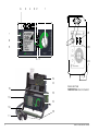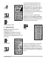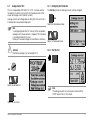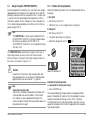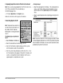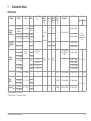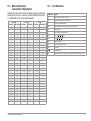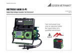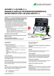
1
Operating Instructions
PROFITEST 204⏐+, 204⏐L+, 204HP, 204HV
Test Instrument for EN 60204 / DIN VDE 0113
Test instrument
may only be
operated under
supervision of a
qualified electrician!
3-348-781-03
23/9.15
6
5
4
3 2
1
22
7
8
9
23
10 11
24
15
14
13
13
Connector Panel
PROFITEST 204+: Basic Instrument
12
12
16
18
17
2
GMC-I Messtechnik GmbH
17
18
11
7
19
STORE
20
START RPC
21
START RINS
1
2
3
4
5
6
7
8
9
10
11
12
13
14
15
Remote Control
PROFITEST 204+: Test Probes
!
Attention!
The ventilation slots at the bottom of the housing (24)
and in the connector panel of the basic instrument must
remain unobstructed!
GMC-I Messtechnik GmbH
16
17
18
19
20
21
22
23
24
Function selector switch
key
key
Printer port
Connector socket for RS 232 interface
LCD window
Signal lamp: test passed (green) / test failed (red)
MENU key
Help key / save key
Start key for selected test
Signal lamp “test in progress” (yellow)
Push-buttons (left and right) for releasing the handle from its snap-in
position
Push-buttons (left and right) for releasing the lid
Lid
Accessory input module SECUTEST (P)SI
(not included in standard equipment)
Carrying handle and tilt stand
Test probe with integrated controls
Test probe with integrated fuse
Key for saving measurement value
Key for starting protective conductor measurement
Key for starting insulation measurement
Mains connector
Power supply connector for high-voltage module (max. 6 A)
Ventilation slots
3
8
7
4
5
High-Voltage Pistol with Switch
1
6
I
2
0
!
1
2
3
4
5
6
7
3
PROFITEST 204 HP/HV High-Voltage Module
Connector Panel
4
8
Inlet connector for power supply to high-voltage module with insert for fuse
Key switch for the prevention of unauthorized use
Terminals for external signal lamps (see chapter 3.1.3, page 15)
When green signal lamp is illuminated, high-voltage module is ready for
operation
When red signal lamp is illuminated, high-voltage module is ready to be
activated. Caution, danger!
Permanently attached measurement cable
Trigger (switch).
As opposed to high-voltage pistols without switch, the high-voltage switching pistol is identified with a red clamping ring on the connector cable underneath the handle.
Recessed safety test probe
GMC-I Messtechnik GmbH
Items Shipped with the Instrument
If you have two sets of operating instructions with different issue dates:
Use only the newest operating instructions.
The issue date appears on the title page underneath the order
number (3-348-781-xx), e.g. 17/9.10 means: 17th revision,
September 2010.
PC Program WinProfi for communication with PROFITEST 204+
The free PC starter software WinProfi* is used for communication
with your PROFITEST 204+ test instrument. WinProfi is available on
our homepage with the following content and functions:
• up-to-date test instrument software
– for loading a different language for the user interface
– for loading an updated software version
• Transmission of measurement data from the test instrument to
the PC
• preparation and modification of templates for test reports at the
PC and transmission of the templates to the test instrument
• preparation, printout and filing of test reports at the PC
The following interface cables and/or converters are required for
communication between test instrument and PC:
– Z3241
RS232 (tester*) – RS232 (PC)
– RS232-USB Converter (Z501L)
RS232 (tester*) – USB (PC)
Notes on SECUTEST SI+ Operating Instructions
The SECUTEST SI+ module is used together with the
PROFITEST 204+ exclusively for entering comments at the alphanumeric keypad.
The following chapters from the operating instructions included
with the SECUTEST SI+ (3-349-613-15) are relevant for operation
with the PROFITEST 204+:
• Chapter 2:
Safety Features and Precautions
• Chapters 3.1 and 3.2: Inserting and activating the SI Module
• Chapter 10:
Characteristic Values
• Chapter 11:
Maintenance
• Chapter 12:
Repair and Replacement Parts Service
• Chapter 13:
Product Support
The following functions are not active, and are only sensible in
combination with the SECUTEST... test instrument:
• Display and save reports
• Statistics
• Utilization in combination with a barcode scanner
* not possible via the RS232 terminal of a connected SECUTEST SI+
Up-to-date PC software (free of charge starter or demo software
for data management, report and list generation) is available from
our homepage for download.
* WinProfi is currently applicable up to Windows 7 (32 Bit)
GMC-I Messtechnik GmbH
5
Contents
Page
1
1.1
1.2
Applications ..................................................................................8
PROFITEST 204+ ...........................................................................8
PROFITEST 204L ...........................................................................8
2
2.1
2.1.1
2.1.2
2.1.3
2.1.4
Safety Features and Precautions ..................................................9
Meanings of Symbols ....................................................................10
Symbols on the Instrument ............................................................10
Symbols in the Operating Instructions .............................................10
Symbols which Appear at the PROFITEST 204+ Display .................10
Symbols which Appear at the Display of the
PROFITEST 204HP/HV High-Voltage Module ...................................11
Special Safety Precautions and Instructions for the
PROFITEST 204HP/HV High-Voltage Module ...................................12
2.2
3
3.1
3.1.1
3.1.2
3.1.3
3.2
3.3
3.4
3.5
3.6
3.7
3.7.1
3.7.2
3.7.3
3.7.4
3.7.5
6
Initial Start-Up ............................................................................14
Start-Up of the Optional High-Voltage Module .................................14
Mounting the High-Voltage Module to the Basic Instrument .............14
The Key Switch .............................................................................15
Indication of Operating States ........................................................15
Mounting the Instruments to the Optional Caddy .............................16
Connecting the PROFITEST204+ to 230 V Mains Power .................17
Connecting the High-Voltage Module to 230 V Mains Power ............17
Operating Software .......................................................................18
Online Help ...................................................................................18
Setup ...........................................................................................19
Adjusting Contrast and LCD Illumination .........................................19
Setting Time and Date ...................................................................20
Configuring the Signal Generator ....................................................20
Performing the Self-Test ................................................................21
Uploading the Desired Language or a Software Update ....................23
Contents
Page
4
4.1
4.1.1
4.1.2
4.2
4.2.1
4.2.2
4.3
4.3.1
4.3.2
4.4
4.4.1
4.4.2
4.5
4.5.1
4.5.2
4.5.3
4.5.4
4.5.5
Testing Machines in Accordance with DIN VDE 0113 and EN 60 204 ....26
Protective Conductor Test .............................................................26
Configuring Test Parameters .........................................................27
Start the Test ...............................................................................28
Insulation Resistance Test .............................................................29
Configuring Test Parameters .........................................................30
Start the Test ...............................................................................30
Leakage Current Test ....................................................................31
Configuring Test Parameters .........................................................31
Start the Test ...............................................................................31
Voltage Measurement (protection against residual voltage) ..............33
Configuring Test Parameters .........................................................34
Start the Test ...............................................................................34
Voltage Test (option: PROFITEST 204HP/HV) ..................................35
Functions Test (test preparation) ....................................................35
Configuring Test Parameters .........................................................37
Test Sequence .............................................................................39
Pulse Control Mode .......................................................................41
Ending the Voltage Test .................................................................41
5
5.1
5.1.1
5.1.2
5.1.3
5.2
5.3
5.3.1
5.3.2
5.4
5.5
Processing, Transmitting and Deleting Data ..............................42
Selecting a System .......................................................................42
Entering a Description ...................................................................43
Copying Descriptions ....................................................................43
Deleting a Description ...................................................................43
Data Processing (viewing measured values) ....................................44
Data Reorganization ......................................................................44
Deleting Recorded Data .................................................................44
Memory Test ................................................................................45
Clearing Memory .......................................................................45
Data Transmission ........................................................................46
GMC-I Messtechnik GmbH
Contents
Page
Contents
Page
6
6.1
6.2
6.3
6.4
6.4.1
6.4.2
6.4.3
Printing, Uploading and Creating Reports .................................. 48
Print Values (PSI) / Print a Report ................................................... 48
Selecting a Form for Report Printing .............................................. 49
Uploading a Report Form .............................................................. 50
Report Form Generating Program .................................................. 53
List of Code Words and their Meanings .......................................... 53
Report Layouts ............................................................................. 54
Uploading a Report Form to the Test Instrument ............................. 54
11.5.3
11.6
11.7
11.8
Replacing Bulbs at the External Signal Lamps ................................ 68
Software ...................................................................................... 68
Recalibration ................................................................................ 69
Device Return and Environmentally Compatible Disposal ................. 69
12
12.1
12.2
7
Characteristic Values ................................................................. 55
8
Setting Ranges for Parameters and Standard Values per DIN VDE ........57
12.3
12.4
Appendix .................................................................................... 70
Checklist for the High-Voltage Test ................................................ 70
Minimum Display Values
in Consideration of Operating Error ................................................ 71
List of Abbreviations ..................................................................... 71
Index ........................................................................................... 72
9
9.1
9.1.1
9.1.2
9.1.3
9.2
9.2.1
Data Interfaces ........................................................................... 60
RS 232 Serial Interface ................................................................. 60
Software Analysis of Measurement Results .................................... 60
Interface Definition and Protocol .................................................... 60
Connector Pin Assignments .......................................................... 60
Parallel Interface (printer port) ....................................................... 60
Connector Pin Assignments ......................................................... 60
10
Signals / Error Messages, Causes and Remedies ...................... 61
13
Repair and Replacement Parts Service
Calibration Center and Rental Instrument Service ..................... 74
14
Product Support ......................................................................... 74
11
11.1
11.1.1
11.1.2
Maintenance .............................................................................. 66
Replacing Fuses ........................................................................... 66
Replacing the Mains Fuse ............................................................. 66
Replacing the Measuring Circuit Fuse in the
Test Probe at the PROFITEST 204+ .............................................. 66
11.2 Housing and Test Probes .............................................................. 66
11.3 PROFITEST 204+ Measurement Cables ........................................ 66
11.4 PROFITEST 204HP/HV Test Cables ................................................ 67
11.5 Repair, Parts Replacement and Instrument Balancing ..................... 67
11.5.1 Cleaning the Transmitter and Receiver Diodes ................................ 67
11.5.2 Replacing Signal Lamp Bulbs,
Disconnecting the High-Voltage Module ......................................... 67
GMC-I Messtechnik GmbH
7
1
Applications
1.1
PROFITEST 204+
The PROFITEST 204+ test instrument is used for quick and safe
testing of electrical and electronic equipment and systems at
machinery in accordance with DIN VDE 0113/EN 60204-1.
The following initial and periodic tests must be performed in
accordance with these regulations:
• Testing for continuity of the protective conductor circuit with a
test current of at least 10 A
• Insulation resistance test
• Voltage test (optional PROFITEST 204HP/HV)
• Testing for residual voltage
Beyond this, other tests can be performed which are not required
for the safety of electrical equipment at machinery, but which
nevertheless supplement the instrument in a practical fashion:
• Measurement of electrostatic discharge capacity for floor
coverings in accordance with DIN 51953
• Leakage current test for the substantiation of the absence of
voltage
• Voltage and frequency measurements
All values required for approval reports can be measured with this
instrument.
The optional SECUTEST SI+ module (an input module which can be
set into the lid of the instrument and which is equipped with an
integrated interface and keypad) expands the applications range
of the PROFITEST 204+.
All measured data can be archived with the measuring and test
report which can be printed out directly or at a PC. This is
especially important where product liability is concerned.
8
1.2
PROFITEST 204L
The PROFITEST 204L test instrument has been furnished with
an extra-long measurement and control cable, allowing for
comfortable use at large machines and machine components.
Please note that use of the LEADEX 204 extension cable is
only possible to a restricted extent as a result of this extra-long
measurement cable.
Due to the additional, relatively high ohmic resistance of the
LEADEX 204 extension cable, the minimum test current of
10 A AC as specified by EN 60204 may be fallen short of under
certain circumstances, causing the instrument to abort the test
and display a corresponding message. As a rule, this does not
occur during use of the LEADEX 204 extension cable until
protective conductor resistance at the device under test has
reached a value of 200 mΩ or greater. This effect may even occur
with relatively low line voltage values (less than 210 V).
If you require longer measurement cables than those supplied
with the PROFITEST 204L for your application, we recommend the
use of extension cables with a significantly larger
cross-section.
Our product support team (see address on page 74) would be
happy to assist you with any questions you may have.
!
Attention!
Protective conductor and high-voltage test
It is imperative that the measuring cables are completely
unwound prior to starting the tests.
GMC-I Messtechnik GmbH
2
Safety Features and Precautions
This instrument fulfills the requirements of the applicable European and national EC guidelines. We confirm this with the CE
marking. The relevant declaration of conformity can be obtained
from GMC-I Messtechnik GmbH.
The PROFITEST 204+, 204 HP and 204 HV test instruments have
been manufactured and tested in accordance with the following
safety regulations:
IEC 61010-1 / DIN EN 61010-1 / VDE 0411-1,
DIN VDE 0413, part 1, and EN 60204 / DIN VDE 0113
If used for their intended purpose, the safety of the user, the
instrument and the device under test is assured.
Read the operating instructions thoroughly and carefully before using
your instrument, and follow all instructions included therein.
Make sure that the operating instructions are readily available to all operators.
Observe the following safety precautions:
• The instrument may only be connected to electrical supply
systems with 230 V/240 V which conform to the valid safety
regulations (e.g. IEC 60364, VDE 0100) and are protected with
a fuse or circuit breaker with a maximum rating of 16 A.
• Be prepared for the occurrence of unexpected voltages at
devices under test (for example, capacitors may be
dangerously charged).
• Make certain that connector cables, measurement cables and
test cables are in flawless condition, e.g. no damage to
insulation, no interruptions in cables or plugs, no kinks etc.
• Impulse withstand voltages of up to 2.5 kV may occur in
overvoltage category II systems with 230/400 V.
GMC-I Messtechnik GmbH
The PROFITEST 204+ basic instrument and the PROFITEST 204HP and HV
high-voltage modules may not be operated:
• If visible damage is apparent
• If connector, measuring or test cables are damaged
• If they no longer function correctly
• If the signal lamps are defective
• If the functions test is not passed (see chapter 4.5.1, page 35)
In such cases, the instrument must be removed from service and
secured against unintentional use. Send the instrument to the
Repair and Replacement Parts Service Department (see chapter 13).
Opening of Equipment / Repair
The equipment may be opened only by authorized service personnel to ensure the safe and correct operation of the equipment
and to keep the warranty valid. Even original spare parts may be
installed only by authorized service personnel.
In case the equipment was opened by unauthorized personnel,
no warranty regarding personal safety, measurement accuracy,
conformity with applicable safety measures or any consequential
damage is granted by the manufacturer.
Data Backup
The measurement, report and input data are stored and secured
in the test instrument RAM as long as the associated battery supplies the required voltage. Please note that the data will be lost
during a software update. We therefore advise you to regularly
transmit your stored data to a PC in order to prevent potential loss
of data in the test instrument. We assume no responsibility for any
data loss. For data processing and management we recommend
the following PC software programs:
• ETC
• PS3 (documentation, management, report generation and
monitoring of deadlines)
• PC.doc-WORD™/EXCEL™ (report and list generation)
• PC.doc-ACCESS™ (test data management)
• ELEKTROmanager for PROFITEST 204+
9
2.1
Meanings of Symbols
2.1.1 Symbols on the Instrument
2.1.3 Symbols which Appear at the PROFITEST 204+ Display
The symbols on the instrument have the following meanings:
Indicates CE conformity
!
Warning concerning a point of danger,
(Attention, observe documentation!)
Warning concerning a point of danger,
e.g. voltage at the test probe is greater than 25 V
Timer function, indicates test duration
Report functions
Protective conductor and insulation measurement:
interference voltage present at the test probes
Data management
Indication that test current is less than 10 A during
protective conductor measurement.
This device may not be disposed of with the trash.
Further information regarding the WEEE mark can
be accessed on the Internet at www.gossenmetrawatt.com by entering the search term
’WEEE’.
Indicates “all-clear” after insulation test:
voltage at the test probe is less than 25 V
2.1.2 Symbols in the Operating Instructions
Life endangering for the operator if instructions
identified with this symbol are not observed
!
10
Warning for leakage current test:
voltage may not exceed 250 V
Danger for the operator and the instrument if
instructions identified with this symbol are not
observed
GMC-I Messtechnik GmbH
2.1.4 Symbols which Appear at the Display of the
PROFITEST 204HP/HV High-Voltage Module
Data management message:
data transmission successfully completed
Excessive temperature inside the test instrument
(protective conductor test)
Allow instrument to cool down for approx. 10 minutes.
Internal temperature monitoring is defective.
Send the high-voltage module to the Repair Department
at GMC-I Service GmbH.
This symbol appears after the measured voltage
value has been frozen at the display (see chapter
4.4, page 33).
High-voltage module ready for activation
A life endangering high-voltage of up to
5 kV is present at the test probes of
the high-voltage module.
Test completed successfully:
residual voltage less than 25 V
The predefined limit value IMAX has been
exceeded. The current limiting function has
switched the instrument to the stand-by mode.
It is entirely possible that the displayed value for IT
is less than IMAX, because the last measured value
is always displayed.
Instrument is defective! / Transmission
between PROFITEST 204+ and 204HP/HV
interrupted.
Excessive temperature inside the test instrument
(high-voltage test)
Allow instrument to cool down for approx. 10 minutes.
GMC-I Messtechnik GmbH
11
2.2
Special Safety Precautions and Instructions for the
PROFITEST 204HP/HV High-Voltage Module
Precautions for the prevention of unauthorized activation:
General Safety Precautions
• Key Switch
• Integrated signal lamps identify the operating status of the test instrument.
• Test voltage is electrically isolated from mains power. This
prevents heavy current from flowing to ground via the
high-voltage pistol with switch.
• Current Limiting in the Event of Sparkover:
If the current limiting value entered as a parameter is exceeded
in the event of sparkover, the instrument is automatically
switched to the stand-by mode.
• The instrument is automatically switched to the stand-by mode
when power is restored after a mains failure.
Precautions for the prevention of unintentional activation:
• Multiple Key Operation:
It is only possible to activate test voltage with the trigger at the
high-voltage pistol with switch, after pressing the start key at
the basic instrument.
• Two-Hand Operation:
Each of the high-voltage pistols is equipped with its own
trigger. The test probes are only made accessible when both
triggers are pulled and held simultaneously.
• High-Voltage Pistol with Switch (pistol with yellow marking)
Includes double safety feature:
The test probe is made accessible after the trigger at the
high-voltage pistol with switch has been pulled to its initial
mechanical limit stop. High-voltage is not switched to the test
probe until the trigger is pulled beyond this position, assuming
the instrument is in the “ready to activate” state.
12
!
Attention!
The ventilation slots at the bottom of the high-voltage
module and at the connector panel of the basic
instrument must remain unobstructed!
GMC-I Messtechnik GmbH
!
!
Attention!
Observe regulations set forth in EN 50191,
“Erection and operation of electrical test equipment”.
Attention!
If safety test probes are used, the operator must make certain that the probe tips and the connector cables are in
flawless condition before beginning work.
All utilized equipment must be inspected for visibly
apparent external damage and defects before use (see
chapter 11.2, page 66, through chapter 11.4, page 67).
Danger: High-Voltage!
The test probe is made accessible after the trigger at
the high-voltage pistol with switch has been pulled to its
initial mechanical limit stop. High-voltage is not switched
to the test probe until the trigger is pulled beyond this
position, assuming the instrument is in the “ready to
activate” state.
Danger: High-Voltage!
Touch neither the test probes nor the device under test
during the voltage test!
A life endangering high-voltage of up to 5 kV is present at
the high-voltage module test probes!
Exclusion of Liability
!
Attention!
It is imperative that the measuring cables are completely
unwound prior to starting the high-voltage test.
!
Attention!
Make sure that all points of access to the danger zone
have been secured before testing is started, and that no
persons remain within the danger zone when the system
is made ready for activation.
GMC-I Messtechnik GmbH
In the event of a sparkover, PCs which are operated in proximity
may crash, causing data loss in the process. Please therefore
ensure, prior to conducting the high-voltage test, that all data and
programs are saved appropriately and that the computer is
switched off, if necessary. This phenomenon may even occur
without an RS232 connection.
The manufacturer of the test instrument assumes no liability for
any direct or indirect damage to computers, peripheral equipment
or data stocks in connection with the execution of high-voltage
tests.
Furthermore, the manufacturer assumes no liability for defects in
DUTs caused by high-voltage tests. This applies especially for
electronic components within devices.
Please also observe the checklist for high-voltage tests given in chapter
12.1.
13
3
Initial Start-Up
3.1
Start-Up of the Optional High-Voltage Module
Remove
rubber feet.
3.1.1 Mounting the High-Voltage Module to the Basic Instrument
The HP or the HV high-voltage module must be mounted to the
PROFITEST 204+ test instrument before initial start-up.
When correctly mounted, reliable data exchange is assured
between the two devices by means of LED transmission (see
chapter 3.7.4, “Performing the Self-Test”).
!
Attention!
The basic instrument and the high-voltage module must
both be disconnected from the mains and from the
measuring circuit prior to mounting.
Rear Panel, High-Voltage Module
➭ Insert the two previously removed rubber feet into the holes at
the high-voltage module.
➭ Close the lid of the basic instrument.
➭ Turn the basic instrument upside down. Place it onto a soft
surface in order to avoid scratching the lid.
Caution, danger
of pinching!
➭ Pull the two rubber feet from the bottom of the basic
instrument behind which the through-holes are concealed.
➭ Position the high-voltage module such that the connector
terminals and cables from both devices are on the same side.
➭ Pull the two rubber feet from the bottom of the high-voltage
module behind which the through-holes are concealed.
➭ Set the four threaded rods into the through-holes (see sketch).
➭ Tighten the threaded rods with a screwdriver (4.5 mm).
14
GMC-I Messtechnik GmbH
3.1.2 The Key Switch
The key switch protects the instrument against unauthorized use.
Keep the key in a safe place to which only authorized personnel
have access.
Each time testing is completed, turn the key to the “0” position
and remove it from the lock.
3.1.3 Indication of Operating States
Signal Lamps
The signal lamps integrated into the high-voltage module indicate
the two different operating states:
Green: Stand-By State
• Key switch is in the “I” position (on).
• Power supply to signal and control circuits at the
high-voltage module is switched on.
• All test voltage circuits are switched off and are secured
against inadvertent activation.
!
Attention!
All safety precautions which are required before entering
the danger zone should now already be implemented,
including posting of warning signs (WS1) and additional
signs (ZS2) in accordance with DIN 40008, part 3.
Red:
Ready for Activation, Caution: Danger!
• The menu used to start the voltage test has been opened and
the start key has been activated.
• No voltage has yet been applied to the safety test probe,
assuming the trigger at the high-voltage pistol has not been
pulled.
• The test probes are secured against unintentional contact,
assuming the triggers at the high-voltage pistols have not been
pulled.
!
Attention!
When the instrument is “ready for activation”, all points of
access to the danger zone must be secured!
See chapter 11.5.2, page 67, regarding signal lamp replacement.
External Signal Lamps
The external signal lamps indicate the same operating states as
the signal lamps integrated into the high-voltage module. They are
used for additional security at the measuring site, and must be
plainly recognizable beyond the boundaries of the danger zone.
The external signal lamps can be directly connected to the
respective terminals at the high-voltage module.
Note
For reasons of safety, only Z504D signal lamps by
GMC-I Messtechnik GmbH may be used.
See chapter 11.5.3, page 68, regarding signal lamp replacement.
GMC-I Messtechnik GmbH
15
3.2
Mounting the Instruments to the Optional Caddy
➭ Place the unit (consisting of the basic unit and the high-voltage
module) onto the caddy platform (1) such that the lid of the
basic unit can still be opened.
11
➭ Secure the handle of the basic unit with the handle fixtures (3)
on the vertical posts as follows:
➭ First loosen the screws at handle fixtures (9) with a 4 mm hex
2
9
screws (9).
➭ Wind the two cables from the safety test probes at the
high-voltage module onto the lower cable reel (2, bottom).
➭ Then wind the two cables from the test probes at the basic
Designation
Qty.
Order No.
1
2
Platform
Cable Reel
Handle
Fixture
Cover
Wheel
Disk
Circlip
Screw
Hex Nut
Screw
Caddy
Frame
Rubber
Band
Protective
Cover
1
2
3-117-193-01
3-326-653-01
2
3-326-652-01
2
2
4
2
6
6
2
3-164-609-01
3-419-038-01
3-740-013-01
3-743-024-59
3-712-007-10
3-730-119-12
3-716-018-24
1
3-121-111-01
2
3-326-627-01
1
3-171-302-01
3
socket wrench.
➭ Push the handle fixtures (3) onto the handle and retighten the
Item
3
8
4
5
6
7
8
9
10
11
instrument onto the upper cable reel (2, top).
➭ Secure the cables and test probes with the included rubber
2
bands (12).
!
Attention!
Observe regulations for portable testing systems as set
forth in DIN VDE 0104 (3.6).
Note
Wind the cables from the safety test probes onto the
reels included for this purpose at the back of the caddy
after each use. The test cables may not, under any
circumstances, be mechanically stressed or kinked,
because this may result in impaired insulation
characteristics. Remember that damage may
not always be externally recognizable.
16
12
13
4
1
10
6/7
5
!
Transport Caddy 204
Attention!
Always inspect the test cables for mechanical damage
before starting up the high-voltage module, each time it
is used.
GMC-I Messtechnik GmbH
3.3
Connecting the PROFITEST 204+ to 230 V Mains Power
➭ Connect the test instrument to 230 V mains power with the
U L – N = 230 V
L1
N
green-yellow
PE
L1
L2
attached mains connection line (connection 22 at the instrument).
If an earthing contact outlet is unavailable, or if only a 3-phase
outlet is available, the phase conductor, the neutral conductor
and the protective conductor can be connected with the help
of the socket adapter. The socket adapter is equipped with
three permanently attached cables and is included as part of
the KS13 cable set, which is available as an accessory.
!
Attention!
If a connection via earthing contact outlet is not possible,
disconnect the mains from all sources of voltage before
connecting the cables of the coupling socket via pick-up
clips with the mains connections, as shown in the drawing.
!
Attention!
The recessed outlet at the basic instrument is used to
supply power to the HP/HV high-voltage module.
If this outlet is used for any other purpose, current
consumption may not exceed 6 A.
L3
N
green-yellow
PE
L1
L2
L3
N
green-yellow
3.4
Connecting the High-Voltage Module to 230 V Mains Power
Connect the recessed outlet at the basic instrument to the inlet
plug at the high-voltage module with the included power cable.
The high-voltage module can also be connected directly to 230 V
mains power.
GMC-I Messtechnik GmbH
17
3.5
Operating Software
Measuring and testing is quick and easy with the PROFITEST 204+.
The integrated operating software informs the user concerning all
necessary operating procedures, errors and measuring results
etc., regardless of the selected measuring function. All information
and measurement results are displayed at the dot matrix LCD in
clear text.
The integrated operating software is sufficient for most tests and
measurements. However, the operator should nevertheless read
and observe the contents of these operating instructions.
3.6
➭ Press the STORE key in order to query online help:
STORE
Query online help.
Online Help
Online help can be queried and displayed at the LCD for all
measuring and test functions, and for practically all settings.
➭ Press the same key once again, or the MENU key, in order to
exit the online help function:
Example: Display Contrast Function
SETUP
MENU
Exit online help.
or
Switch position
➭ Start the selected function directly from the online help menu
with the START key:
START
Start the selected function.
18
GMC-I Messtechnik GmbH
3.7
Setup
Various basic settings can be configured for the test instrument
with the selector switch in the SETUP position.
3.7.1 Adjusting Contrast and LCD Illumination
Contrast can be increased or reduced with this function.
Furthermore, illumination can be activated or deactivated.
(Only for devices with electroluminescence lighting)
SETUP
SETUP
Select the desired parameter.
MENU
MENU
Open parameters entry window.
All settings and changes entered via the menus which are made
available when the selector switch is in the SETUP position, are
saved automatically and are retained, even after the test
instrument has been disconnected from mains power.
Adjust contrast.
MENU
START
Exit function.
Activate or deactivate illumination. *
* This function is only available for devices with electroluminescence lighting.
Background illumination is switched off automatically after 2.5 minutes, as long
as no keys are activated during this period of time. Background illumination is
reactivated for an additional 2.5 minutes each time a key is pressed.
GMC-I Messtechnik GmbH
19
3.7.2 Setting Time and Date
3.7.3 Configuring the Signal Generator
The test instrument’s internal clock can be set with this function.
The clock continues to run, even after the instrument has been
disconnected from mains power. Time and date are included in
the printed test reports.
The date is entered as follows: DD.MM.YYYY (Day.Month.Year).
If “Measuring mode” or “On” is selected, various acoustic
signal sequences are generated during operation of the
high-voltage module which identify its operating state.
Measuring Mode: A “good” measurement is indicated with a single,
long acoustic signal, and a “bad” measurement
with three short acoustic signals.
On:
Same as “Measuring mode”, plus each key
activation is acknowledged with an acoustic
signal as well.
Off:
No acoustic signals are generated.
SETUP
SETUP
MENU
MENU
MENU
Select time or date.
START
Select cursor position for data entry.
Select On, Off or Measuring mode.
Change values.
20
GMC-I Messtechnik GmbH
3.7.4 Performing the Self-Test
Display, lamp and relay functions, as well as options, are
automatically tested and results are displayed.
Note
Before starting the self-test, both test probes must be
disconnected from any devices under test, and must be
kept separate from one another. It is also essential to
assure that no voltage is present at the test probes.
Error Messages and their Meanings
✓
Test results OK or option installed (high-voltage module)
Error message: Test failed, device under test defective or
option not installed
ROM Checksum
A software error may have occurred. Install the included system
software to the test instrument again. If problems persist, we
recommend calling our product support hotline.
CAL Checksum
SETUP
This portion of the self-test examines the calibration subassembly.
Even if the CAL checksum is OK, this does not mean that the
PROFITEST 204+ need not be calibrated in accordance with the
prescribed schedule.
If this portion of the self-test is failed, the instrument must be
returned to the manufacturer for re-calibration.
Temperature Inside the Test Instrument
MENU
The temperature limit has been intermittently exceeded inside the
instrument. The measuring mode is disabled until the temperature
drops back into the allowable range.
Do not start the next measurement until the temperature error has
been cleared.
High-Voltage Module
An installed high-voltage module is recognized automatically.
Proceed as follows if an error message is read out for this portion
of the self-test, even though a high-voltage module has been connected:
Check the connections at both instruments and, above all, make
sure that the signal tubes at the high-voltage module have not
been obstructed or covered.
GMC-I Messtechnik GmbH
21
LCD Test
In the following two tests, neighboring horizontal and vertical
elements at the LCD are activated separately. If individual cells do
not become active, send the instrument to an authorized service
center for repair.
START
Continue testing.
START
Continue testing.
Note
The LEDs must first blink, and the relays must be
switched before they can be checked off as OK.
START
Continue testing.
22
GMC-I Messtechnik GmbH
3.7.5 Uploading the Desired Language or a Software Update
A Installing and Starting WinProfi Software at the PC
If a language other than the one included with the instrument is
desired, it can be uploaded with the help of the WinProfi* PC program. The file with the desired language is transmitted to the test
instrument via the serial interface. The previously installed
language is overwritten in the process.
Software updates can also be uploaded with the same program,
independent of the currently installed language.
➭ Download the WinProfi software from our homepage:
Note
WinProfi software can be used to upload the desired language to the test instrument. The software encompasses
all of the functions required for establishing communications between the PROFITEST 204+ and a PC. A program
description is contained in the online instructions
included with the WinProfi software.
http://www.gossenmetrawatt.com
(→ Products → Software → Software for Testers → WinProfi)
➭ Unzip the zip file „winprofi.zip“.
➭ Install the software on your PC by executing file
Setup_WinProfi_Vx.xx.exe.
➭ Select the desired language for the WinProfi software and for
the user interface of the test instrument.
➭ Follow the instructions which appear at the monitor.
The program is added to your start menu after installation.
➭ Establish a connection between the PC and the
PROFITEST 204+. Use an appropriate interface cable to this end,
see page 5.
➭ Start WinProfi again.
➭ Switch the test instrument on.
Display or print out online user’s manual.
The online manual contains information concerning the software
which is not included in these operating instructions.
WinProfi software
* *WinProfi is currently applicable up to Windows 7 (32 Bit)
GMC-I Messtechnik GmbH
23
B Prerequisites for Software-Update or Exchange of Data
C Transmitting a Software Update to the Test Instrument
➭ Find the interface to which the PROFITEST 204+ is connected.
!
Note
Always start this function first, before performing an update
or changing report templates.
After starting this function, WinProfi loads the report files
specifically necessary for the connected instrument.
Due to the fact that WinProfi has been created for use
with several types of test instruments, incorrect test
reports may otherwise be loaded, or erroneous options
may be made available.
Attention!
Previously saved data are lost during the updating procedure.
Save the measured values to your PC before.
➭ PC: Select Update all from the Update menu. Follow the instruc-
tions which appear at the monitor.
Depending upon the utilized PC, updating takes from 1 to 2 minutes.
The green LED indicates that the instrument is ready to receive data.
If the PC and the test instrument are correctly synchronized, the yellow LED lights up and the green LED goes out. The red LED lights up
during programming sequences. After transmission has been completed, the LED goes out and the instrument is restarted.
The message “Transmission done” appears at the PC.
➭ Query information regarding current software version.
!
Attention!
The instrument may not, under any circumstances, be
switched off during transmission, nor may the connection to the PC be interrupted!
• Subsequently select „Language“ (loading the respective language), if applicable.
24
GMC-I Messtechnik GmbH
D Organizing Report Data
• Edit or transmit report templates
➭ Connect the test instrument directly with the PC via an appro-
prate interface cable.
Note
Do not connect the PC to the SI module.
• Send or receive a data file
• Print data
1
2
3
6
5
4
GMC-I Messtechnik GmbH
25
4
Testing Machines in Accordance with DIN VDE 0113 and EN 60 204
Each of the following tests is automatically allocated to the
currently selected system number. If the respective test results are
saved with the STORE key, they are assigned to this number. The
system number can be entered in the “Select system” menu (see
chapter 5.1, page 42).
The following sequence applies to the measuring mode:
• Select the desired test.
• Enter test parameters (if required).
• Start measurement or return to the initial menu.
• Save measured values to memory and enter a description (if
desired)
The protective conductor test, the insulation test and saving measured values to memory can be triggered from the test probe (17).
Test Parameters and Limit Values per DIN VDE
Note
If test parameters and limit values have been changed,
we recommend resetting these to the default settings in
accordance with DIN VDE before testing a new system.
Switch the test instrument on to this end. Press the MENU key
and then turn the function selector switch to the TEST position.
This restores default values in accordance with DIN VDE.
Standard values in accordance with DIN VDE are included in the
table in chapter 8, page 57.
Setting Ranges for PROFITEST 204+ Parameters
The lower and upper limit values for all adjustable parameters are
included in the table in chapter 8, page 57.
4.1
Protective Conductor Test
Uninterrupted connection of a protective conductor system is
tested here by using an alternating current of approximately 10 A
with a line frequency of 50 Hz. Testing must be conducted
between the PE terminal and various points within the protective
conductor system.
If resistance values of less than 1.00 Ω occur, voltage drop ΔU for
respective protective conductor resistance is displayed. This is the
calculated voltage value based upon a 10 A test current in
accordance with DIN VDE 0113.
Voltage at the test probes is displayed for resistance values of
1.00 Ω to 25.0 Ω, and for over-ranging (> 25.0 Ω), because
calculated voltage drop ΔU based upon 10 A would lead to
unrealistically high results in this case.
After expiration of the test duration, the highest measured
protective conductor resistance value and the corresponding
voltage drop value are displayed.
Always assure that adequately good contact has been established with the device under test before starting the test. The test
can be started with the key (20) on the test probe (17) if preferred.
If test current drops to a value of less than 10 A during the
selected test duration, a corresponding message appears at the
display. However, testing is continued normally. In the event of
poor contact or if the test probes are not connected, testing is
aborted.
If voltage is present at the test probes after measurement has
begun*, no measurement is performed. Interference voltage at test
probes appears at the display, and a STOP signal is displayed simultaneously.
* this message may be displayed in the case of interrupted protective conductor
connections as well, as external voltages have been included capacitively here.
26
GMC-I Messtechnik GmbH
TEST
Select the desired test.
The limit value setting for protective conductor resistance is
based upon the cross-section of phase conductor L and, if
applicable, neutral conductor N, and not the cross section of
protective conductor PE. This is necessary because cables with
phase conductor cross-sections of greater than 16 square mm
are equipped with protective conductors of reduced crosssection, and selection on the basis of protective conductor crosssection would not be unequivocal.
A rated current (nominal current) is assigned to the phase
conductor cross-section for the respectively utilized overcurrent
protection device, as shown in the following table. The table can
be displayed from the TEST menu in order to simplify selection as
an aide to the protective conductor test function.
MENU
Open the parameters entry window.
4.1.1 Configuring Test Parameters
Test duration can be adapted to local circumstances.
Recommended test duration: 10 s.
The limit value for protective conductor resistance can be
changed depending upon conductor cross-section and the
characteristics of the overvoltage protection device which is used
with the machine.
STORE
Query help.
MENU
Select the parameter.
Set the value.
GMC-I Messtechnik GmbH
Due to the fact that according to EN60204-1:2006 overcurrent
protection devices with varying tripping characteristics are
permissible for each phase conductor cross-section, 5 different
types are offered for cross-sections of up to 16 square mm, and
two for cross-sections of greater than 16 mm when selecting the
limit value.
27
4.1.2 Start the Test
MENU
Select the parameter.
START
or
Set the value.
Proceed as follows in order to select the limit value:
Note
The test can only be started with the START key on the
test instrument from the test parameters window (see
picture on page 27).
➭ Ascertain the phase conductor cross-section of your
connector cable.
➭ If applicable, check to see whether or not the nominal current
of the utilized overcurrent protection device is allocated to the
phase conductor cross-section. If an overcurrent protection
device with low nominal current is used, you can determine the
limit value on the basis of the phase conductor current
assigned to this nominal current.
➭ Select the limit value on the basis of the triggering characteristics
offered for the various overcurrent protection devices.
If your machine/system includes components with different power cable
cross-sections (e.g. fans, pumps etc.), and if these are equipped with
their own overcurrent protection devices, the limit value for the protective
conductor test must be selected in accordance with the power cable
cross-section of these components, or with the overcurrent protection
devices which have been installed for them.
!
28
STORE
Press briefly: Store an event.
Press and hold: Store an event and activate the entry field.
Up to 15 characters can be entered to the entry
field, or to the info field at the bottom left as a
description for the measurement.
See chapter 5.1.1 regarding data entry.
or
STORE
Attention!
It is imperative that the measuring cables are completely
unwound prior to starting the protective conductor test.
Press briefly: Save results.
The green/red signal lamp is extinguished briefly as
acknowledgement.
GMC-I Messtechnik GmbH
4.2
Insulation Resistance Test
In accordance with EN 60204/DIN VDE 0113, insulation resistance measured between the phases of all current circuits and
the protective conductor circuit with 500 V direct voltage may not
be less than 1 MΩ.
Four nominal voltage ranges are included with the PROFITEST 204+
for this test: 100 V, 250 V, 500 V and 1000 V. These can be configured as test parameters, as is also the case with the allowable
limit value for insulation resistance.
The measurement can be started in an ideal fashion with the key
(21) on the test probe (17). For capacitive devices under test, or
for DUTs with relatively long cables, press and hold the key (21 or
10) until stabilized display values have been obtained. When the
START key is pressed and held, the instrument performs
continuous, instead of an individual measurement.
Voltage at the device under test appears at the LCD in addition to
measured insulation resistance.
Discharge
Upon completion of the measurement, the device under test is
automatically discharged in order to assure absence of voltage.
The falling voltage value can be observed at the display during
discharging. The measured insulation resistance value remains in
memory during this period of time.
Interference voltage
If voltage is present at the test probes after
measurement has begun, no measurement is
performed. Interference voltage at test probes
appears at the display, and a STOP signal is
displayed simultaneously.
GMC-I Messtechnik GmbH
!
Attention!
Do not touch the test probes during this measurement!
A direct voltage of up to 1000 V is present between the
test probes.
Note
Testing of measurement cables
The first test should be conducted on test probes with
short-circuited measurement cables. The instrument
must indicate a value of approximately zero Ω. This
serves to establish whether the measurement cables are
disconnected at any point.
TEST
Select the desired test.
MENU
Open the sub-menu.
29
4.2.1 Configuring Test Parameters
Select a test voltage of 500 V for the main circuit, or 1000 V if
required for extended testing. A lower test voltage can also be
selected for testing voltage sensitive components. The allowable
limit value for insulation resistance can also be changed.
4.2.2 Start the Test
START
or
MENU
Select the desired parameter.
Note
The test can only be started with the START key on the
test instrument from the test parameters window.
Adjust to the desired value.
STORE
Press briefly: Store an event.
Press and hold: Store an event and activate the entry field.
Up to 15 characters can be entered to the entry
field, or to the info field at the bottom left as a
description for the measurement.
See chapter 5.1.1 regarding data entry.
or
STORE
Press briefly: Store an event.
The green/red signal lamp is extinguished briefly as
acknowledgement.
30
GMC-I Messtechnik GmbH
4.3
Leakage Current Test
This test is required by DIN VDE 0701-0702. It can be used to
test devices, machines and systems for the observance of limit
values for leakage current (contact current).
Leakage current and voltage drop resulting from this current at a
2 kΩ load are measured and displayed.
Note
If a voltage of greater than 20 V occurs at the test probes,
leakage current measurement is stopped. The 2 kΩ load
is also deactivated in this case.
Display of measured voltage ΔU nevertheless continues.
!
Attention!
Interference voltage may not exceed 250 V.
4.3.1 Configuring Test Parameters
The limit value (maximum leakage current) can be changed.
MENU
Select the desired parameter.
Adjust to the desired value.
4.3.2 Start the Test
START
TEST
Select the desired test.
MENU
Note
The leakage current test can only be started with the
START key on the test instrument.
Open the sub-menu.
GMC-I Messtechnik GmbH
31
STORE
Press briefly: Store an event.
Press and hold: Store an event and activate the entry field.
Up to 15 characters can be entered to the entry
field, or to the info field at the bottom left as a
description for the measurement.
See chapter 5.1.1 regarding data entry.
or
STORE
Press briefly:
32
Store an event.
The green/red signal lamp is extinguished briefly as
acknowledgement.
GMC-I Messtechnik GmbH
4.4
Voltage Measurement (protection against residual voltage)
EN 60204 requires that voltages in excess of 60 V occurring at all
accessible machine components during operation must drop to a
residual voltage value of 60 V or less within a period of 5 seconds
after supply power has been switched off.
Testing for the absence of voltage is conducted with the
PROFITEST 204+ by means of a voltage measurement which measures discharge time as well. During discharge, elapsed time is
continuously displayed at the LCD after supply power has been
switched off, until the limit value of 60 V has been reached.
In addition to the type of voltage (AC, DC or AC+DC), the
respective frequency is measured and displayed as well. The
mean value is always read out.
In addition to voltage and frequency, type of voltage (AC, DC or
AC+DC) is displayed in the symbol field at the bottom right-hand
portion of the display.
If, during a voltage measurement with a measured value of more
than 60 V, the voltage value drops by more than 5% of the
measured value during one measuring period (approx. 0,7 s), time
measurement for the testing of protection against residual voltage
is started automatically. Elapsed time can be observed in the
symbol field at the display. Time measurement is stopped as soon
as the measured value drops to below the 60 V threshold.
Elapsed time required for discharge to 60 V now appears at the
display. Voltage measurement continues until maximum allowable
discharge time has elapsed (normally 5 s). The measured voltage
value is then frozen and the DATA HOLD symbol appears at the
display. If the 60 V limit is not reached within the allowable
discharge period, the voltage value measured at the end of this
period is frozen and time measurement continues until 10
seconds have elapsed. If the voltage value is still above 60 V, the
test is aborted and the instrument resumes voltage measurement.
GMC-I Messtechnik GmbH
If a value has been frozen at the display, voltage measurement is
not resumed by the instrument until:
• The START key is pressed
• The measurement is stored to memory with the i/STORE key
• Voltage measurement is restarted from the menu
• Voltage at the test probes climbs again to a value of greater
than 60 V, or, assuming the last measured voltage value was
greater than 60 V, the following measured value is even higher,
i.e. if rising voltage can be observed.
Elapsed time and the measured voltage value at the end of the
allowable discharge period are stored to memory by activating the
i/STORE key. If discharge does not occur, only the voltage value is
saved.
Note
If conductors are exposed when a machine is switched
off which are not protected against direct contact (e.g. if
plug connections are interrupted), the maximum
allowable discharge period is 1 second!
33
4.4.2 Start the Test
TEST
START
Select the desired test.
MENU
Note
The voltage test can only be started with the START key
on the test instrument.
Open the sub-menu.
4.4.1 Configuring Test Parameters
The discharge period (the time during which the voltage value must
be reduced to a safe level of less than 60 V) can be set within a
range of 0 to 9 seconds. “Residual voltage less than 60 V!” is displayed when this threshold has been reached.
STORE
Press briefly: Store an event.
Press and hold: Store an event and activate the entry field.
Up to 15 characters can be entered to the entry
field, or to the info field at the bottom left as a
description for the measurement.
See chapter 5.1.1 regarding data entry.
or
STORE
Set discharge period duration.
34
Press briefly: Save results.
The green/red signal lamp is extinguished briefly as
acknowledgement.
GMC-I Messtechnik GmbH
4.5
Voltage Test (option: PROFITEST 204HP/HV)
Electrical equipment at machinery must withstand a test voltage
applied between the conductors of all electrical circuits and the
protective conductor circuit for a period of at least 1 second, with
a value of twice the rated voltage of the equipment or 1000 V~,
whichever is greater. The test voltage must have a frequency of
50 Hz and must be generated by a transformer with a minimum
power rating of 500 VA.
Note
The PROFITEST 204+ must be used in combination with
the PROFITEST 204HP/HP-2.5kV high-voltage module
for testing in accordance with DIN VDE 0113.
The PROFITEST 204HV/HV-5.4kV is required for testing
with up to 5 kV.
The PROFITEST 204+ automatically recognizes which type of
high-voltage module has been connected. Communication
between the basic instrument and the high-voltage module can
be tested as described in chapter 3.7.4.
!
Attention!
Inspect the test instrument, high voltage cables and
high-voltage pistols to assure flawless condition before
beginning work (see also chapter 11.4, page 67).
Note
Testing of measurement cables
The first test should be conducted on test probes with
short-circuited measurement cables. The instrument
must indicate a value of approximately zero Ω. This
serves to establish whether the measurement cables are
disconnected at any point.
GMC-I Messtechnik GmbH
4.5.1 Functions Test (test preparation)
Perform the following functions test in the indicated order from a)
through e).
a) Key Switch
➭ Set the key switch to “0”.
• Neither the green nor the red signal lamps may light up.
b) Voltage Test
➭ Set the key switch to “I”.
• The green signal lamps must light up.
➭ Select the voltage test with the
keys.
TEST
Select the desired test.
Initialisation of high-voltage module
as a prerequisite for correct parameter input
➭ Press the START key.
The corresponding high-voltage module is recognized and displayed in the bottom left corner of the LCD provided it has been
correctly connected and the key switch is in the „I“ position.
The initialisation ensures that the parameter values that are subsequently entered are within the limits applicable to the respective
high-voltage module.
35
➭ Select the desired values for test duration, test voltage,
breaking current IMAX and rise time (chapter 4.5.2, page 37).
Note
Do not set IMAX to pulse control!
➭ Press the START key.
• The red signal lamps must light up.
• The following values are displayed at the LCD:
UT = – – – V
IT = – – – mA
The following symbol appears:
Danger: High-Voltage!
c) Shutdown Functions
➭ Short circuit the two high-voltage pistols.
➭ Pull the trigger at the marked high-voltage pistol with switch to
its limit stop and hold depressed.
• The instrument is shut down immediately.
• The green signal lamps must light up, and
the red signal lamps may not light up.
• The following values are displayed at the LCD:
UT = XXX V
IT = > XXX mA
The last measured voltage value before breaking current was
exceeded is displayed along with breaking current IMAX.
The following symbol appears:
Touch neither the test probes nor the device under test
during the voltage test!
A life endangering high-voltage of up to 5 kV is present at
the high-voltage module test probes!
➭ Pull the trigger at the marked high-voltage pistol with switch to
its limit stop and hold depressed.
• The following values are displayed at the LCD:
UT = selected value
IT = 00.0 mA or 0.00 mA
The following symbol appears:
➭ Release the trigger (switch).
• Voltage is switched off automatically after the selected test
duration has elapsed.
36
GMC-I Messtechnik GmbH
d) Signal Lamps
Two lamps are arranged diagonally at the test instrument and are
used to signal operating states. If both lamps go out when the
instrument is in the “ready to activate” operating state (RED), test
voltage is no longer generated.
Do not start the voltage test unless all signal lamps indicate
correct functioning.
Defective lamps must be replaced as described in chapter 11.5.2,
page 67.
Acoustic Signals (signals for “On” or “Measuring mode”)
Ready to Activate
Repetitive Sequence
0
1
2
3
t [s]
0
1
2
3
t [s]
0
1
2
3
t [s]
4.5.2 Configuring Test Parameters
The following parameters can be configured with the green signal
lamps illuminated in the stand-by state:
Test Duration:
Time period during which test voltage is applied.
Setting range:
1.00 to 120 s, the continuous
operation symbol >>>>>>> can
be selected with the
key by
scrolling to below 1.00 s
Test Voltage:
Test voltage level
Setting range:
HP:
HP-2.5kV:
HV:
HV-5.4kV:
During Test
Repetitive Sequence
IT > IMAX
Single Sequence
250 V ..... 2.00 kV
250 V ..... 2.50 kV
650 V ..... 5.00 kV
650 V ..... 5.35 kV
IMAX:
Maximum allowable current before high-voltage is
switched off
Setting range:
HP:
10.0.......250 mA
HP-2.5kV:
10.0.......200 mA
HV:
0.50....10.0 mA
HV-5.4kV:
0.50....10.0 mA
Control symbol >>>>>>> can be selected with the
key by scrolling to below 10.0 or 0.5 mA
Rise Time:
Period of time during which test voltage rises to
the selected value.
Setting range: 100 ms to 99.9 s
See chapter 3.7.3, page 20 regarding activation of this function.
At table showing all setting ranges and standard values is
included in chapter 8, page 57.
GMC-I Messtechnik GmbH
37
MENU
Select the desired parameter.
Adjust to the desired value.
Test
Voltage
UT
Time
Rise
38
Test
Test Time
Decline*
* Constant = 0.1 s
GMC-I Messtechnik GmbH
4.5.3 Test Sequence
!
Attention!
Make sure before testing is started
– that the measuring cables are completely unwound,
– that all points of access to the danger zone have been
secured and that no persons remain within the danger
zone when the system is made ready for activation.
➭ Turn the key switch to the “I” position.
Danger: High-Voltage!
Touch neither the test probes nor the device under test
during the voltage test!
A life endangering high-voltage of up to 5 kV is present at
the high-voltage module test probes!
➭ Position the high-voltage pistol in proximity to the device under
test.
The test instrument is switch to the stand-by mode.
The green signal lamps are illuminated.
➭ Pull both triggers, but only pull the trigger at the high-voltage
➭ Check the test parameters.
The test probes are exposed.
➭ Press the START key.
➭ Establish contact with the test circuit.
The instrument is switched from stand-by to the “ready for
activation”. The red signal lamps are illuminated.
➭ Pull the trigger at the high-voltage pistol with switch to its final
START
pistol with switch to its initial limit stop.
limit stop.
High voltage is now switched to the test probes.
Testing continues until the selected rise time and the test duration
have elapsed.
An acoustic signal is generated by an internal buzzer for the
duration of the test (application of high voltage including rise and
decline).
➭ For subsequent testing of neighboring circuits, release the
trigger until it reaches its initial limit stop, establish contact with
the next test circuit and pull the trigger to its final limit stop.
Testing is started again.
GMC-I Messtechnik GmbH
39
Storing Measured Values to Memory
After the test sequence has been completed, the last measured
values for UT and IT remain at the display. These results can be
saved with or without a comment, and a consecutive number is
assigned to the test automatically.
Up to 15 characters can be entered to the entry field, or to the info
field at the bottom left as a description for the measurement. See
chapter 5.1.1, page 43, regarding data entry.
The values at the display are overwritten when the next test is
executed.
STORE
Press briefly: Save results.
Press and hold: Store an event and
activate the entry
field.
Premature Interruption of the Test
The test can be interrupted prematurely at any time by releasing
the trigger at the high-voltage pistol with switch.
If testing is interrupted by releasing the trigger at the high-voltage
pistol before the pre-selected test duration has elapsed, the values displayed for UT and IT may deviate from the last measured
values.
Note
Regarding Breakdown Voltage:
If the selected breaking current IMAX is
exceeded before the selected test voltage
value has been reached, the test voltage
measured at this point in time is preceded
with the “>” symbol at the display, and is stored to
memory. The corresponding symbol appears as well.
No values are saved to memory for UT and IT during continuous
operation (with test duration set to >>>>>>>).
40
GMC-I Messtechnik GmbH
4.5.4 Pulse Control Mode
4.5.5 Ending the Voltage Test
The pulse control mode is recommended for troubleshooting
(locating the point of flashover).
Breaking current IMAX is set to a fixed value of approximately
125 mA for the 204HP and 5 mA for the 204HV in the pulse
control mode. If this value is exceeded, test voltage is switched
off within 0.5 ms. After approximately 0.6 s, test voltage is
increased from 0 to the selected maximum value within a period
of 0.2 s, or is switched off again if breaking current is exceeded.
➭ Release the triggers at the high-voltage pistols.
➭ Press the MENU key.
➭ The signal lamps switch from red to green.
➭ If the test system is left unattended, it must be switched to the
“out of service” mode (signal lamps off).
➭ Turn the key switch to the “0” positions and remove the key.
Secure the instrument against unauthorized use.
UT
0.2 s
Rise
0.6 s
Pause
t
➭ Set IMAX to >>>>>>> for selection of the pulse control mode
(see chapter 4.5.2, page 37).
➭ If continuous operation is required, set test duration to >>>>>>>
as well (see chapter 4.5.2, page 37).
GMC-I Messtechnik GmbH
41
5
Processing, Transmitting and Deleting Data
Previously stored data or data records can be processed with the
function selector switch in the data management position.
The following functions are available:
• Select a System
A system number can be selected with this function to which
measurement results can then be stored. A description of the
system can be entered as well.
• Data Processing
Individual data from a previous measurement (e.g. protective
conductor test) can be displayed for the selected system and
can be deleted if desired.
• Data Reorganization
Previously added systems can be deleted from memory, and a
memory test can be performed.
• Clear Memory
This command deletes data records which have been saved
for all existing systems. Full memory capacity is made available
in this way.
• Data Transmission
Measurement data (the entire contents of the memory at the
PROFITEST 204+) can be transmitted to a PC with this function,
where they can be subsequently analyzed, e.g. with the
programs WinProfi, PS3 or EXCEL. Data records which have
been saved to the PC can be transmitted back to the test instrument.
Memory Capacity
Current memory capacity is continuously displayed as a bar
graph in the first three functions listed above.
Depending upon how many systems have been entered (max.
254), up to 2800 measurements can be stored to memory.
42
5.1
Selecting a System
Select the desired command.
MENU
Sub-menu
System No.
Select a number.
Status:
A filled in file cabinet indicates that measurement data
have already been stored for the selected system.
GMC-I Messtechnik GmbH
5.1.1 Entering a Description
MENU
START
Move the entry cursor right.
Description
MENU
Description:
Descriptions can be entered for the
various systems. The description is
displayed and subsequently printed out when the respective system is selected.
Note: An ID number should be entered for each system if PS3
software is used. Enter the number in parentheses. The system
description appears to the right of the ID number (see illustration
above). Parentheses are entered by pressing and holding the shift
key, and simultaneously pressing the number keys 8 and 9.
Descriptions can be entered in two different ways:
– Convenient Entry with the SI Module (optional)
Descriptions can be entered with the alphanumeric keypad at
the SI module (see operating instructions included with the
SECUTEST SI+).
– Entry with the Keys at the PROFITEST 204+
Select letters, numbers or characters.
STORE
Entered data must be acknowledged with the MENU key.
The previously entered data are then saved to memory.
Alternatively, data can be saved by pressing the STORE key at the
SI module.
Up to 250 characters can be entered. The entry field scrolls
automatically from one line of text to the next. Apart from the SI
module, data can also be entered via the PC keyboard (requires
adapter PROFI-MF-II, article number Z504H).
A comment can be entered for each test procedure in the same
way, immediately after completion of the test. However, the length
of these comments is limited to 15 characters.
5.1.2 Copying Descriptions
➭ Select the system with the description to be copied, and press
the MENU key three times.
➭ Select the new system and press the MENU key.
The copied text appears and can be edited as desired.
5.1.3 Deleting a Description
➭ Simultaneously press the i/STORE and the START keys.
The description is deleted and the cursor jumps to the first entry
position in the respective description entry field.
Move the entry cursor left.
GMC-I Messtechnik GmbH
43
5.2
Data Processing (viewing measured values)
Measured values can be viewed, and individual measurements
can be deleted if desired.
5.3
Data Reorganization
5.3.1 Deleting Recorded Data
Data from individual systems which have already been printed
out, and existing systems which contain no data, can be deleted
with this function.
Select the desired command.
MENU
Select the desired command.
MENU
Sub-menu
Select the desired measurement.
STORE
Delete the measurement.
“Data record deleted” appears at the display after deletion of the
selected measurement has been started.
The i/STORE key must be pressed and held for approximately 1
second in order to delete a data record, thus preventing inadvertent deletion of data. If the key is not released after deletion of the
selected data record, all following data records are deleted
sequentially at a rate of 1 record per second.
44
STORE
Delete data.
A security query must be acknowledged before individual system
data are deleted. A message appears after data has been deleted
from all systems for which reports have been printed. After
pressing the START key again, a list is read out which includes all
systems whose stored data have not yet been printed out.
GMC-I Messtechnik GmbH
5.3.2 Memory Test
5.4
Memory is tested for errors with this function. Errors can be
corrected in some cases. Follow the instructions which appear
at the display.
This command deletes stored data from all existing systems. Full
memory capacity is made available in this way.
!
MENU
Clearing Memory
Attention!
Transmit and save all data to a PC before clearing the
memory!
START
Test the memory.
Select the desired command.
MENU
✓
✓
✓
✓
✓
✓
✓
Sub-menu
START
Execute the command.
A security query must be acknowledged before all data records
are deleted. Permanent deletion is executed with the i/STORE
key.
GMC-I Messtechnik GmbH
45
5.5
Data Transmission
Measurement data (the entire contents of the memory at the
PROFITEST 204+) can be transmitted to a PC with the function
selector switch in the data management position, where it can be
subsequently analyzed. Measurement data can also be
transmitted back to the test instrument.
C Transmitting Data from the Test Instrument to the PC
➭ PC: Select Receive data in the File menu.
Follow the instructions which appear at the monitor.
➭ PC: Select the directory to which the file is to be transmitted.
➭ PC: Enter a file name. The data file extension .DAT is added
automatically.
Note
WinProfi software, which is included with the
PROFITEST 204+, can be used for the transmission of data
from the test instrument to the PC, and vice versa.
This software encompasses all functions required for
communications between the PROFITEST 204+ and the
PC. A program description can queried from the online
handbook included with the WinProfi program.
A Installing and Starting WinProfi at the PC
➭ Install the program as described in chapter 3.7.5, part A, if not
➭ PC: Start transmission by clicking the OK button.
Three files are generated which can only be differentiated by
means of their data formats and the corresponding data file
extensions:
NAME.DAT: Machine-readable data file
NAME.TAB: Data file in ASCII format
NAME.XLK: EXCEL data file
Note
Transmitting measurement data back to the test
instrument is only possible with the DAT file.
already installed.
➭ Start WinProfi from the Windows start menu.
B Data Transmission Prerequisites
➭ Establish a connection between the PC and the test
instrument. Use the Z3241 cable to this end.
➭ Switch on both devices.
46
GMC-I Messtechnik GmbH
D Transmitting Data from the PC to the Test Instrument
➭ PC: Select Transmit data in the File menu.
Follow the instructions which appear at the monitor.
➭ PC: Enter the name of the file whose data are to be transmitted
to the test instrument: NAME.DAT
➭ PC: Start transmission by clicking the OK button.
Note
In order to transmit data from the PC to the test
instrument, the data file to be transmitted must be in
the same directory as the WinProfi program files.
GMC-I Messtechnik GmbH
47
6
Printing, Uploading and Creating Reports
6.1
Print Values (PSI) / Print a Report
The test instrument’s report functions can be activated by setting
the function selector switch to the Printer position. The following
functions are available:
• Print Values (PSI) (only in conjunction with SECUTEST PSI):
Measured values from a selected system can be read out via
the serial interface and printed out at the PSI module (optional)
Select the desired command.
• Print Reports:
Report data from a selected system are read out via the printer
port (parallel interface). Any commercially available printer with
a CENTRONICS parallel port can be used.
Report number, system number and description, time and
date, as well as measured values and type of measurement
are printed from the test
instrument to the report form. If several measurements were
performed for each type of measurement, they are numbered
consecutively.
• Select a Report Form:
The user can select from amongst three report forms which
have been loaded to the instrument.
MENU
Select the desired system no.
START
Start printing. *
• Upload a Report Form from the PC:
The user can create personalized report forms. Report templates include header, text and footers. Report forms can be
created at the PC and uploaded to the test instrument via the
serial interface.
Status:
A filled in file cabinet indicates that measurement data
have already been stored for the selected system.
The printer symbol appears during transmission of
data to the printer.
* Once a print job has been started, it can only be aborted by turning the function
selector switch. An error message is read out if the printer does not work. The print
job must be restarted in this case.
48
GMC-I Messtechnik GmbH
6.2
Selecting a Form for Report Printing
Selection can be made from amongst three previously stored
report or print-out forms. Data are then laid out in accordance
with the selected form, and are read out to an external printer.
Note
Three report forms are included with the instrument
as a standard feature. GMC-I Messtechnik GmbH’s
address is printed into the header of these forms. Refer to
the following chapter in order to modify these report
forms.
Select the desired command.
MENU
MENU
Select a report form.
START
Acknowledge the selected
report form.
GMC-I Messtechnik GmbH
49
6.3
Uploading a Report Form
Report and print-out forms can be generated and modified with
the help of WinProfi software, and can be uploaded to the
PROFITEST 204+. WinProfi software provides the user with a high
performance editor to this end.
Note
Before uploading a report form, the header should be
edited to fulfill your needs (see chapter 6.4.2, page 54).
GMC-I Messtechnik GmbH’s name and address are
included in the header upon shipment from the factory.
A Installing and Starting WinProfi at the PC
➭ Install the software as described in chapter 3.7.5, part A, if not
already installed.
➭ Start WinProfi from the Windows start menu.
B Data Transmission Prerequisites
➭ Establish a connection between the PC and the test
instrument. Use the Z3241 cable to this end which is included
with the test instrument.
➭ Switch both devices on.
!
Attention!
All measurement data stored to the test instrument are
deleted when a print form is uploaded!
There are two recommended procedures for uploading report
forms:
• 1. Upload the report form.
2. Perform measurements.
3. Print the report.
or
• 1. Perform measurements.
2. Transmit and save measured values to a PC.
3. Upload the report form.
4. Transmit measured values back to the PROFITEST 204+.
5. Print the report.
50
GMC-I Messtechnik GmbH
C Uploading Report Forms from the PC to the Test Instrument
– Printing the Report
Note: Forms can only be uploaded from the PC to the test instrument if they are located in the same directory as
the WinProfi program files.
➭ Select the desired printer in Windows. The standard printer is
➭ PC: Select Upload forms in the Reports menu.
Follow the instructions which appear at the monitor.
always used. Printer settings can be changed to suit your
specific needs with the printer setup function in the System
menu.
➭ Select a report template and start printing by clicking the OK
button.
D Generating Reports at the PC
Note: The desired measurement values from the test instrument must
be stored to the PC hard disc
before reports can be generated at
the PC.
The following steps are performed at
the PC:
➭ Select Print data in the File menu.
➭ Select the desired file and acknowledge with OK.
➭ Click the “Get” button in order to display all of the systems
Note: If the print-out does not fit into the page as desired, the font
can be enlarged or reduced in size. With some printers the printer
driver included with Windows must be used instead of the driver
provided by the printer manufacturer.
which have been saved to the selected file.
➭ Click the system to be printed out and then click the “→” but-
ton. The selected system appears in the print list. Several, or all
systems, can be printed at once if desired, in which case a
separate report is created for each system.
GMC-I Messtechnik GmbH
51
– Print the report to a file and edit.
➭ Select the Output to File function instead of Output to printer.
The NAME.XXX file is created automatically (XXX stands for the
system number, which is entered automatically).
➭ Start the WinProfi editor from the Windows start menu.
➭ Open the NAME.XXX file.
The file can be edited or as desired with the editor.
➭ Save your changes to the previously created file name, or to a
new file with a different name.
➭ The report can be printed out with the print file function in the
WinProfi editor.
➭ Close the editor with the Exit function in the file menu.
52
GMC-I Messtechnik GmbH
6.4
Report Form Generating Program
Report forms can be created and edited with WinProfi, or any
other editor. The contents may also include functional characters
for the utilized printer (tabs, margins etc.).
All three report forms can be subsequently uploaded to the test
instrument with the help of WinProfi software.
6.4.1 List of Code Words and their Meanings
The positions at which measured values and other device
information appear in the report are determined with place-holder
code words. These code words always start with the “@” symbol
for the purpose of identification.
@DATE
@TIME
@NAME
@SER
@MAC
@DESC
Prints the test date at the corresponding position
within the text in European format, i.e. DD.MM.YYYY.
Prints the time testing was performed at the
corresponding position within the text in 24 hour
format, i.e. HH:MM
Prints the device ID at the corresponding position
(PROFITEST 204+ or OEM designation).
Prints the device serial number at the corresponding
position in the following format: M 1234 5678.
Prints out the system or machine number (3 digits).
Prints out the system or machine description (up to
255 characters)
@VAL ( )
All measured values from a selected test for a given
system which have been defined with @MAC.
The following assignments apply to the type of measurement, which must be indicated in parentheses:
1: Protective conductor test
2: Insulation test
3: Leakage current test
4: Voltage measurement
5: AC high-voltage test
The measured values and the parameters from the
individual tests are printed out next to each other in a
single line in the following order.
Additional text cannot be entered to the line, i.e.
explanation or descriptions must be entered to the
report either before or after the measured values.
Protective conductor test:
1: Max. voltage drop at the protective conductor
2: Max. protective conductor resistance value
3: Test duration for protective conductor test
4: Limit value for protective conductor voltage drop
Insulation test:
1: Insulation resistance value
2: Nominal test voltage
3: Insulation resistance limit value
Leakage current test:
1: Leakage current
2: Voltage at the test probes
during measurement
3: Leakage current limit value
GMC-I Messtechnik GmbH
53
Voltage measurement:
1: Voltage at the test probes
2: Frequency
3: Time in seconds until discharge to less than 60 V
4: Time limit for discharge to less than 60 V
Voltage test:
1: Test voltage (measured value)
2: Test current
3: Test duration
4: Nominal test voltage
Any entered comment for the respective portion of the
test is read out in the same line after the code words.
@BAD ( ) “Bad” measured values only, including all of their
parameters and limit values in the same order as
indicated under @VAL.
The user must decide whether or not testing was
successful based upon this information. As is also the
case with @VAL, the parameter in parentheses indicates the type of measurement. The worst value with
reference to the limit value is always indicated, i.e. the
“bad” values are not necessarily the highest or lowest
values, but rather the worst with reference to the
respective limit values for measurements with various
limit values. @BAD can appear after @VAL, and can be
used for a simple GO/NO-GO evaluation.
Any entered comment for the respective portion of the
test is read out in the same line after the code words.
@NUM ( ) Number of stored measurements per type of
measurement. The type of measurement is indicated
in parentheses. The different types of measurement
appear in the same order as is the case with @VAL.
54
@RESULT ( ) This code adds the word “bad” to the text, if at
least one bad value has been measured for a given
type of measurement, see @VAL ( ).
@RESULT (0)
This code adds the word “bad” to the text, if at
least one bad value has been measured for a given
system.
Fully automated reports analysis is possible with the two
@RESULT place-holder code words.
6.4.2 Report Layouts
The report header, the texts which appear between the measurement series, and the footer can all be freely changed for the
creation of individualized report layouts.
Beyond this, the positions at which the measured values appear
can be determined by the user, and these can be supplemented
with the worst value, thus providing an improved overview. Time,
date, utilized test instrument etc., can also be added at any
desired position within the report.
The layout of the list which includes the measurement series is
fixed and cannot be changed.
6.4.3 Uploading a Report Form to the Test Instrument
The various report forms have different maximum lengths:
Report form 1:
Full report, 16 kB,
File name: PROTO_V1.PRN
Report forms :
2 and 3
Condensed report, 8 kB each
File name: PROTO_V2.PRN
and
PROTO_V3.PRN
See chapter 6.3 for uploading instructions.
GMC-I Messtechnik GmbH
7
Characteristic Values
PROFITEST 204+
Measured
Quantity
Measuring
Range
Nominal Range
of Use
Protective
Conductor
Resistance RPC
ΔU for Protective Conductor
Test 2)
10 ... 330 mΩ
1,00 ... 9,99 Ω 10 mΩ
10.0 ... 25.0 Ω
100 m
Ω
10,0 ... 25,0 Ω
0 ... 9.99 V*
Insulation
Resistance
RINS
1 MΩ
—
3 GΩ
0.2 ... 9.9 mA
0.0 ... 99.9 V
Frequency f
1)
2)
10 kΩ
100 ... 499 MΩ
Leakage Current 0.00 ... 9.99 mA
ΔI
100 ... 999 V
ShortCircuit
Current
IK
10 A 1)
12 A
12 V
SELV
Internal
Resistance
RI
—
10 A
12 A
—
—
Intrinsic Uncertainty
±(8.6% rdg.+6 digits)
±(3% rdg.+10 digits)
ungrounded
—
—
500/1000 V
—
±(5.5% rdg.+4 digits)
from 0.05 MΩ to
50 MΩ
100/250/500/
1000 V
250 V
max.
1.3 • UN
1 mA
max.
1.6 mA
Overload
Capacity Duration
±(3% rdg.+5 digits)
—
—
Measuring
Uncertainty
±(2% rdg.+3 digits)
±(3% rdg. +2 digits)
±(8% rdg. +2 digits)
—
—
Fuse:
16 A/1000 V
Breaking capacity:
5 kA
±(10% rdg.+3 digits)
1200 V
cont.
250 V
cont.
1200 V
cont.
±(5% rdg. +2 digits)
±(10% rdg. +2 digits)
1 MΩ
500/1000V
10 MΩ
1000 V
0.01 m
A
—
—
—
—
2 kΩ
±(8.6% rdg.+9 digits)
±(5% rdg.+5 digits)
—
—
—
—
20 MΩ
±(8.6% rdg.+9 digits)
±(5% rdg.+5 digits)
±(20% rdg. +2 digits)
0.1 V
1.0 ... 1000 V
1V
1.00 ... 1.2 kV
0.01 kV
8.0 ... 99.9 Hz
0.1 Hz
100 ... 999 Hz
Nominal
Current
IN
1 kΩ
0.050 ...
50 MΩ
100 kΩ
1 ...
Voltage
U DC/AC
0.1 V
10.0 ... 99.9 MΩ
500 ... 999 MΩ
—
0.01 V
—
0 ... 999 kΩ
1.00 ... 9.99 MΩ
OpenCircuit
Voltage
U0
1 mΩ
1.00 ... 9.99 Ω
10.0 ... 12.0 V
Nominal Voltage
UN
100 μΩ
0 ... 85 mΩ
85 ...
999 mΩ
Resolution
10 ... 1000 Hz
1 Hz
—
—
—
—
20 MΩ
±(8.6% rdg.+2 digits)
±(2% rdg.+1 digit)
up to a maximum of 330 mΩ
With reference to 10 A nominal current
GMC-I Messtechnik GmbH
55
PROFITEST 204HP
Nominal Range of ResoUse
lution
Test Voltage
U AC
250 V ... 2.00 kV
Measured Qty.
Current I AC
10.0 ... 250 mA
1V
10 V
Measuring
Uncertainty
Intrinsic Uncertainty
±(5% rdg. + 5 digits) ±(2.5% rdg. + 5 digits)
0.1 mA ±(7% rdg.+ 5 digits)
1 mA
±(5% rdg. + 5 digits)
PROFITEST 204HP-2.5kV
Nominal Range of ResoUse
lution
Measuring
Uncertainty
Intrinsic Uncertainty
Test Voltage
U AC
250 V ... 2,5 kV
1V
10 V
±(5 % rdg. +
5 digits)
±(2.5 % rdg. +
5 digits)
Measured Qty.
Current I AC
10.0 ... 200 mA
0.1 mA
1 mA
±(7 % rdg. +
5 digits)
±(5 % rdg. + 5 digits)
PROFITEST 204HV
Nominal Range of ResoUse
lution
Test Voltage
U AC
650 V ... 1.00 kV
1.00 kV ... 5.00 kV
Measured Qty.
Current I AC
1.0 ... 10.0 mA
1V
10 V
Measuring
Uncertainty
+2 ... –7% rdg.
+2 ... –5% rdg.
0.01mA ±(7% rdg.+ 5 digits)
0.1 mA
Intrinsic Uncertainty
0 ... –5% rdg.
0 ... –3% rdg.
±(5% rdg. + 5 digits)
PROFITEST 204HV-5.4kV
Nominal Range of ResoUse
lution
56
Test Voltage
U AC
650 V ... 1.00 kV
1.00 kV ... 5.35 kV
Measured Qty.
Current I AC
1.0 ... 10.0 mA
1V
10 V
Measuring
Uncertainty
+2 ... –7% rdg.
+2 ... –5% rdg.
Intrinsic Uncertainty
0 ... –5% rdg.
0 ... –3% rdg.
0.01mA ±(7 % rdg.+ 5 digits) ±(5 % rdg. + 5 digits)
0.1 mA
GMC-I Messtechnik GmbH
8
Setting Ranges for Parameters and Standard Values per DIN VDE
PROFITEST 204+
Measurement
Parameters
Protective Conductor Measurement
Test duration
Charact.
Cross-Section Lower Limit
1.5 square mm
2.5 square mm
4.0 square mm
6.0 square mm
10 square mm
16 square mm
25 square mm
35 square mm
50 square mm
70 square mm
95 square mm
120 sq. mm
Limit value for protective
conductor resistance based
on phase conductor crosssection and characteristics
of the overvoltage protection
device (calculated value)
Insulation Resistance Mea- Nominal voltage
surement
Resistance limit value
Leakage Current Measurement
Leakage current
ΔI
Upper Limit
Special Setting Options
1s
Standard Value
120 s
Continuous measurement
427 mΩ
293 mΩ
187 mΩ
141 mΩ
73.1 mΩ
73.1 mΩ
89.2 mΩ
114 mΩ
85.3 mΩ
48.5 mΩ
47.7 mΩ
34.3 mΩ
1.34 Ω
958 mΩ
726 mΩ
514 mΩ
261 mΩ
233 mΩ
174 mΩ
184 mΩ
123 mΩ
86.1 mΩ
83.9 mΩ
57.6 mΩ
100 V
500 V
1000 V
10 kΩ
1 MΩ
3 GΩ
0.1 mA
2.0 mA
9.9 mA
Voltage Measurement
Discharge time
1s
5s
9s
Voltage Test
Test duration
1s
1s
120 s
Test voltage *
250 V / 650 V
—
**
Breaking current
IMAX
Rise time
10 mA / 0.5 mA
—
**
100 ms
—
99.9 s
Continuous measurement
Pulse control mode
*Depending upon high-voltage module: HP or HV
Overvoltage Protection Device Characteristics
for Limit Value Selection for Protective Conductor Testing
Display in Selection Menu
Explanation
Available for Cross-Section
Fuse, break time: 5 s
All cross-sections
Fuse, break time: 0.4 s
1.5 through 16 square mm
Circuit breaker, characteristic B,
Ia = 5 x In - break time: 0.1 s
1.5 through 16 square mm
Circuit breaker, characteristic C,
Ia = 10 x In - break time: 0.1 s
1.5 through 16 square mm
Adjustable circuit breaker,
Ia = 8 x In - break time: 0.1 s
All cross-sections
GMC-I Messtechnik GmbH
PROFITEST 204HP
Parameter
Lower Limit
Standard Value Upper Limit
Special Setting
Options
Test Duration
1s
1s
120 s
Continuous
Test Voltage
250 V
1 kV
or 2 x UN**
2 kV
Breaking Current IMAX
10 mA
—
250 mA
Rise Time
100 ms
1s*
99.9 s
Pulse control mode
* Recommended
** The highest value applies
** see following tables
57
PROFITEST 204HP-2.5kV
Parameter
Lower Limit
Standard Value Upper Limit
Special Setting
Options
Test Duration
1s
1s
120 s
Continuous
Test Voltage
250 V
1 kV
or 2 x UN**
2.5 kV
Breaking Current IMAX
10 mA
—
200 mA
Rise Time
100 ms
1s*
99.9 s
Pulse control mode
* Recommended
** The highest value applies
PROFITEST 204HV
Parameter
Lower Limit
Standard Value Upper Limit
Special Setting
Options
Test Duration
1s
—
120 s
Continuous
Test Voltage
650 V
—
5 kV
Breaking Current IMAX
1 mA
—
10 mA
Rise Time
100 ms
1s*
99.9 s
Pulse control mode
Load Impedance
ohmic
Nominal Ranges of Use
Line Voltage
Line Frequency
Line Voltage Waveshape
Temperature Range
207 V ... 253 V
45 Hz ... 65 Hz
sine
0 °C ... + 40 °C
Ambient Conditions
Storage Temperature
Operating Temperature
Accuracy
Max. Relative Humidity
Elevation
– 20 °C ... + 60 °C
– 5 °C ... + 40 °C
0 °C ... + 40 °C
75%, no condensation allowed
to 2000 m
* Recommended
PROFITEST 204HV-5.4kV
Parameter
Lower Limit
Standard Value Upper Limit
Special Setting
Options
Test Duration
1s
—
120 s
Continuous
Test Voltage
250 V
—
5.35 kV
Breaking Current IMAX
0.5 mA
—
10 mA
Rise Time
100 ms
1s*
99.9 s
Ambient Temperature
Relative Humidity
58
Max. Leakage Current
Power Consumption
207 V ... 253 V
45 Hz ... 65 Hz
204:
approx. 180 VA without
accessories
204HP: max. 700 VA
204HV: max. 100 VA
0.5 mA basic device and 204HP or HV
max. 6 A basic device and 204HP or HV
RS 232 Interface
Type
Format
Connector
RS 232C, serial, per DIN 19241
9600, 8, N, 1
9-pin sub-miniature socket
Pulse control mode
* Recommended
Reference Conditions
Line Voltage
Line Frequency
Waveshape
Power Supply
Line Voltage
Line Frequency
Power Consumption
230 V ± 1%
50 Hz ± 0.1%
sine (deviation between effective
and rectified values < 1%)
+ 23 °C ± 2 K
40% ... 60%
GMC-I Messtechnik GmbH
Electrical Safety
Safety Class
Line Voltage
Test Voltage, 204
Test Voltage, 204HP/HV
Measuring Category
Contamination Degree
Safety Shutdown
Fuses
204:
II
204HP/HV:
I
per IEC 61010-1 /
EN 61010-1 / VDE 0411-1
230 V
5.55 kV 50 Hz
mains / PE / key switch /
external signal lamps to
high-voltage measuring terminals:
204HP: 5 kV AC 50 Hz
204HV: 8 kV AC 50 Hz
mains to PE:
1.5 kV AC
mains to external signal lamps:
1.5 kV AC
II
2
if instrument overheats
204:
mains:
T 1.6 / 250
test probe:
T16 / 1000
204HP/HV:
mains:
F 3.15 / 250
Electromagnetic Compatibility (EMC) PROFITEST 204+
Product
Standard
EN 61326-1:2006
Interference Emission
Class
EN 55022
A
Interference Immunity
Test Value
EN 61000-4-2
Contact/atmos. - 4 kV/8 kV A
EN 61000-4-3
10 V/m
B
EN 61000-4-4
Mains Connection - 2 kV
B
EN 61000-4-5
Mains Connection - 1 kV
A
EN 61000-4-6
Mains Connection - 3 V
A
EN 61000-4-11
0.5 period / 100%
A
Note
This is a class A device. This device may cause radio
interference in residential areas.
If this is the case, the owner may be required to implement appropriate corrective measures.
Mechanical Design
Protection
Dimensions
Weight
GMC-I Messtechnik GmbH
Performance Feature
IP 40 per DIN VDE 0470, part 1/
EN 60529
Basic instrument 204: (WxDxH)
255 mm x 133 mm x 240 mm
Basic instrument (204) and high voltage
module (HP or HV) mounted on caddy:
(WxDxH)
380 mm x 250 mm x 650 mm
204:
approx. 5.1 kg
204HP/HV:
approx. 8 kg
59
9
Data Interfaces
9.1
RS 232 Serial Interface
The data interface socket (5) is used to connect the SECUTEST SI+
module (accessory), which can be set into the lid of the
PROFITEST 204+.
The same interface can be used to exchange data with an IBM
compatible PC.
Pin 9 may not be short-circuited with pin 5!
9.1.1 Software Analysis of Measurement Results
9.1.3 Connector Pin Assignments
RxD TxD
1: NC
2: TxD (view, SI)
3: RxD (view, SI)
4: NC → 6
5: GND
6: NC → 4
7: NC → 8
8: NC → 7
9: +9 V
5
GND
4
9
3
8
2 1
7
6
+9V
The included software allows for the convenient generation of
reports forms at the PC, and uploading to the test instrument.
9.1.2 Interface Definition and Protocol
The PROFITEST 204+ interface complies with the RS 232
standard.
Technical Data:
Baud Rate
9600 baud, fixed
Character Length 8 bits
Parity
none
Stop Bits
1
Data Protocol
per DIN 19244
X_ON / X_OFF
All PROFITEST 204+ operating functions can be remote controlled
via this interface. Signal and display values can be read out as
well.
A description of the interface protocol, as well as a list of
commands and syntax, is available upon request from GMC-I
Messtechnik GmbH.
60
9.2
Parallel Interface (printer port)
Any commercial printer with a CENTRONICS parallel port can be
connected to this interface (4). Prerequisite: the printer includes
internal character sets, pure Windows printers do not work.
Comprehensive reports can be printed out which have been created with the included software.
9.2.1 Connector Pin Assignments
1:
Strobe
2...9: D0-D7
10: ACK
11: BUSY
12: Paper empty
13: NC
14: NC
15: Fault
16: Init printer
17: NC
18...25:GND
13
1
25
14
GMC-I Messtechnik GmbH
10
Signals / Error Messages, Causes and Remedies
Signal / Error Message
Meaning / Cause
PROFITEST 204+ Basic Instrument
Remedy
Test Sequence
The stopwatch is displayed during protective conductor measurement.
The falling voltage value is continuously displayed until residual voltage
has reached a value of less than 60 V.
All-clear signal after insulation testing:
Voltage at test probe is less than 25 V or 60 V, depending on measuring
function.
The test was passed.
Test results are not within allowable limit values.
LCD is not illuminated
– Power cable not plugged in
– Mains fuse is blown
– Plug in power cable, see chapter 3.3, page 17
– Replace mains fuse, see chapter 11.1.1, page 66
Protective conductor and insulation
measurement cannot be performed
– Fuse integrated into test probe is blown
– Replace fuse in test probe, see chapter 11.1.2, page 66
Continuous operation during protective conductor test
Allow instrument to cool for approximately 10 minutes
Indicates type of voltage applied:
alternating voltage superimposed with direct voltage – direct voltage –
alternating voltage
Protective conductor and insulation measurements:
Interference voltage is present at the test probes and the measurement
will be aborted.
If protective conductor testing is started with an interrupted protective
conductor, a voltage may be induced capacitively.
This voltage is recognized as an interference voltage by the instrument .
GMC-I Messtechnik GmbH
61
Signal / Error Message
Meaning / Cause
Remedy
Warning for leakage current test:
Voltage may not exceed 250 V.
Indication that test current is less than 10 A.
Warning regarding a source of danger,
e.g. voltage at the test probe is greater than 25 V
This symbol appears after the measured voltage value has been frozen
at the display (see chapter 4.4, page 33).
Database Operations
– No measurement has been performed
– Measurement results have already been saved
– The remote control key (7) was pressed and held longer than required
See displayed text
See displayed text
An error has occurred while saving data to memory.
Save data to a PC and then clear the memory.
See displayed text
See displayed text
The memory is not longer able to store additional measurement data.
Save data to a PC and then clear the memory.
See displayed text
Transmit data to a PC or print data out, and then delete any
unnecessary systems, or clear the memory entirely.
No data have yet been saved to this data record.
62
GMC-I Messtechnik GmbH
Signal / Error Message
Meaning / Cause
Printing is not possible
Remedy
Check the printer connector cable and make sure that there
is paper in the printer.
Check to see if an error has occurred at the printer.
Data are being transferred to the printer. The printer may not start
printing until data transmission has been completed.
A data box with records indicates that measurement data have already
been saved for the selected system.
The data record for a given system has been deleted.
GMC-I Messtechnik GmbH
The printer does not function.
Check the data record.
The printer is functioning incorrectly.
Check the connection between the printer and the
PROFITEST 204+, and then press the START key.
The printer is functioning correctly.
Press the MENU key in order to abort printing.
The printer does not function.
Switch the printer to online, and then press the START key.
The printer does not function.
Add paper to the printer, and then press the START key.
The printer does not function.
Check the connection between the printer and the
PROFITEST 204+, and then press the START key.
The printer is functioning correctly.
Turn the switch in order to abort printing.
63
Signal / Error Message
Meaning / Cause
Remedy
The current value for the contact current measurement is not within
the allowable measuring range. The instrument is switched to voltage
measurement: it must be assumed that dangerous contact voltage is
present.
The measurement has been saved to memory.
Data management message:
Data transmission has been successfully completed.
PROFITEST 204HP/HV High-Voltage Module
Green signal lamps are not illuminated
The displayed high-voltage module has been detected.
Switch the device on with the key switch.
The displayed high-voltage module has been detected.
Switch the device on with the key switch.
The displayed high-voltage module has not been detected:
– Power cable not plugged in
– Key switch set to „0“
– Blown fuse
– Defective signal lamp
Connect the high-voltage module:
– Plug in power cable, see chapter 3.4, page 17
– Set key switch to “I”
– Replace fuse
– Replace signal lamp
– Faulty data exchange between PROFITEST 204+ and 204HP/HV
– Defective signal lamp
– Refer to following error message: “Defective instrument!”
– Replace signal lamp, see chapter 11.5.2, page 67
Red signal lamps are not illuminated
Current measured during the test was capacitive to a given extent.
The larger the dimensions of the device under test, the greater the
capacitive current.
Current measured during the test was primarily ohmic.
However, it must nevertheless be assumed that leakage current is present which, under momentary conditions, does not exceed the
selected limit value. However, this situation may change over a
period of time.
Defective instrument!
Faulty data exchange between PROFITEST 204+ and 204HP/HV.
– Instruments mounted to one another incorrectly
– After a lamp has been replaced:
The reflectors were not re-installed
64
– Check connections at both instruments
– Check to see if the signal tubes are covered
– Install the reflectors
– Clean dust or contamination from the transmitter and
receiver diodes at the bottom of the basic instrument,
see chapter 11.5.1, page 67
GMC-I Messtechnik GmbH
Signal / Error Message
Meaning / Cause
Remedy
High-voltage module can be switched on.
High-voltage present at the test probes during measurement
Do not touch the test probes!
The specified limit value IMAX has been exceeded. The current limiting
function has switched the instrument to the “standby” mode.
Test completed successfully: residual voltage less than 25 V
Continuous operation with high power
during high-voltage testing
Allow the instrument to cool down for
approximately 10 minutes
Hardware error
Send the high-voltage module to the GMC-I Service GmbH
Repair and Service Department
One of the signal lamps at the high-voltage module is defective.
Refer to chapter 11.5.2, page 67 regarding replacement.
Internal temperature
monitoring is defective.
GMC-I Messtechnik GmbH
65
11
Maintenance
Safety features should be inspected and documented at least once a
year by the repair department at GMC-I Service GmbH to assure flawless
functioning and efficiency.
11.1
!
11.1.2 Replacing the Measuring Circuit Fuse in the
Test Probe at the PROFITEST 204+
Replacing Fuses
Attention!
Disconnect the instrument at all poles from the measuring circuit before opening any of the fuse cartridges!
Disconnect the instrument from the mains.
Danger: High-Voltage!
If non-specified fuses are used in the measuring circuit
(test probe), operator error may be life endangering
(danger of short-circuiting)!
➭ Remove the cover with the 3 screws from the test probe with a
suitable tool (screwdriver).
➭ Replace the blown fuse with a new fuse with the same
!
characteristic values (T16/1000).
Attention!
Use specified original fuses only!
Short-circuiting or repairing fuses is prohibited!
The instrument may be damaged if fuses with other
current ratings, breaking capacities or triggering
characteristics are used!
➭ Reassemble the test probe.
11.2
Housing and Test Probes
No special maintenance is required. Keep outside surfaces clean
and dry. Use a slightly dampened cloth for cleaning. Avoid the use
of cleansers, abrasives or solvents.
11.1.1 Replacing the Mains Fuse
➭ Open the fuse cartridge with a suitable tool (e.g. a
!
screwdriver).
➭ Replace the blown fuse with a new fuse with the same
characteristic values.
➭ Close the fuse cartridge.
11.3
Attention!
Condensation at the high-voltage module, the test cables
and the device under test must be prevented, because
high-voltage might otherwise result in surface leakage
current. Insulated components may also conduct
high-voltage if condensation is present.
PROFITEST 204+ Measurement Cables
Inspect the measurement cables for mechanical damage at
regular intervals.
66
GMC-I Messtechnik GmbH
11.4
PROFITEST 204HP/HV Test Cables
Wind the test cables around the reels at the back of the transport
caddy (option) after each use, if the caddy is used. The test
cables may not, under any circumstances, be mechanically
damaged or kinked, because insulating capacity may otherwise
be impaired.
Inspect the test cables and the high-voltage pistols for mechanical damage before placing the high-voltage module into service,
each time it is used.
!
11.5
Attention!
Test cables and high-voltage pistols which demonstrate
even minimal damage should be sent immediately to the
Repair and Replacement Parts Department at GMC-I
Service GmbH.
Repair, Parts Replacement and Instrument Balancing
When the instrument is opened, voltage conducting parts may be
exposed. The instrument must be disconnected from the measuring circuit for repair, replacement of parts or balancing. If repair or
balancing of a live, open instrument is required, this may only be
carried out by trained personnel who are familiar with the dangers
involved.
11.5.1 Cleaning the Transmitter and Receiver Diodes
If the PROFITEST 204+ basic instrument is operated for a lengthy
period of time without a high-voltage module, the transmitter and
receiver diodes may become dusty. Before mounting a highvoltage module to the basic instrument, unscrew and remove the
bottom cover (2 Phillips head screws in the middle) and clean the
four diodes with a soft brush. Replace the bottom cover and
retighten the screws.
GMC-I Messtechnik GmbH
11.5.2 Replacing Signal Lamp Bulbs,
Disconnecting the High-Voltage Module
In order to replace the signal lamp bulbs, the high-voltage module
must first be disconnected from the basic instrument.
!
Attention!
Before dismantling the basic instrument and the highvoltage module, both must be disconnected from the
mains and from the measuring circuit.
➭ Close the lid at the basic instrument.
➭ Turn the instrument combination upside down and set it onto a
soft surface, in order to avoid scratching the lid.
➭ Unscrew the four threaded rods with a 4.5 mm screwdriver
(remove two rubber feet first, see chapter 3.1.1).
➭ The high-voltage module can now be lifted away.
➭ Set the high-voltage module onto the floor on its feet.
➭ Loosen the hex nut inside the instrument at the respective
reflector (8 mm width across the flats).
➭ Remove the reflector.
➭ Remove the defective bulb from the bayonet fixture and install
a new bulb: 12 to 15V / 2W with BA9s base, e.g. OSRAM
Miniwatt T10 no. 3453B.
➭ Replace the reflector.
➭ Mount the high-voltage module to the basic instrument as
described in chapter 3.1.1.
67
11.5.3 Replacing Bulbs at the External Signal Lamps
!
Attention!
Before replacing bulbs at the external signal lamps:
– Disconnect the external signal lamps from the
terminals (3) at the high-voltage module
or
– Disconnect the high-voltage module from the mains
and from the measuring circuit
➭ Unscrew the red or the green cap by turning counterclockwise.
➭ Remove the defective bulb from the bayonet fixture and install
a new bulb: 12 to 15V / 2W with BA9s base, e.g. OSRAM
Miniwatt T10 no. 3453B.
➭ Replace the cap and tighten by turning clockwise.
11.6
Software
Device software for the test instrument can be updated via the
RS 232 interface with the help of a PC with a CD-ROM drive, and
an interface cable.
The software update is loaded to the flash EPROM at the
PROFITEST 204+ basic instrument.
The file containing the desired software version can be uploaded
to the test instrument via the serial interface with the help of the
update function included with WinProfi software. The previously
installed software is overwritten.
Data Transmission Prerequisites
➭ Establish a connection between
the PC and the PROFITEST 204+.
➭ Switch both devices on.
Proceed as described in chapter 3.7.5, page 23.
68
GMC-I Messtechnik GmbH
11.7
Recalibration
The respective measuring task and the stress to which your measuring instrument is subjected affect the ageing of the components
and may result in deviations from the guaranteed accuracy.
If high measuring accuracy is required and the instrument is frequently used in field applications, combined with transport stress
and great temperature fluctuations, we recommend a relatively
short calibration interval of 1 year. If your measuring instrument is
mainly used in the laboratory and indoors without being exposed
to any major climatic or mechanical stress, a calibration interval of
2-3 years is usually sufficient.
During recalibration* in an accredited calibration laboratory
(DIN EN ISO/IEC 17025) the deviations of your instrument in relation to traceable standards are measured and documented. The
deviations determined in the process are used for correction of
the readings during subsequent application.
We are pleased to perform DAkkS or factory calibrations for you in
our calibration laboratory. Please visit our website at
www.gossenmetrawatt.com (→ Company → DAkkS Calibration
Center or → FAQs → Calibration questions and answers).
11.8
Device Return and Environmentally Compatible Disposal
The instrument is a category 9 product (monitoring and control
instrument) in accordance with ElektroG (German Electrical and
Electronic Device Law). This device is subject to the RoHS directive. Furthermore, we make reference to the fact that the current
status in this regard can be accessed on the Internet at
www.gossenmetrawatt.com by entering the search term WEEE.
We identify our electrical and electronic devices in accordance with WEEE 2012/19/EU and ElektroG with the
symbol shown to the right per DIN EN 50419 .
These devices may not be disposed of with the trash. Please contact our service department regarding the return of old devices.
If you use batteries or rechargeable batteries in your instrument or
accessories which no longer function properly, they must be duly
disposed of in compliance with the applicable national regulations.
Batteries or rechargeable batteries may contain harmful substances or heavy metal such as lead (PB), cadmium (CD) or mercury (Hg).
They symbol shown to the right indicates that batteries or
rechargeable batteries may not be disposed of with the
trash, but must be delivered to collection points specially
Pb Cd Hg
provided for this purpose.
By having your measuring instrument calibrated regularly, you
fulfill the requirements of a quality management system per
DIN EN ISO 9001.
* Verification of specifications or adjustment services are not part of the
calibration. For products from our factory, however, any necessary
adjustment is frequently performed and the observance of the relevant
specification is confirmed.
GMC-I Messtechnik GmbH
69
12
Appendix
12.1
Checklist for the High-Voltage Test
Protective Measures for Personnel
➭ Switch the machine off and secure against switching back on.
➭ Perform protective conductor and insulation resistance tests.
➭ Make sure that the system is grounded.
➭ Secure the danger zone with barriers. Even narrow points of
access must be blocked.
➭ Attention in TN systems!
In these systems, the protective conductor is connected with
the neutral conductor in the terminal box. High-voltage is
therefore present between the phase conductors and the neutral conductor.
If necessary, the neutral conductor must be separated as it is
not disconnected from the mains by any fuse.
➭ Post warning signs in a clearly visible fashion.
Set Up the Test Instrument
➭ Set up warning lamps in a clearly visible fashion.
See chapter 8, “Setting Ranges for Parameters and Standard Values per DIN VDE”.
➭ Attach the emergency stop switch in a clearly visible fashion.
➭ Warn personnel working in the area of possible danger.
High-Voltage Test
➭ If the operator leaves the work area, the test instrument must
➭ Test all circuits (conductors) against the protective conductor
be switched off with the key switch, and the key must be
removed from the lock.
Protective Measures for the Machine (recommended)
➭ Review the electrical diagram and make a note of all electrical
circuits.
➭ Disconnect the neutral conductor from the mains.
➭ Short circuit all electrical circuits to themselves.
➭ Disconnect surge diverters from control current circuits, if
these would be triggered by test voltage.
➭ Disconnect PELV circuits (high-voltage testing is not required
here).
➭ Test insulation at all circuits with 1000 V. (If insulation resis-
(all switches within the system circuit must be switched on,
and testing must be performed upstream and downstream
from relays).
➭ Remove all short-circuiting after the test.
Performing the Test without Short-Circuiting
➭ Test all conductors from all circuits separately against the
protective conductor (if flashover occurs, the machine may be
damaged).
Functions Test
➭ The machine must be tested for correct functioning, especially
as regards safety functions, after high-voltage testing.
tance is OK with 1000 V, the high-voltage test should be
successful as well).
➭ Disconnect the converter.
70
GMC-I Messtechnik GmbH
12.2
Minimum Display Values
in Consideration of Operating Error
12.3
Table for the calculation of minimum display values for protective
conductor resistance, insulation resistance and differential current
in consideration of instrument operating error:
RPC [mΩ]
Limit Value Max. Display
11
10
22
20
33
30
44
40
55
50
66
60
77
70
88
80
104
90
115
100
125
110
136
120
147
130
158
140
169
150
180
160
191
170
201
180
212
190
223
200
234
210
245
220
256
230
267
240
278
250
288
260
299
270
310
280
321
290
332
300
Rins [MΩ]
Limit Value
Min. Display
0
0.05
0.03
0.1
0.08
0.15
0.12
0.2
0.17
0.25
0.21
0.3
0.31
0.4
0.40
0.5
0.49
0.6
0.58
0.7
0.67
0.8
0.76
0.9
0.85
1.0
1.31
1.5
1.77
2.0
2.23
2.5
2.68
3.0
3.60
4.0
4.51
5.0
5.42
6.0
6.34
7.0
7.25
8.0
8.17
9.0
8.54
10
13.1
15
17.7
20
22.3
25
26.8
30
36.0
40
45.1
50
GMC-I Messtechnik GmbH
ΔI [mA]
Limit Value Max. Display
0.31
0.2
0.36
0.25
0.42
0.3
0.52
0.4
0.63
0.5
0.74
0.6
0.85
0.7
0.96
0.8
1.07
0.9
1.18
1.0
1.72
1.5
2.26
2.0
2.81
2.5
3.35
3.0
4.43
4.0
5.52
5.0
6.61
6.0
7.69
7.0
8.78
8.0
9.86
9.0
List of Abbreviations
Abbreviation
Meaning
ΔI
Contact current for leakage current test
ΔU
Voltage drop during protective conductor test
f~
Frequency of measuring voltage
IMAX
Maximum permissible current before high voltage is switched off
IN
Nominal current
IT
Breaking current for high-voltage test
PELV
Protective Extra Low Voltage
SELV
Safety Extra Low Voltage
RINS
Insulation resistance
RPC
Protective conductor resistance
UINS
Test voltage
U
Measuring voltage
UT
Voltage value prior to exceeding the breaking current during high-voltage testing
71
12.4
Index
B
Breaking current
exceeding . . . . . . . . . . . . . . . . . . . . . .
in pulse control mode . . . . . . . . . . . . .
indication . . . . . . . . . . . . . . . . . . . . . .
setting . . . . . . . . . . . . . . . . . . . . . . . .
setting range . . . . . . . . . . . . . . . . . . . .
with regard to breakdown voltage . . . .
36
41
11
37
57
40
M
ETC . . . . . . . . . . . . . . . . . . . . . . . . . . . . . . . 9
Mains connection . . . . . . . . . . . . . . . . . . . . 17
F
Mains failure . . . . . . . . . . . . . . . . . . . . . . . . 12
Fuses
data . . . . . . . . . . . . . . . . . . . . . . . . . . . 59
replacement . . . . . . . . . . . . . . . . . . . . 66
Memory
deletion . . . . . . . . . . . . . . . . . . . . . . .
occupation . . . . . . . . . . . . . . . . . . . . .
storing of an event . . . . . . . . . . . . . . .
testing . . . . . . . . . . . . . . . . . . . . . . . .
H
C
Comment
copy . . . . . . . . . . . . . . . . . . . . . . . . . .
delete . . . . . . . . . . . . . . . . . . . . . . . . .
enter . . . . . . . . . . . . . . . . . . . . . . . . . .
entry options . . . . . . . . . . . . . . . . . . . .
ELEKTROmanager . . . . . . . . . . . . . . . . . . . 9
43
43
43
43
High-voltage module
assembly . . . . . . . . . . . . . . . . . . . . . . . 14
description . . . . . . . . . . . . . . . . . . . . . . . 4
initialisation . . . . . . . . . . . . . . . . . . . . . 35
Contrast . . . . . . . . . . . . . . . . . . . . . . . . . . . 19
High-voltage test
see voltage test . . . . . . . . . . . . . . . . . . 35
Current limiting in the event of sparkover . . 12
I
D
Insulation resistance test . . . . . . . . . . . . . . 29
Data transmission . . . . . . . . . . . . . . . . . . . . 46
Interference voltage
during insulation resistance test . . . . . . 29
during leakage current test . . . . . . . . . 31
indication . . . . . . . . . . . . . . . . . 10, 26, 61
Deletion
entire memory . . . . . . . . . . . . . . . . . . 45
individual measurements . . . . . . . . . . 44
recorded data . . . . . . . . . . . . . . . . . . . 44
45
42
28
45
O
Operating error . . . . . . . . . . . . . . . . . . . . . . 71
P
PC.doc-ACCESS™ . . . . . . . . . . . . . . . . . . . 9
PC.doc-WORD™/EXCEL™ . . . . . . . . . . . . . 9
L
Discharge
after insulation test . . . . . . . . . . . . . . . 29
measurement of discharge time . . . . . 33
LCD
E
Leakage current test . . . . . . . . . . . . . . . . . 31
contrast and illumination . . . . . . . . . . . 19
test . . . . . . . . . . . . . . . . . . . . . . . . . . . 22
Protective conductor test . . . . . . . . . . . . . . 26
Protective measures
control current circuits . . . . . . . . . . . .
converter . . . . . . . . . . . . . . . . . . . . . .
neutral conductor . . . . . . . . . . . . . . . .
PELV circuits . . . . . . . . . . . . . . . . . . .
personnel . . . . . . . . . . . . . . . . . . . . . .
TN systems . . . . . . . . . . . . . . . . . . . .
70
70
70
70
70
70
PS3 . . . . . . . . . . . . . . . . . . . . . . . . . . . . . . . 9
Pulse control mode . . . . . . . . . . . . . . . . . . . 41
Electrical isolation . . . . . . . . . . . . . . . . . . . . 12
72
GMC-I Messtechnik GmbH
R
W
Residual voltage
determination of value . . . . . . . . . . . . 33
indication . . . . . . . . . . . . . 11, 34, 61, 65
WinProfi
installation and program start . . . . . . . 23
transmission and print-out of report data .
25
S
Self-test . . . . . . . . . . . . . . . . . . . . . . . . . . . 21
Signal generator
acoustic (acoustic sequences) . . . . . . 37
configuration . . . . . . . . . . . . . . . . . . . 20
optical . . . . . . . . . . . . . . . . . . . . . . . . 37
Signal lamps
external
description . . . . . . . . . . . . . . . . . 15
replacement of bulbs . . . . . . . . . 68
T
Temperature inside test instrument . . . . . . . 21
Time and date . . . . . . . . . . . . . . . . . . . . . . 20
V
Voltage measurement . . . . . . . . . . . . . . . . . 33
Voltage test
checklist . . . . . . . . . . . . . . . . . . . . . . . 70
indication/error message . . . . . . . . . . 64
procedure . . . . . . . . . . . . . . . . . . . . . . 35
safety precautions . . . . . . . . . . . . . . . 12
setting ranges . . . . . . . . . . . . . . . . 57, 58
symbols at the display . . . . . . . . . . . . 11
technical data . . . . . . . . . . . . . . . . . . . 56
GMC-I Messtechnik GmbH
73
13
Repair and Replacement Parts Service
Calibration Center *
and Rental Instrument Service
When you need service, please contact:
GMC-I Service GmbH
Service Center
Thomas-Mann-Strasse 20
90471 Nürnberg • Germany
Phone +49 911 817718-0
Fax
+49 911 817718-253
E-Mail [email protected]
www.gmci-service.com
We offer a complete range of expertise in the field of metrology:
from test reports and proprietary calibration certificates right on up to
DAkkS calibration certificates.
Our spectrum of offerings is rounded out with free test equipment
management.
An on-site DAkkS calibration station is an integral part of our service
department. If errors are discovered during calibration, our specialized personnel are capable of completing repairs using original
replacement parts.
As a full service calibration laboratory, we can calibrate instruments from other manufacturers as well.
14
Product Support
When you need support, please contact:
This address is only valid in Germany.
Please contact our representatives or subsidiaries for service in
other countries.
* DAkkS Calibration Laboratory
for Electrical Quantities D-K-15080-01-01
accredited per DIN EN ISO/IEC 17025:2005
Accredited measured quantities: direct voltage, direct current values,
DC resistance, alternating voltage, alternating current values, AC active
power, AC apparent power, DC power, capacitance, frequency and
temperature
GMC-I Messtechnik GmbH
Product Support Hotline
Phone: +49 911 8602-0
Fax:
+49 911 8602-709
E-mail [email protected]
Competent Partner
GMC-I Messtechnik GmbH is certified in accordance with
DIN EN ISO 9001:2008.
Our DAkkS calibration laboratory is accredited by the Deutsche
Akkreditierungsstelle GmbH (National accreditation body for the
Republic of Germany) in accordance with DIN EN ISO/
IEC 17025:2005 under registration number D-K-15080-01-01.
74
GMC-I Messtechnik GmbH
GMC-I Messtechnik GmbH
75
Edited in Germany • Subject to change without notice • A pdf version is available on the internet.
GMC-I Messtechnik GmbH
Südwestpark 15
90449 Nürnberg • Germany
Telefon+49 911 8602-111
Telefax +49 911 8602-777
E-Mail [email protected]
www.gossenmetrawatt.com