1
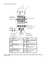
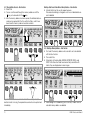
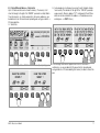
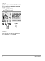
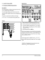
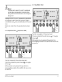
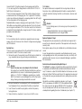
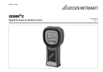
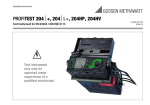
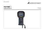
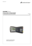
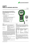
Operating Instructions PROFiTEST®C-GB int. Test Instrument per DIN VDE 0100 3-349-074-03 17/12.14 PROFiTEST®C Measuring and Test Instrument Infrared Interface Interface Adapter (for plug-on instructions see page 4) L1 black L2 (N) blue Control and Display Unit L3 (PE) Test Plug Contact Surface ! Replacement Fuses F1H250V F2H250V Netz Mains 300V CAT III Car ryin gS trap sp Cla 2 Battery Compartment for 4 IEC LR14 Housing Rear Panel Fuse 2 Fuse 1 Jack for External Battery Charger Article No. Z501N 3-Phase Measuring Adapter Article No. Z521A Attention! Removing the Test Plug from the Measuring Adapter Disconnect L1, L2 and L3 from the mains before removing the test plug from the 3-phase measuring adapter. The measuring adapter can only be separated from the test plug with an appropriate tool. Exclusion of Liability When testing systems with RCCBs, the latter may switch off. This may occur even though the test does not normally provide for it. Leakage currents may be present which, in combination with the test current of the test instrument, exceed the shutdown threshold value of the RCCB. PCs which are operated in proximity to such RCCB systems may switch off as a consequence. This may result in inadvertent loss of data. Before conducting the test, precautions should therefore be taken to ensure that all data and programs are adequately saved and the computer should be switched off, if necessary. The manufacturer of the test instrument assumes no liability for any direct or indirect damage to equipment, computers, peripheral equipment or data bases when performing the tests. GMC-I Messtechnik GmbH PROFiTEST®C Control and Display Unit / mp Netz La E P PE i ns Ma Netz Mains mp La UL mp La RC F D/ IL p am RCD FI UL The scroll bar indicates which menu function is currently active. Battery Level Display (continuous) LCD The desired menu functions can be displayed with the and keys: Left Switch Contact: Displays Basic Functions, Scrolling from Right to Left LCD Key for the Selection of Basic Functions and Sub-Functions (menu-driven operation) START Toggle Switch Middle Switch Contact: Start Measurement Significance Right Switch Contact: Displays Basic Functions, Scrolling from Left to Right LCD Significance No mains connection N PE L 3-pole mains connection L at the plug is connected to L at the outlet. N PE L N PE L GMC-I Messtechnik GmbH 3-pole mains connection L at the plug is connected to N at the outlet. Error for polarized plug/outlet systems x N PE L 2-pole mains connection or interrupted N conductor L at the plug is connected to L at the outlet. x N PE L 2-pole mains connection or interrupted N conductor L at the plug is connected to N at the outlet. Error for polarized plug/outlet systems x N PE L Error: PE conductor is apparently interrupted. Perform contact test! 3 + LCD after Switching on the Instrument Please proceed as follows if the LCD display is not legible, i.e. too bright or too dark, after switching on the test instrument: 1 Simultaneously press the two right-hand keys to delete the memory which might be faulty. 2 Wait a few seconds to allow the display to be updated. 3 Readjust the contrast if necessary, see page 9. Instructions for the Plug-on of the Accessory Adapter • Interface converter IrDa-USB (Z501J) ➭ Connect the adapter with the IR interface of the test instrument, see drawing on page 2: Insert the guide rail of the adapter in the opening provided on top of the tester so that the adapter is located in the middle of the housing, resting on the two rubber cushions. Then push the adapter down to ensure that it is safely fastened. 4 PC software WinProfi for communication with PROFiTEST®C The free PC starter software WinProfi* is used for communication with your PROFiTEST®C test instrument. WinProfi is available on our homepage with the following content and functions: • up-to-date test instrument software – for loading another language – for loading software version updates, • Exchange of measured data between test instrument and PC The following interface adapter is required for communication between test instrument and PC: – IrDa-USB Converter (Z501J): IrDa (tester) – USB (PC) Up-to-date PC software (free of charge starter or demo software for data management, report and list generation) is available from our homepage for download. * WinProfi can be used currently up to Windows 7 (32 bit) Data Backup Measurement data and electrical circuit assignments can be safely stored in a RAM as long as the associated battery supplies the required voltage. We advise you to regularly transmit your stored data to a PC in order to prevent potential loss of data in the test instrument. We assume no responsibility for any data loss. For data processing and management we recommend the following PC software programs: • • • PC.doc-WORD™/EXCEL™ (report and list generation) PC.doc-ACCESS™ (test data management) ELEKTROmanager/PROTOKOLLmanager for PROFiTEST® ... GMC-I Messtechnik GmbH Contents Page 1 Applications .................................................................................... 6 2 Safety Features and Precautions .................................................... 6 3 Initial Start-Up ................................................................................ 7 3.1 3.2 3.3 3.4 3.5 Switching the Instrument on and Testing the Batteries .......................................7 Installing and Replacing Batteries .....................................................................7 User Guide in a Different Language ..................................................................7 Selecting a Menu and Configuring Basic Settings .............................................8 Downloading a Software Update, Managing Report Data ..................................10 4 General Operation ......................................................................... 13 4.1 4.1.1 4.2 4.3 4.4 4.4.1 4.5 4.5.1 4.5.2 4.5.3 4.6 4.7 Connecting the Instrument .............................................................................13 Checking Earthing Contact Outlets for Correct Connection ...............................13 Automatic Settings, Monitoring and Shutdown ................................................13 Measurement Value Display ...........................................................................14 Database Functions .......................................................................................14 Creating a Data Record – Data Function .........................................................14 Saving Measurement Values – STORE Functions ............................................15 Querying Data Records – View Function .........................................................16 Deleting a Memory Address – Data Function ..................................................16 Delete All Memory Addresses – Data Function ................................................17 Online Help ...................................................................................................18 Print Function ...............................................................................................18 5 Measuring Line Voltage, Frequency, Phase Angle and Phase Sequence .................................................................... 19 5.1 5.2 5.3 2-Pole Connection with Test Plug ..................................................................19 3-Pole Connection with Test Plug and 3-Phase Measuring Adapter (accessory) ............ 19 Voltage Measurement ...................................................................................19 6 Testing RCDs ................................................................................ 20 6.1 Measuring Contact Voltage (in relation to nominal residual current) with 1/3 Nominal Residual Current ..................................................................20 Measuring Contact Voltage and Trip Test with Nominal Residual Current ..........21 Special Tests for Systems and RCCBs ............................................................22 Testing Systems and RCCBs with Rising Residual Current ...............................22 Testing RCCBs with 5 Times IN (10 mA, 30 mA and 100 mA) ........................23 Testing RCCBs with 150 mA ..........................................................................23 RCCB Non-Trip Test with 50% IN for 2 Seconds Prior to Actual Tripping ........24 Testing Special RCCBs ..................................................................................24 6.2 6.3 6.3.1 6.3.2 6.3.3 6.3.4 6.4 GMC-I Messtechnik GmbH Contents Page 6.4.1 Systems with Selective RCCBs ...................................................................... 24 6.4.2 Type G RCCBs .............................................................................................. 25 7 Testing Breaking Conditions for Overcurrent Protective Devices, Measuring Loop Impedance and Calculating Short-Circuit Current (ZLoop function) ........................ 26 7.1 7.2 Measuring with Negative or Positive Half-Wave .............................................. 27 Measuring Loop Impedance with a 15 mA Test Current Without Tripping RCCBs ................................................................................ 27 Evaluating the Measurement Values ............................................................... 28 Measuring Line Impedance ........................................................................... 28 7.3 7.4 8 Earthing Resistance (RE function) ................................................. 29 8.1 8.2 8.3 Performing Measurements ............................................................................ 29 Setting Limit Values ...................................................................................... 30 Evaluating the Measurement Values ............................................................... 30 9 Characteristic Values ................................................................... 31 9.1 Lamp Functions ........................................................................................... 33 10 11 List of Abbreviations and their Meanings ..................................... 33 Appendix ....................................................................................... 34 11.1 Table of Loop Impedance Values .................................................................. 34 11.2 Table of Earthing Resistance Values .............................................................. 34 11.3 Table of Minimum Display Values for Short-Circuit Current for the Determination of Current Ratings for Various Fuses and Circuit Breakers for Systems with a Nominal Voltage of UN=230/400 V ................................... 35 12 Maintenance ................................................................................. 36 12.1 12.2 12.3 12.4 12.5 Self-Test ..................................................................................................... 36 Battery Operation .......................................................................................... 36 Fuses ........................................................................................................... 37 Housing ....................................................................................................... 37 Recalibration ................................................................................................ 38 13 Repair and Replacement Parts Service, Calibration Center and Rental Instrument Service ....................... 38 Product Support ............................................................................ 39 14 5 1 Applications The PROFiTEST®C measuring and test instrument allows for rapid and efficient testing of protective measures in accordance with DIN VDE 0100, ÖVE-EN 1 (Austria) and NIV/NN SEV 1000:2010 (Switzerland), as well as other country-specific regulations. The microprocessor controlled device complies with regulations set forth in IEC 61557/EN 61557/VDE 0413. Part 1: General requirements Part 3: Loop resistance measuring instruments Part 6: RCDs in TT and TN systems Part 7: Phase sequence indicators The test instrument is especially suited for: • Set-up • Initial start-up • Periodic testing • Troubleshooting in electrical systems All of the values required for approval reports (e.g. for ZVEH) can be measured with a test set consisting of the PROFiTEST®C and the METRISOC. Measurement values can be transmitted to a PC, and printed out or archived with the infrared data interface which has been integrated into the PROFiTEST®C. This is very important, especially where product liability is concerned. The applications range of the PROFiTEST®C includes all alternating and 3-phase current systems with 230 V line voltage and 162/3 Hz, 50 Hz and 60 Hz line frequencies. The following can be measured and tested with the PROFiTEST®C: • Voltage • Frequency • Phase sequence • Loop impedance • RCDs • Earthing resistance Seal of Approval 2 Safety Features and Precautions The PROFiTEST®C electronic measuring and test instrument has been manufactured and tested in accordance with safety regulations IEC/ EN 61010-1/VDE 0411-1 and EN 61557. If used for its intended purpose, the safety of the operator and the instrument are assured. Read the operating instructions carefully and thoroughly before using your instrument, and observe all instructions included therein. Make sure that the operating instructions are available to all users of the instrument. Tests may only be performed under the supervision of a qualified electrician. The user must be instructed by a qualified electrician concerning performance and evaluation of the test. Note Manufacturers and importers of electrical medical devices must provide documentation for the performance of maintenance by trained personnel. The measuring and test instrument may not be used: • If the battery compartment cover has been removed • If external damage is apparent • With damaged connector cables and measuring adapters • If it no longer functions flawlessly • After excessive stress due to transport • After lengthy periods of storage under unfavorable conditions (e.g. humidity, dust, extreme temperatures) Meanings of Symbols on the Instrument Warning concerning a point of danger ! (Attention: observe documentation!) Protection class II device CAT III Measuring category III device – 6 9 V DC charging socket for NA102 charging adapter (article no. Z501N) GMC-I Messtechnik GmbH 3 Initial Start-Up 3.1 Switching the Instrument on and Testing the Batteries 3.2 Installing and Replacing Batteries New batteries must be installed before initial start-up, or when only one solid segment remains in the battery symbol. The contents of the memory remain intact during battery replacement (back-up time: approximately 5 to 10 minutes). ! START The instrument can be switched on by pressing any key. Five battery symbols ranging from depleted to fully charged continuously indicate the current battery level in the main menu. Four 1.5 V baby cells in accordance with IEC LR14 are required for operation of the PROFiTEST®C. Use alkaline-manganese batteries only. Rechargeable NiCd or NiMH batteries may be used as well. Be absolutely sure to refer to chapter 12.2, page 36, regarding the charging cycle and the charging adapter. Always replace the batteries in complete sets. Dispose of batteries in an environmentally sound fashion. ➭ Loosen the two slotted screws at the battery compartment cover on the housing rear panel and remove the cover. ➭ Insert four 1.5 V baby cells making certain the they are poled in accordance with the symbols. Insert the two batteries which are half covered by the housing first. ➭ Replace the cover and retighten the screws. ! + If the above message appears during initial start-up – non-defined data in memory – the contents of the memory must be entirely deleted. GMC-I Messtechnik GmbH Attention! The instrument must be disconnected from the measuring circuit (mains) at all poles before the battery compartment is opened. Pull the test plug! Attention! The instrument may not be operated if the battery compartment cover has not been installed and properly tightened! 3.3 User Guide in a Different Language By performing a software update it is possible to load another language for the user guide than the one included in the scope of supplies. Any language currently available is proposed for choice when WinProfi is being installed, see chapter 3.5. 7 3.4 Selecting a Menu and Configuring Basic Settings ➭ Activate the setup key. ➭ Press the default key: on ✓ Settings such as IN, half-waves etc., as well as Ton (= 20 sec.) are reset to the default settings when the instrument is switched on. off ✓ The last used settings remains when the instrument is switched on. ➭ Exit the setup menu by pressing the key. Setting On-Time, Manual Shutdown START Press the or the key in order to display the desired measuring function, the desired device settings or the database functions. Default Settings – Last Used Settings A selection can be made here as to whether the menus will be displayed according to the default settings, or if the last opened menus should be displayed. ➭ Activate the setup key. ➭ Press the Ton key and then the 10sec, 20sec, 30sec or 60sec key depend- ➭ ing upon the desired duration after which the test instrument should switch off automatically. The “>>>>>” setting indicates that automatic shutdown will occur. The selected setting has a substantial influence on battery service life. Exit the setup menu by pressing the key. The instrument can be switched off manually by simultaneously activating the two outermost softkeys. 8 GMC-I Messtechnik GmbH Setting the Clock Background Illumination and Contrast LCD Illumination off on low Contrast high ➭ Activate the Display key. ➭ In order to extend battery service life, display illumination can be switched off entirely. Press the corresponding softkey to this end. If LCD illumination is activated (= ON), it is automatically switched off several seconds after the last key has been activated in order to extend battery service life. As soon as a key is activated again, illumination is switched back on. ➭ Contrast can be optimized with the two keys at the far right. ➭ The setup menu is exited by pressing the START key, and the selected settings become effective. GMC-I Messtechnik GmbH ➭ Activate the Time key. ➭ The cursor appears at the first digit in the date. Enter the desired ➭ ➭ numeral with one of the softkeys. Numerals which do not appear can be displayed with the help of the or the key. Each time a numeral is selected, the cursor moves to the next position to the right. Date and time are saved as soon as the last numeral has been entered. The setup menu is exited by pressing the START key, and the selected settings become effective. 9 3.5 Downloading a Software Update, Managing Report Data If you require an updated test instrument software, it can be downloaded with the help of WinProfi* PC software. The data file with the desired software version is transmitted to the test instrument via the serial interface. The previously installed language is overwritten. Note This software includes all of the functions required for communications between the PROFiTEST®C and the PC. A description of the program is included in the online user’s manual which can be accessed from WinProfi. A Install WinProfi to the PC and Start the Program ➭ Download the WinProfi software from our homepage: http://www.gossenmetrawatt.com ( Products Software Software for Testers WinProfi) ➭ Unzip the zip file „winprofi.zip“. ➭ Install the software on your PC by executing file Setup_WinProfi_Vx.xx.exe. ➭ Select the desired language for the WinProfi software and for the user interface of the test instrument. ➭ Follow the instructions which appear at the monitor. The program is added to your start menu after installation. ➭ Establish a c onnection between your PC and the PROFiTEST®C test instrument by using the IrDa-USB converter. ➭ Start WinProfi. ➭ Switch on the test instrument. ➭ Set the on-time period of the PROFiTEST®C to „>>>>>“ to give you enough time for adjusting the settings in WinProfi before the test instrument switches off again automatically, see chapter 3.4. Display or print out online user’s manual The online manual contains information concerning the software which is not included in these operating instructions. WinProfi Software * 10 WinProfi can be used currently up to Windows 7 (32 bit) GMC-I Messtechnik GmbH B Prerequisites for Software Update or Data Exchange ➭ Find the interface to which the PROFiTEST®C is connected. C Transmission of a Software Update to the Test Instrument ➭ PC: Select the Update All function from the Update menu. Follow the instructions which appear at the monitor. Depending upon the utilized PC, transmission takes from 1 to 2 minutes. Note Always start this function first, before performing an update or changing report templates. After starting this function, WinProfi loads the report files specifically necessary for the connected instrument. Due to the fact that WinProfi has been created for use with several types of test instruments, incorrect test reports may otherwise be loaded, or erroneous options may be made available. The NETZ/MAINS LED of the PROFiTEST®C test instrument lights up green and indicates that the instrument is ready to receive data. If the PC and the test instrument are correctly synchronized, the same LED lights up yellow. During programming sequences, the UL and RCD/FI LEDs light up red and the NETZ/MAINS LED lights up yellow in alternating order. Upon completion of data transmission, the NETZ/MAINS LED briefly lights up green, afterwards all LEDs go out. The message „Transmission done“ appears on the computer screen. ➭ Query information regarding current software version. ! GMC-I Messtechnik GmbH Attention! The instrument may not, under any circumstances, be switched off during transmission, nor may the connection between the instrument and the PC be interrupted! 11 D Managing Report Data ➭ Establish a connection between your PC and the PROFiTEST®C test instrument by using the IrDa-USB converter. ➭ Start WinProfi. ➭ Switch on the test instrument. ➭ Set the on-time period of the PROFiTEST®C to „>>>>>“ to give you enough time for adjusting the settings in WinProfi before the test instrument switches off again automatically, see chapter 3.4. • Send or receive a data file • • Edit or transmit report templates Print data 1 2 3 6 5 4 12 GMC-I Messtechnik GmbH 4 General Operation 4.1 Connecting the Instrument Connect the instrument to the mains with the test plug if the system to be tested is equipped with earthing contact outlets. Voltage between phase L and protective earth PE may not exceed 253 V! Poling at the plug can be ignored. The instrument determines the positions of phase L and neutral N, and automatically reverses poles if necessary. This does not apply to the following measurements, in order to allow for conscious determination of poling at the plug: – Voltage measurement in switch position UL-PE – Phase sequence measurement The position of phase L is identified on the plug. If measurements are take at 3-phase outlets, at distribution cabinets or at permanent connections, use the 3-phase measuring adapter (see page 2), and attach it to the test plug. 4.1.1 Checking Earthing Contact Outlets for Correct Connection Checking earthing contact outlets for correct connection prior to protective measures testing is simplified with the error recognition system integrated in to the test instrument. The instrument displays faulty connections as follows: • Impermissible line voltage (< 170 V or > 253 V): The NETZ/MAINS lamp blinks red and the measuring function is disabled. • Protective conductor not connected, or potential to earth 100 V at > 45 Hz: When contact is made with the contact surface, the PE lamp lights up red. Measurement is not disabled by the illuminated lamp. • Neutral conductor N is not connected (2-pole connection): The NETZ/MAINS lamp blinks green. See “Lamp Functions” on page 33. In countries with polarized electrical outlets (Great Britain, France, Switzerland, Czech republic etc.), it is advantageous to be able to recognize at first glance whether or not L and N have been correctly connected to the outlet, see table on page 3. To date, it has been necessary to initialize the UL-PE voltage measuring function to this end. As of software version AI, GMC-I Messtechnik GmbH symbols are already displayed in the test instrument’s start menu which provide clear-cut information regarding connection of the outlet to the mains. ! Attention! Reversal of N and PE in TN systems cannot be recognized and is not indicated. Reversal of N and PE in electrical systems equipped with RCCBs can be detected by means of loop impedance measurement. The RCCB is not tripped during measurement. 4.2 Automatic Settings, Monitoring and Shutdown The PROFiTEST®C makes appropriate settings for all of the operating conditions it is able to determine on its own. It tests voltage and frequency at the electrical system. Line voltage fluctuations have no influence on measurement results. The contact voltage which is generated by the instrument is monitored during each measurement. If contact voltage exceeds the 50 V limit value, the measurement is interrupted immediately. The UL amp lights up red. If battery voltage drops to below 4.6 V, the instrument cannot be switched on, or it is immediately switched off. Measurement is interrupted automatically, or the measuring sequence is disabled (except for voltage measuring ranges and phase sequence measurement): • If impermissible line voltages occur (< 170 V, > 253 V) during measurements, for which line voltage is required • If excessive temperatures prevail within the instrument Impermissible temperatures usually do not occur until after approximately 50 measuring sequences have been performed once every 5 seconds when the ZLoop function has been selected. If an attempt is made to start a new measuring sequence, an appropriate message appears at the LCD. The instrument switches itself off automatically, at the earliest after the current (automatic) measuring sequence has been completed, and after the predefined on-time has elapsed (see chapter 3.4). On-time is reset to the duration selected in the setup menu each time a key is activated. 13 4.3 Measurement Value Display The following can be displayed at the LCD: • Measurement values as abbreviations and units of measure • The selected function • Error messages When automatic measuring sequences are used, the measurement values are displayed in digital format until the next measuring sequence is started, or until the instrument switches itself off automatically. If the measuring range upper value is exceeded, the upper value is displayed and is preceded with the larger than symbol “>” in order to indicate over-ranging. 4.4 Database Functions The displayed measurement data for each measurement can be saved to an internal database, either with or without comment. A data record must be created and allocated to a specific memory address in order to be able to assign the individual measurement values to different buildings, distribution cabinets and measuring circuits. 4.4.1 Creating a Data Record – Data Function ➭ Select data. ➭ With the help of the softkeys, entries can be made to the BUILDING, DISTRIBUTOR, RCD No., and CIRCUIT fields one after the other, and a designation can be entered for the electrical circuit. Entering Data: Display the desired alphanumeric character by pressing the or the key, and then select the character with the corresponding softkey. Control characters can be displayed in the same way and have the following meanings: Move cursor to the left (without deleting data) Move cursor to the right (without deleting data) Same function as the START key After each character is selected, the cursor moves one position to the right. If or the START key is activated (press at center), the cursor moves to the next entry field. After the fields BUILDING, DISTRIBUTOR, RCD No., and CIRCUIT have been completed, and after acknowledgement has been confirmed with the softkey, the data fields are displayed as inverse images. After the softkey has been activated once again, a designation for the selected electrical circuit can be entered. ➭ First create the desired memory address with the help of the softkeys. After acknowledging with the START key (press at center), the cursor appears at the first data entry position (BUILDING). 14 Note These entries are required by the PC software in order to enter measurement values into the database, and to generate reports with this information automatically. GMC-I Messtechnik GmbH 4.5 Saving Measurement Values – STORE Functions ➭ Start the respective measurement. The store key is displayed after the ➭ ➭ measurement instead of the INFO key. The store key is not displayed until after a given amount of time has elapsed for measurements which are performed without the START key. For example, the store key is not displayed until after a given amount of time after voltage measurements so that the operator can first query the help text with the INFO key. The displayed measurement values are stored to the currently selected database memory address by briefly acknowledging with the STORE key. The key is briefly displayed as an inverse image during storage to memory. Pressing and holding the STORE key allows for the entry of a comment, and storage of the current measurement. Entering a comment: Display the desired alphanumeric character with the or the key and select the desired character with the corresponding softkey. Control characters are displayed in the same way and have the following meanings: reverse and delete, same as the START key After the character has been selected, the cursor moves one position to the right. Already entered characters can be deleted in reverse by pressing and holding any softkey (except for ). After entry of up to 15 characters, save the measurement values and the comment by acknowledging with the START key (press at center) . The following message appears: “Saving data”. Selecting Values to be Saved to Memory for the Generation of Reports Any number of values can be saved to memory for each electrical circuit. Consecutive number are automatically assigned to these values. Since, as a rule, only the worst value, or only a single value is required for reports, this value is determined as follows by the PC software (e.g. PS3). Measuring Function UL-PE, UL-N, UN-PE, U3~, f IN UIN RE tA I UL Isc ZLoop Values Used for Reports First measured value First measured value Largest measured value Only the value identified with the ! symbol Largest measured value First measured value First measured value Smallest measured value The value associated with the smallest Ik value START GMC-I Messtechnik GmbH 15 4.5.1 Querying Data Records – View Function ➭ Select View. ➭ You can scroll forward through the memory addresses with the key, or backwards with the key. ➭ After the memory address has been opened, the individual data records can be queried with the Prev. and Next softkeys, which have been stored to memory under consecutive numbers. Deleting a Data Record from within a Memory Address – View Function ➭ Activate the Del key. No security request appears. Data record numbering is changed as soon as an individual data record is deleted. 4.5.2 Deleting a Memory Address – Data Function ➭ First select the memory address whose contents are to be deleted START with the View function. ➭ Then select Data. ➭ Enter blanks to the data fields BUILDING, DISTRIBUTOR, RCD No. and CIRCUIT. After these four fields have been entirely overwritten with blanks, they are displayed as inverse images. START If you discover that a measurement value for the currently selected electrical circuit is missing, the required measurement can be performed immediately. 16 ➭ Acknowledge with the START key (press at center). All data from the selected memory address are deleted. GMC-I Messtechnik GmbH 4.5.3 Delete All Memory Addresses – Data Function Up to 250 data records can be stored to memory. The memory is full when the triangle to the right of the “MEMORY:” parameter is entirely filled in. The entire memory, i.e. all data records from all memory addresses, can be deleted at once. We recommend uploading and saving your data to a PC before deletion. ➭ Select Data. ➭ Acknowledge by simultaneously pressing O and K to delete all data from memory. The indicator to the right of the “SPEICHER:” parameter appears empty. Memory address “001” is displayed at the left. New data can now be entered for this address, or the database can be exited (press or START 9 times). + 3 times ➭ Enter memory address “000”. An additional security request appears. If the message shown above appears when the test instrument is switched on, you are provided with the opportunity of uploading and saving all data to a PC before deleting the memory in order to correct the error. + GMC-I Messtechnik GmbH 17 4.6 Online Help Appropriate online help texts can be displayed at the LCD for each of the basic functions and sub-functions, after the respective function has been selected in the corresponding menu ➭ Press the i key to query online help. Press any key to exit the help function. 4.7 Print Function Functions whose symbols appear in gray or which are displayed faintly, will not be available until after the next software update. 18 GMC-I Messtechnik GmbH 5 Measuring Line Voltage, Frequency, Phase Angle and Phase Sequence 5.1 2-Pole Connection with Test Plug L1 5.3 Voltage Measurement Voltage measurement between L and PE, N and PE, L and N or phase sequence measurement with line-to-line voltage, phase angle and phase sequence starts automatically after selection of the measuring function. Voltage and frequency overflow is displayed with the “---” symbol. Voltage Between L and PE, and Line Frequency L2 L3 N UN/fN PE RF Observe correct poling at the plug for the above measurement! 5.2 3-Pole Connection with Test Plug and 3-Phase Measuring Adapter (accessory) Voltage Between N and PE, and Between L and N L1 L2 UN-PE L3 N PE Phase Sequence Measurement RF Black Blue U3~ GMC-I Messtechnik GmbH 19 6 Testing RCDs 6.1 Testing RCDs includes visual inspection, testing and measurement. Use the PROFiTEST®C for testing and measurement. Measuring Method According to DIN VDE 0100 it must be substantiated that: – Contact voltage which occurs at nominal residual current does not exceed the maximum allowable value for the system. – The RCCBs are tripped within 400 ms at nominal residual current (1000 ms for selective RCCBs). Measurement is performed by the instrument with a current having a value of less than 1/3 nominal residual current in order to determine contact voltage UIN at nominal residual current. This prevents the RCCB from being tripped. This measuring method offers the special advantage of being able to test contact voltage at any electrical outlet quickly and easily without tripping the RCCB. The usual, cumbersome measuring methods for testing the effectiveness of RCDs at one measuring point, and having to substantiate that all of the other system components which require protection are reliably connected to this measuring point via the PE conductor at low resistance values are a thing of the past. Connection L1 L2 RCD L3 N PE RF 20 RE Measuring Contact Voltage (in relation to nominal residual current) with 1/3 Nominal Residual Current START ➭ Select contact voltage measurement with the UIN/tT key. ➭ Set nominal residual current for the utilized RCCB with the IN key. ➭ If the contact voltage limit value deviates from 50 V, or if a selective RCCB is involved, the corresponding value must first be selected by activating the TYPE key. ➭ Start the measurement by briefly acknowledging with the START key. Contact voltage UIN I (in relation to nominal residual current) and calculated earthing resistance RE are displayed at the LCD. Note Interference voltages at the protective conductor PE or at the earth electrode have no influence on measuring results, as long as they are less than 25 V. Interference voltages can be measured by performing a voltage measurement with the test plug. If biasing current with relatively large values is present within the system, or if the selected test current was too large for the RCCB, tripping may occur during testing. In such cases, the following message appears at the display “Stop! No current. Check breaker”. GMC-I Messtechnik GmbH If contact voltage UIN measured with 1/3 nominal residual current and projected to IN by means of calculation is greater than 50 V (> 25 V), the UL lamp lights up red. If contact voltage UIN exceeds 50 V during testing, safety shutdown ensues. Contact voltages of up to 99.9 V are displayed. Overflow is indicated for larger values. Limit Values for Permissible Continuous Contact Voltage The limit for permissible continuous contact voltage is UL = 50 V for alternating voltage (international agreement). Lower voltages are required in special applications (e.g. medical applications UL = 25 V). 6.2 Measuring Contact Voltage and Trip Test with Nominal Residual Current After contact voltage has been measured, testing can be performed to ascertain whether or not the RCCB is tripped within 400 ms, or 1000 ms, at nominal residual current. If the RCCB is tripped at nominal residual current, the NETZ/MAINS lamp blinks red (mains voltage has been interrupted), and contact voltage UIN and time to trip tT appear at the display. If the RCCB is not tripped at nominal residual current, the RCD/FI lamp lights up red. The trip test is only required at one measuring point for each RCCB. ! Attention! If contact voltage is too great, or if the RCCB is not tripped, the system must be repaired (e.g. earthing resistance is too high, defective RCCB etc.)! The trip test must be performed at one of the three phases (L1, L2 and L3) in order to assure flawless functioning of the RCD. Note Earthing resistance is automatically measured during the trip test. However, the accuracy of the measured value depends to a great extent upon the utilized measuring current. For example, the measured value is relatively inaccurate with measuring currents of 10 mA and 30 mA, because measurement resolution is reduced due to minimal current. Better results can be obtained with the RE function (see chapter 8, page 29). START ➭ Press the start START key in order to measure UIN, and continue to Note Measurement Value Processing with PC Software (e.g. PS3) Only one RE measurement value is entered to some of the report forms. In order to assure that the PC software enters the desired value, enter the ! symbol as the first character in the comment line after the value has been saved to memory (see chapter 4.5), for example: !Foundation earth. hold it depressed even after the measurement value has been displayed. The trip test is started automatically after contact voltage UIN has been measured. GMC-I Messtechnik GmbH 21 6.3 Measuring Sequence Special Tests for Systems and RCCBs 6.3.1 Testing Systems and RCCBs with Rising Residual Current Measuring Method The instrument generates a continuously rising residual current IN (from 0.3 to 1.3) within the system for RCD testing. The contact voltage and tripping current values which prevail at the moment the RCCB is tripped are stored to memory and displayed by the instrument. The operator can select between two different contact voltages, UL = 25 V or UL = 50 V, for measurement with rising residual current. START Connection L1 L2 L3 N PE RF ➭ Select measurement with rising residual current with the I key. ➭ Set nominal residual current for the utilized RCCB with the IN key. ➭ If the contact voltage limit value deviates from 50 V, or if a selective RCCB is involved, the corresponding value must first be selected by activating the TYPE key. ➭ Start the measurement with the START key. After the measuring sequence has been started, test current generated by the instrument rises starting at a value of 0.3 nominal residual current until the RCCB is tripped. This can be observed at the sine symbol. Tripping current I is displayed at the LCD. If contact voltage reaches the selected limit value (UL = 50 V or 25 V) before the RCCB is tripped, safety shutdown ensues. The UL lamp lights up red. If the RCCB is not tripped before the rising current reaches nominal residual current IN, the RCD/FI lamp lights up red. 22 GMC-I Messtechnik GmbH 6.3.3 Testing RCCBs with 150 mA ! Attention! If a biasing current is present in the system it is superimposed onto the residual current generated by the instrument during testing and influences measured values for contact voltage and tripping current. According to DIN VDE 0100, part 610, measurement may be performed with rising current in order to evaluate RCDs, and contact voltage for nominal residual current IN may by calculated based upon the measured values. The faster and simpler method is thus generally preferred (see chapter 6.1). 6.3.2 Testing RCCBs with 5 Times IN (10 mA, 30 mA and 100 mA) Time to trip is measured with a 150 mA constant current. The test can be started with the positive half-wave „ “, or the negative half-wave “ ”. Both measurements must be performed. The longer time to trip is decisive regarding the condition of the tested RCCB. Both values must be less than 40 ms. Time to trip is measured with 5 times nominal residual current. The test can be started with the positive half-wave „ “, or the negative half-wave “ ”. Both measurements must be performed. The longer time to trip is decisive regarding the condition of the tested RCCB. Both values must be less than 40 ms. GMC-I Messtechnik GmbH 23 6.3.4 RCCB Non-Trip Test with 50% IN for 2 Seconds Prior to Actual Tripping In addition to the 30%-U IN measurement and the 100% IN trip test, a non-trip test with 50% IN and a duration of 2 seconds can be performed if desired. If the “½ IN ON” option has been selected, an appropriate icon appears at the display. The icon is highlighted during the 50% test in order to indicate execution. If an RCCB is tripped during the 50% test, testing is interrupted and an appropriate message appears at the display. ½ IN on or off can be selected in the vIN menu. 6.4 Testing Special RCCBs 6.4.1 Systems with Selective RCCBs Selective RCCBs are used in systems equipped with two series connected RCCBs which are not triggered simultaneously in the event of an error. These RCCBs have a time delayed tripping response and are identified with the symbol S . Measuring Method The same measuring method is used as is the case for normal RCCBs (see chapter 6.1, page 20, and 6.3.1, page 22). If selective RCCBs are used, earthing resistance may only be half as great as is the case for normal RCCBs. For this reason, the contact voltage displayed at the instrument is twice the actual measured value. Display in the event of premature tripping of the RCCB The selection as to whether or not the non-trip test is included in the measurement remains unchanged after switching the instrument off. ➭ Select the limit value for allowable contact voltage, UL50V S or UL25V S , in the respective TYPE sub-menu. 24 GMC-I Messtechnik GmbH Trip Test ➭ Press the START key. The RCCB is tripped. The clock appears at the display, followed by time to trip tT and earthing resistance RE. 6.4.2 Type G RCCBs In addition to common selective RCCBs, the special characteristics of the type G RCCB can also be tested with the PROFiTEST®C test instrument. ➭ First set the instrument to the indicated nominal residual current IN. ➭ Measure contact voltage and time to trip as you would for normal RCCBs. START ➭ Then select 5·I Note Selective RCCBs have a delayed breaking response. Breaking response is influenced for a brief period (up to 30 s) by pre-loading during measurement. In order to eliminated pre-loading caused by the measurement of contact voltage, a pretest waiting period is required before the trip test can be started. After the measuring sequence has been started (trip test), a clock appears at the display. Time to trip values of up to 1000 ms are permissible. GMC-I Messtechnik GmbH in the TYPE sub-menu and perform the trip test with the positive half-wave. Repeat the trip test with the negative half-wave after selecting 5·I . The longer time to trip is decisive regarding the condition of the tested RCCB. In both cases, time to trip must lie within a range of 10 ms (minimum delay time for the type G RCCB!) to 40 ms. Type G RCCBs with different nominal residual current values must be tested under menu item IN with the function selector switch in the appropriate setting. Note Menu selection S for selective RCCBs is not suitable for type G RCCBs. 25 7 Testing Breaking Conditions for Overcurrent Protective Devices, Measuring Loop Impedance and Calculating Short-Circuit Current (ZLoop function) Connection L1 Testing overcurrent protective devices includes visual inspection and measurement. Use the PROFiTEST®C for measurement. L2 Measuring Method Loop impedance ZLoop is measured and short circuit current Isc is calculated in order to determine whether or not breaking conditions are fulfilled by the overcurrent protective device. Loop impedance is the resistance of the current loop (power distribution station – phase conductor – protective conductor) when a short-circuit to frame occurs (conductive connection between phase conductor and protective conductor). The loop resistance value determines the magnitude of short-circuit current. Short-circuit current Isc may not drop to below the value set forth in DIN VDE 0100, in order to assure that the system’s protective device (fuse, circuit breaker) breaks in a reliable fashion. For this reason, measured loop impedance must be less than the maximum allowable value. Tables including allowable display values for loop impedance, as well as minimum display values for short-circuit current for various fuse and breaker current ratings can be found in chapter 11 starting on page 34. Maximum instrument error is taken into consideration in these tables (see also chapter 7.3). In order to measure loop impedance ZLoop, the instrument uses a test current of 740 mA and a test duration of approximately 400 ms regardless of line voltage and line frequency. If dangerous contact voltage occurs during this measurement (> 50 V), safety shutdown ensues. The measuring and test instrument calculates short-circuit current Isc based upon measured loop impedance ZLoop and line voltage. Short-circuit current is based upon nominal voltage 230 V (170 V 265 V) or on nominal voltage 120 V (80 170 V). Loop impedance can be measured either with the positive or the negative half-wave with the PROFiTEST®C. By using this measuring method in combination with the PROFiTESTDC-II measuring adapter, loop impedance can be measured in systems equipped with RCCBs without causing them to trip. N 26 L3 PE RF Measurement of loop impedance must be performed from all three phases (L1, L2 and L3) to the protective conductor PE for 3-phase systems in order to assure flawless functioning of the overcurrent protective device. START ➭ Select loop impedance measurement with the ZLoop key. A solid sine ➭ wave should be displayed as the active waveshape. Refer to the next chapter regarding measurements at RCCBs. Start the measurement with the START key. GMC-I Messtechnik GmbH 7.1 Measuring with Negative or Positive Half-Wave Measurement with half-waves allows for the measurement of loop impedance in systems equipped with RCCBs with the help of the PROFiTESTDC-II measuring adapter. Connection L1 L2 RCD L3 7.2 Measuring Loop Impedance with a 15 mA Test Current Without Tripping RCCBs In order to perform measurement of loop impedance with IN 30 mA via RCCBs without causing them to trip, select the “15 mA” item in the loop impedance measurement menu. The menu is shown in figure 1, and figure 2 shows a sample measurement. Measuring resolution for the 15 mA measurement is only 100 m instead of 10 m. The duration of the measurement is extended to 1.6 seconds. The measuring range is from 0.1 to 250 . N PE RF RE Starting the Measurement Use the positive half-wave for the measurement of loop impedance. Loop impedance measurements via RCCBs with IN 10 mA is not possible. START GMC-I Messtechnik GmbH 27 7.3 Evaluating the Measurement Values Maximum allowable loop impedance ZLoop can be determined with the help of the on page 34. These are the maximum values which may be displayed after taking the device’s maximum measuring error into consideration (under normal measuring conditions). Intermediate values can be interpolated. The maximum allowable current rating for the protective device (fuse or breaker) can be determined for a nominal line voltage of 230 V with the help of the Table of Minimum Display Values for Short-Circuit Current on page 35 based upon measured short-circuit current, under consideration of the device’s maximum measuring error (in compliance with DIN VDE 0100, part 610). After measurement has been performed, allowable fuse types can be displayed by pressing the key. The table shows maximum allowable current ratings depending upon fuse type and breaking conditions. Note If ZLoop is greater than 100 , the following error message appears: “defective F1 ...”. No test current can be made available when the following error occurs: resistance too great, fuse defective or earth electrode is not connected. 7.4 Measuring Line Impedance Line impedance can only be measured with the Z521A 3-phase measuring adapter (accessory). Connect terminal L1 (black) from the adapter to the mains phase and terminal L3 (PE) to the mains neutral conductor. Now perform a “loop measurement”. Line impedance (internal system resistance) is displayed as a result of this measurement. In order to assure that the PC software (e.g. PS3) does not recognize this procedure as a ZLoop measurement, but rather as a Zi measurement, enter the ! symbol as the first character in the comment line after the value has been saved to memory (see chapter 4.5, page 15), for example !Outlet 12. 28 GMC-I Messtechnik GmbH 8 Earthing Resistance (RE function) Connections Earthing resistance is the sum of earth electrode dissipation resistance (RD) and resistance of the earth conductor. Earthing resistance is roughly calculated with an “earth electrode loop resistance measurement”. The resistance value RELoop determined with this measuring method includes resistance values for functional earth RF and phase L as well. These two values must be subtracted from the measured value in order to determine earthing resistance. Assuming equal conductor cross-sections (phase L and neutral N), resistance at the phase conductor is half a great as line impedance ZI (phase + neutral). According to DIN VDE 0100, functional earth RF must lie within a range of 0 to 2 . Earthing resistance is calculated with the following equation: 1 – --- R – R R =R B E E Loop 2 I L1 L2 L3 N PE RE RF 8.1 Performing Measurements Automatic Measuring Range Selection When calculating earthing resistance, it is advisable to ignore the resistance value for functional earth RF, because this value is generally unknown. The calculated resistance value thus includes the functional earth resistance value as a safety factor. Line impedance ZI can only be measured with the 3-phase measuring adapter (accessory) in the ZLoop mode. Note Interference voltages at the protective conductor PE or at the earth electrode have no influence on measuring results. They can be measured by performing a voltage measurement with the test plug. If dangerous contact voltage occurs during measurement (> 50 V), the measurement is interrupted and safety shutdown ensues. GMC-I Messtechnik GmbH START 29 Manual Measuring Range Selection Manual measuring range selection is provided for in case earthing resistance needs to be measured in systems which are equipped with RCCBs. The instrument’s test current IT must be taken into consideration in order to prevent undesired tripping of the RCCB. 4..740 mA 740 mA 400 mA 40 mA 4 mA START ➭ Press the RANGE key. ➭ Select the measuring range with a test current which is less than the tripping current of the utilized RCCB. ➭ Start the measurement as described above. Note When manual range selection is used it must be observed that indicated accuracy values are only valid starting at 5% of the upper range limit value (except for 10 range, separate entry for small values). 8.2 Setting Limit Values A limit value can be selected for earthing resistance. If a measurement value exceeds this limit value, the UL LED lights up. 30 ➭ Press the LIMIT key. ➭ First enter the numeral for the hundreds place. Display the desired numeral with the or the key to this end. After a numeral has been selected, the cursor moves one place to the right. After the tens and the units have been entered, the cursor moves to position _ for ohms, or position k for kilo-ohms. The start menu appears after this last entry has been made. 8.3 Evaluating the Measurement Values With the help of the on page 34, maximum resistance display values can be determined which may not be exceeded under consideration of the device’s maximum measuring error in order to avoid exceeding the required earthing resistance. Intermediate values can be interpolated. Note Measurement Value Processing with PC Software (e.g. PS3) Only one RE measurement value is entered to some of the report forms. In order to assure that the PC software enters the desired value, enter the ! symbol as the first character in the comment line after the value has been saved to memory (see chapter 4.5), for example: !Foundation earth. GMC-I Messtechnik GmbH 9 Characteristic Values Function Measured Quantity UL–PE UN–PE UL–PE UN–PE / UL–N f U3~ U3~ Input Impedance / Test Current Nominal Values Intrinsic uncertainty Nominal Range of Use Measuring uncertainty 0.1 V 1V 500 k — (2% of rdg. + 2 d) 108 ... 253 V (4% rdg. + 3 d) 0.1 Hz 1 Hz 0.1 V 1V 500 k — (0.1% of rdg. + 1 d) 15 ... 70 Hz (0.2% rdg. + 1 d) 500 k — (2% of rdg. + 2 d) 108 ... 440 V (4% rdg. + 3 d) +(12.5% of rdg. + 2 d) +(2.5% of rdg. – 2 d) 5 ... 70 V +15% rdg. + 2 d — Calculated Value — 0 ... 99.9 V 0.1 V 0.3 · IN RE / IN = 10 mA 10 ... 9.99 k 3 ... 999 1 k ... 6.40 k 1 ... 999 0.3 ... 99.9 100 ... 640 0.2 ... 99.9 100 ... 380 3.0 ... 13.0 mA 9.0 ... 39.0 mA 30 ... 130 mA 90 ... 390 mA 150 ... 650 mA 0 ... 25.0 V 0 ... 50.0 V 0 ... 99.9 ms 100 ... 999 ms 0 ... 0.49 0.5 ... 9.99 10.0 ... 30.0 0 ... 99.9 100 ... 250 0 ... 0.49 0.5 ... 9.99 10.0 ... 99.9 100 ... 999 1.00 k ... 9.99 k 10 3 10 1 0.3 1 0.2 1 0.3 ... 1.3 · IN RE / IN = 100 mA RE / IN = 300 mA RE / IN = 500 mA I / IN = 10 mA I / IN = 30 mA I / IN = 100 mA I / IN = 300 mA I / IN = 500 mA UI / UL = 25 V UI / UL = 50 V tT (IN/5 · IN) ZLoop ZLoop ZLoop 15 mA RE Resolution UIN RE / IN = 30 mA I Measuring Range (display range) 0 ... 99.9 V 100 ... 300 V (0 ... 600 V) 15.0 ... 99.9 Hz 100 ... 650 Hz 0 ... 99.9 V 100 ... 500 V (0 ... 600 V) RE GMC-I Messtechnik GmbH UN = 120 V UN = 230 V fN = 50 Hz 1 mA 1 mA 1 mA 3.0 ... 13.0 mA 9.0 ... 39.0 mA 30 ... 130 mA 90 ... 390 mA 150 ... 650 mA 0.1 V same as I +(12.5% of rdg. + 2 d) +(2.5% of rdg. – 2 d) 3.0 ... 13.0 mA 9.0 ... 39.0 mA 30 ... 130 mA 90 ... 390 mA 150 ... 650 mA 0 ... 25.0 V 0 ... 50.0 V 1.05 · IN / 5 · IN 3 ms 0 ... 1000 ms 4 ms 5 d (6% of rdg. + 3 d) (6% of rdg. + 3 d) (6% of rdg. + 5 d) (6% of rdg. + 3 d) 5 d (6% of rdg. + 3 d) (4% of rdg. + 3 d) (4% of rdg. + 3 d) (4% of rdg. + 3 d) 0.25 ... 0.49 0.50 ... 9.99 10.0 ... 30.0 0.50 ... 99.9 100 ... 250 0.25 ... 0.49 0.50 ... 9.99 10.0 ... 99.9 100 ...999 1 k ...9.990 k (15% of rdg. + 5 d) (10% of rdg. + 5 d) (10% of rdg. + 5 d) (15% of rdg.+10 d) (10% of rdg.+10 d) (15% of rdg. + 5 d) (10% of rdg. + 5 d) (8% of rdg. + 5 d) (8% of rdg. + 5 d) (8% of rdg. + 5 d) 0.1 mA 0.1 ms 1 ms 10 m 10 m 100 m 100 m 1 10 m 10 m 10 m 100 m 1 UL = 25/50 V IN = 10/30/100/ 300/500 mA 740 mA 15 mA 740 mA 740 mA 400 mA 40 mA 4 mA UN = 120 V UN = 230 V fN = 50 Hz (5% of rdg. + 2 d) (8% rdg. +2 d) +15% rdg.+2 d 31 Reference Conditions Line Voltage Line Frequency Measured Quantity Waveshape Line Impedance Angle Power Supply Ambient Temperature Relative Humidity Finger Contact Nominal Ranges of Use Voltage UN Frequency fN Overall Frequency Range Waveshape Temperature Range Battery Voltage Line Impedance Angle Ambient Conditions Storage Temperature Operating Temperature Relative Humidity Elevation Deployment 32 230 V 0.1% 50 Hz 0.2 Hz sine (deviation between RMS and rectified value 1%) cos = 1 battery: 5.5 V 1% +23 C 2 K 40% ... 60% potential difference to earth potential during testing 120 V 230 V 16 2/3 Hz 50 Hz 60 Hz (108 170 V) (170 ... 253 V) (15.4 ... 18 Hz) (49.5 ... 50.5 Hz) (59.4 ... 60.6 Hz) 15 ... 70 Hz sine 0 C ... + 40 C 4.6 V ... 6.5 V corresponds to cos = 1 ... 0.95 –20 C ... +60 C (without batteries) –10 C ... +50 C max. 75%, no condensation allowed max. 2000 m indoors; outdoors only within the specified ambient conditions Power Supply Batteries Rechargeable batteries Battery Charger (not included) 4 ea. 1.5 V baby cells (4 x C-Size) (alkaline-manganese per IEC LR14) NiCd or NiMH NA 102 (article no. Z501N), 3.5 mm dia. jack plug Charging Time approx. 14 hours Due to minimal charging capacity, fewer measurements can be performed with rechargeable batteries than with normal batteries as a rule. Electrical Safety Safety Class Operating Voltage Test Voltage Measuring Category Fouling Factor Electromagnetic Compatibility (EMC) Fuses at Terminals L and N Overload Capacity UL-PE, UL-N RC, RE, ZLoop Fine-Wire Fuse Protection II per IEC 61010-1/EN 61010-1/ VDE 0411-1 300 V 3.7 kV 50 Hz III 2 IEC 61326/EN 61326 1 ea. type G fuse link F1H250V 5 mm x 20 mm (per IEC 127-2) 600 V continuous 300 V (Limits the number of measurements and idle time. A thermostatic switch prevents execution of the function if overload occurs.) 1 A 10 s, > 2 A fuse blows GMC-I Messtechnik GmbH 10 Data Interface Type infrared interface (SIR/IrDa) bidirectional, half-duplex 9600 baud, 1 start bit, 1 stop bit, 8 data bits, no parity, no handshake max. 10 cm, recommended distance: < 4 cm Format Range Mechanical Design Display Dimensions Weight Protection multiple dot matrix display, 64 x 128 pixels, illuminated 275 mm x 140 mm x 65 mm (without meas. cables) approx. 1.2 kg with batteries housing: IP 52 per DIN VDE 0470 part 1/EN 60529 with pressure compensating diaphragm of microporous ePTFE, non-aging, dia. 8 mm in battery compartment cover Extract from table on the meaning of IP codes IP XY (1st digit X) Protection against foreign object entry IP XY (2nd digit Y) 5 dust protected 2 9.1 Protection against the penetration of water vertically falling drops with enclosure tilted 15 Lamp Functions Lamp Status Measuring Function PE lights up red all Netz Mains lights up green I / RE / ZLoop Netz Mains blinks green I / RE / ZLoop Netz Mains blinks red I / RE / ZLoop UL lights up red RCD/FI lights up red I RE I Function Device on and potential difference 100 V between finger contact and PE (protective contact), frequency: f > 45 Hz 3-pole connection: line voltage approx. 170 V to 253 V, measurement enabled 2-pole connection (e.g. N conductor not connected): line voltage approx. 170 V to 253 V, measurement enabled Line voltage < approx. 170 V or > 253 V, measurement disabled – Contact voltage UIN or UI > 25 V or > 50 V – Safety shutdown has occurred – Limit value for RE exceeded The RCCB was not tripped, or was tripped too late during the trip test List of Abbreviations and their Meanings RCCBs I IN IF PRCD RE Tripping current Nominal residual current Rising test current (fault current) Portable RCD Calculated earthing resistance or earth electrode loop resistance Selective RCCB S SRDC Socket RCD (permanently installed) tT Time to trip UI Contact voltage at the moment of tripping UIN Contact voltage related to nominal residual current IN UL Contact voltage limit value Overcurrent Protective Devices Isc Calculated short-circuit current (at nominal voltage) ZLoop Loop impedance Earthing Functional earthing resistance RF RE Measured earthing resistance RELoop Earth electrode loop resistance Current IM Measuring current IN Nominal current IT Test current Voltage f fN UE UL-L UL-N UL-PE UN U3~ Line voltage frequency Nominal frequency for nominal voltage Earth electrode voltage Voltage between two phases Voltage between L and N Voltage between L and PE Nominal line voltage Highest voltage measured while determining phase sequence The Netz/Mains lamp is not activated for measurement of UL-PE. GMC-I Messtechnik GmbH 33 11 Appendix Tables for determining maximum and minimum display values under consideration of the device’s maximum measuring error. These tables do not apply for the measurement with 15 mA test current! 11.1 Table of Loop Impedance Values 11.2 Table of Earthing Resistance Values ZLoop Limit Value 0.25 0.30 0.35 0.40 0.45 0.50 0.60 0.70 0.80 0.90 1.00 1.50 2.00 2.50 3.00 3.50 4.00 4.50 5.00 6.00 7.00 8.00 9.00 10.00 15.00 20.00 25.00 30.00 34 Max. Display Value 0.18 0.22 0.27 0.31 0.36 0.40 0.50 0.59 0.68 0.77 0.86 1.31 1.77 2.22 2.68 3.13 3.59 4.04 4.50 5.40 6.31 7.22 8.13 9.04 13.1 17.7 22.2 26.8 RE Limit Value 0.25 0.30 0.35 0.40 0.45 0.50 0.60 0.70 0.80 0.90 1.00 1.50 2.00 2.50 3.00 3.50 4.00 4.50 5.00 6.00 7.00 8.00 9.00 10.00 Max. Display Value 0.18 0.22 0.27 0.31 0.36 0.40 0.50 0.59 0.68 0.77 0.86 1.31 1.77 2.22 2.68 3.13 3.59 4.04 4.50 5.40 6.31 7.22 8.13 9.04 Limit Value 10.0 15.0 20.0 25.0 30.0 35.0 40.0 45.0 50.0 60.0 70.0 80.0 90.0 100 150 200 250 300 350 400 450 500 600 700 800 900 Max. Display Value 9.04 13.8 18.4 23.1 27.7 32.3 36.9 41.6 46.2 55.5 64.7 74.0 83.2 92.5 138 184 231 277 323 369 416 462 555 647 740 832 Limit Value 1.00 k 1.50 k 2.00 k 2.50 k 3.00 k 3.50 k 4.00 k 4.50 k 5.00 k 6.00 k 7.00 k 8.00 k 9.00 k 9.99 k Max. Display Value 925 1.38 k 1.84 k 2.31 k 2.77 k 3.23 k 3.69 k 4.16 k 4.62 k 5.55 k 6.47 k 7.40 k 8.32 k 9.25 k GMC-I Messtechnik GmbH 11.3 Table of Minimum Display Values for Short-Circuit Current for the Determination of Current Ratings for Various Fuses and Circuit Breakers for Systems with a Nominal Voltage of UN=230/400 V Low-Voltage Fuses in Accordance with the DIN VDE 0636 Series of Standards Characteristic gL, gG, gM Nominal Current IN [A] 2 3 4 6 8 10 13 16 20 25 32 35 40 50 63 80 100 125 160 Breaking Current, 5 s Limit Value [A] 9.2 14.1 19 27 37 47 56 65 85 110 150 173 190 260 320 440 580 750 930 Min. Display [A] 10 16 22 30 41 52 62 73 95 124 171 199 219 305 381 541 741 1.01 k 1.32 k Breaking Current, 0.4 s Limit Value [A] 16 24 32 47 65 82 98 107 145 180 265 295 310 460 550 Min. Display [A] 18 27 35 52 73 92 110 121 165 207 311 349 368 569 697 with protective Circuit Breaker and Circuit Breaker Characteristic B/E (previously L) Breaking Current, 5 x IN (< 0.2 s / 0.4 s) Limit Value Min. Display [A] [A] 10 11 15 17 20 23 30 33 40 44 50 56 65 73 80 90 100 113 125 142 160 183 175 201 200 231 250 292 315 375 Characteristic C (previously G, U) Breaking Current, 10 x IN(< 0.2 s / 0.4 s) Limit Value Min. Display [A] [A] 20 23 30 33 40 44 60 67 80 90 100 113 130 148 160 183 200 231 250 292 320 381 350 420 400 487 500 625 630 816 Characteristic D Characteristic K Breaking Current, 20 x IN(< 0.2 s / 0.4 s) Limit Value Min. Display [A] [A] 40 44 60 67 80 90 120 136 160 183 200 231 260 305 320 381 400 487 500 625 640 831 700 925 800 1.09 k 1000 1.45 k 1260 1.98 k Breaking Current, 12 x IN(< 0.1 s) Limit Value Min. Display [A] [A] 24 27 36 40 48 53 72 81 96 108 120 136 156 178 192 221 240 280 300 356 384 465 420 514 480 596 600 771 756 1.02 k 960 1.37 k 1200 1.85 k 1440 2.42 k 1920 3.90 k Example Display value 90.4 A ➜ next smallest value for characteristic B circuit breaker from table: 85 A ➜ rated current (IN) for the protective device is max. 16 A. GMC-I Messtechnik GmbH 35 12 Maintenance ➭ Display: Press the Test key after each test pattern has been displayed in order test the display elements. 12.1 Self-Test ➭ Keytest: Perform the key test by pressing each of the softkeys once, and by pressing the start key once in each of its three positions. The keys appear filled in at the key pictograph after they have been tested. Individual tests can be skipped by pressing the Skip key before starting the respective test. These tests are then identified with a horizontal dash, as is also the case for tests which have not been passed. ➭ The self-test is started from the main menu with the Test key. 12.2 Battery Operation When only one solid segment remains in the battery symbol, the batteries must be replaced, or recharged if rechargeable batteries are used. Check the batteries at short, regular intervals or after lengthy periods of storage to make sure no leakage has occurred. If leakage has occurred, the electrolyte must be carefully and completely removed from the instrument with a damp cloth before new batteries are installed. The test has a duration of several minutes. The following information is displayed in the two headers: Type/Cal: Device type / date of last calibration Version: Software version and issue date Self-tests for items Chksum through LED are performed automatically, one after the other, and are checked off or marked with a horizontal dash if they are not passed. Chksum1/2: Status display for internal testing (Each test must be completed with a check mark. If not, the measuring and test instrument may no longer be used. Please contact our service center in this case. Relays: Each relay is switched twice. LEDs: The U and RCD/FI lamps each blink twice in red, and the Netz/Mains lamps blinks twice in green and twice in red. The PE lamp cannot be tested automatically! As soon as the tests in the left-hand column have been completed, the following tests must be started manually. ➭ Illum: Press the Test key twice in order to activate and deactivate display illumination. 36 Note Prior to lengthy periods of rest (e.g. holiday), we recommend removing the (rechargeable) batteries. This helps to prevent excessive depletion or leakage of batteries, which, under unfavourable circumstances, may cause damage to the instrument. Charging the Batteries ! Attention! Use only the NA102 battery charger (article no. Z501N) with safe electrical isolation and a nominal secondary voltage of 9 V DC to recharge the batteries. Before connecting the battery charger to the charging socket at the device, make sure of the following points: – Rechargeable batteries have been installed (not normal batteries). – The instrument has been disconnected from the measuring circuit at all poles. – The voltage selector at the charger has been set to 9 V. GMC-I Messtechnik GmbH Connect the NA 102 battery charger to the charging socket with the 3.5 mm jack plug. Set the voltage selector switch at the NA 102 to 9 V. Switch the test instrument on. The test instrument recognizes the fact that a battery charger has been connected and starts the charging cycle. The 5 segments of the battery symbol are continuously displayed in a sweeping pattern from left to right for the entire duration of the charging cycle. Depleted batteries require a charging cycle of approximately 14 hours. If the batteries are exhausted to a great enough extent, the test instrument can no longer be switched on. If this is the case, leave the test instrument connected to the activated battery charger for about 30 minutes, and then proceed as described above. 12.3 Fuses If a fuse has blown due to an overload, an appropriate error message appears at the LCD. However, the instrument’s voltage measuring ranges are still functional. Replacing Fuses The fuses can be accessed easily from the outside of the instrument, and are located to the left of the mains connector cable. ➭ Remove the cap for the respective fuse with the help of a suitable tool (e.g. screwdriver) by pressing and turning counterclockwise. ! Attention! Incorrect fuses may cause severe damage to the test instrument. Only original fuses from GMC-I Messtechnik GmbH assure the required protection by means of suitable breaking characteristics (article no. 3-578-164-01). Bridging or repairing fuses is prohibited! The instrument may be damaged if fuses with other current ratings, blowing or breaking characteristics are used! ➭ Remove the defective fuse and replace it with a new replacement fuse. Replacement fuses are located in the battery compartment. ➭ Insert the new fuse and the cap together, and lock into place by turning clockwise. 12.4 Housing No special maintenance is required for the housing. Keep outside surfaces clean. Use a slightly dampened cloth and/or a special purifier for synthetic material for cleaning. Avoid the use of cleansers, abrasives and solvents. ! Attention! For the following reasons, the housing may not be opened by the operator: – Unexpected problems may occur during reassembly. – Sealing requirements are no longer fulfilled. Opening of Equipment / Repair The equipment may be opened only by authorized service personnel to ensure the safe and correct operation of the equipment and to keep the warranty valid. Even original spare parts may be installed only by authorized service personnel. In case the equipment was opened by unauthorized personnel, no warranty regarding personal safety, measurement accuracy, conformity with applicable safety measures or any consequential damage is granted by the manufacturer. Device Return and Environmentally Compatible Disposal The instrument is a category 9 product (monitoring and control instrument) in accordance with ElektroG (German Electrical and Electronic Device Law). This device is subject to the RoHS directive. Furthermore, we make reference to the fact that the current status in this regard can be accessed on the Internet at www.gossenmetrawatt.com by entering the search term WEEE. We identify our electrical and electronic devices (as of August 2005) in accordance with WEEE 2012/19EU and ElektroG with the symbol shown to the right per DIN EN 50419. These devices may not be disposed of with the trash. Please contact our service department regarding the return of old devices (see chapter 13). ➭ Replace the battery compartment cover and secure it with the screws. GMC-I Messtechnik GmbH 37 If you use batteries or rechargeable batteries in your instrument or accessories which no longer function properly, they must be duly disposed of in compliance with the applicable national regulations. Batteries or rechargeable batteries may contain harmful substances or heavy metal such as lead (PB), cadmium (CD) or mercury (Hg). They symbol shown to the right indicates that batteries or rechargeable batteries may not be disposed of with the trash, but must be delivered to collection points specially provided for this purpose. Pb Cd Hg 12.5 Recalibration The respective measuring task and the stress to which your measuring instrument is subjected affect the ageing of the components and may result in deviations from the guaranteed accuracy. If high measuring accuracy is required and the instrument is frequently used in field applications, combined with transport stress and great temperature fluctuations, we recommend a relatively short calibration interval of 1 year. If your measuring instrument is mainly used in the laboratory and indoors without being exposed to any major climatic or mechanical stress, a calibration interval of 2-3 years is usually sufficient. During recalibration* in an accredited calibration laboratory (DIN EN ISO/IEC 17025) the deviations of your instrument in relation to traceable standards are measured and documented. The deviations determined in the process are used for correction of the readings during subsequent application. We are pleased to perform DAkkS or factory calibrations for you in our calibration laboratory. Please visit our website at www.gossenmetrawatt.com ( Services DAkkS Calibration Center or FAQs Calibration questions and answers). By having your measuring instrument calibrated regularly, you fulfill the requirements of a quality management system per DIN EN ISO 9001. 13 Repair and Replacement Parts Service, Calibration Center * and Rental Instrument Service When you need service, please contact: GMC-I Service GmbH Service Center Thomas-Mann-Straße 20 90471 Nürnberg • Germany Phone: +49 911 817718-0 Fax: +49 911 817718-253 E-mail: [email protected] This address is only valid in Germany. Please contact our representatives or subsidiaries for service in other countries. * DAkkS Calibration Laboratory for Electrical Quantities D-K-15080-01-01 accredited per DIN EN ISO/IEC 17025:2005 Accredited measured quantities: direct voltage, direct current values, DC resistance, alternating voltage, alternating current values, AC active power, AC apparent power, DC power, capacitance ,frequency and temperature Competent Partner GMC-I Messtechnik GmbH is certified in accordance with DIN EN ISO 9001:2008. Our DAkkS calibration laboratory is accredited by the Deutscher Kalibrierdienst (German Calibration Service) in accordance with DIN EN ISO/ IEC 17025:2005 under registration number D-K-15080-01-01. We offer a complete range of expertise in the field of metrology: from test reports and proprietary calibration certificates right on up to DAkkS calibration certificates. Our spectrum of offerings is rounded out with free test equipment management. * Verification of specifications or adjustment services are not part of the calibration. For products from our factory, however, any necessary adjustment is frequently performed and the observance of the relevant specification is confirmed. 38 GMC-I Messtechnik GmbH An on-site DAkkS calibration station is an integral part of our service department. If errors are discovered during calibration, our specialized personnel are capable of completing repairs using original replacement parts. As a full service calibration laboratory, we can calibrate instruments from other manufacturers as well. 14 Product Support If required please contact: GMC-I Messtechnik GmbH Product Support Hotline Phone: +49 911 8602-0 Fax: +49 911 8602-709 E-mail [email protected] GMC-I Messtechnik GmbH 39 Edited in Germany • Subject to change without notice • A pdf version is available on the internet GMC-I Messtechnik GmbH Südwestpark 15 90449 Nürnberg • Germany Phone +49 911 8602-111 Fax +49 911 8602-777 E-Mail [email protected] www.gossenmetrawatt.com