1
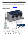
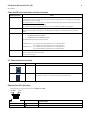
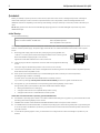
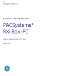
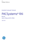
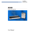
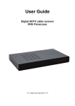
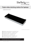
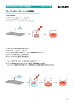
PACSystems* RXi Industrial PCs May 2014 Quick Start Guide GFK-2784E The PACSystems RXi family of industrial computers provides an advanced, high-performance computing platform. The PACSystems Box IPC delivers the flexibility of a PC with the industrial ruggedness of traditional automation controllers. Built with an open and scalable architecture, the RXi platform enables easy connectivity and allows you to maximize application reusability—supporting your current and future needs for business growth. These small form factor industrial PCs provide a number of features to support computing applications in demanding environments. ■ Dual core 1.0 GHz VIA processor ■ Multiple Gigabit Ethernet interfaces provide network implementation flexibility. ■ Built-in Data Storage – Internal disks provide highly reliable local long-term data retention. ■ USB and SD Card interfaces enable program loading, serial communications and removable data storage via standard devices. Ordering Information Catalog Number Description ICRXIBN7E000A RXi Box IPC with Embedded 32GB mSATA SSD and Windows 7 Professional, SP1 or later operating system ICRXIBN7E001A RXi Box IPC with Embedded 32GB mSATA SSD and Windows Embedded Standard 7 ICRXIBN7M000A RXi Box IPC with 250GB Magnetic SATA Hard Drive and Windows 7 Professional, SP1 or later OS ICRXIBN7M001A RXi Box IPC with 250GB Magnetic SATA Hard Drive and Windows Embedded Standard 7 ICRXIBN0E000A RXi Box IPC with Embedded 32GB mSATA SSD ICRXIBN0M000A RXi Box IPC with 250GB Magnetic SATA Hard Drive ICRXIACCBPL Optional Backplate for DIN rail mounting IC690ACC001 Real Time Clock (RTC) battery, included with IPC PACSystems RXi Industrial PCs QSG 2 GFK-2784E Specifications Dimensions: IPC Backplate 191.8mm x 115.6mm x 81.3mm (7.55 in x 4.55 in. x 3.2 in) 226 mm x 137 mm x 12 mm (8.90 in. x 5.39 in. x 0.47 in.) Weight: IPC Backplate 1.814 Kg (4 lbs) 0.454 Kg (1 lb) Processor 1.0 GHz VIA Eden dual core processor RAM 4GB DDR3 Floating point 64 bit Non-volatile storage 32GB mSATA SSD or 250GB SATA drive Non-volatile storage (NVS) can retain data indefinitely without loss of data integrity. Time of day clock (RTC) accuracy Maximum drift of ±2 seconds/day at 25°C Elapsed time clock (internal timing) accuracy ± 0.01% maximum Video Standard 15-pin VGA connector Maintenance ports (Intended only for temporary connection.) Two Type A USB 2.0 SD standard card slot Dual function Audio out/Microphone in jack (3.5mm four-pin TRRS) Power requirements 1.8 A at 24 VDC (18–32 VDC) LPS or Class 2 power supply required. Serial Communications One RS-232 RJ-45 port Ethernet Communications ICRXIBN7x000A-CA versions and earlier COM2 ICRXIBN7x001A COM1 Two Ethernet (10, 100, 1000 Mbit/s) RJ-45 ports Environmental Specifications Note: The Box IPC shall be installed in a location that is not exposed to corrosive gases or liquids, rain, or direct sunlight, and that meets the environmental specifications listed below. Vibration1 IEC60068-2-6 10 - 57 Hz, 0.006 in. displacement peak-peak 57 - 500 Hz, 1.0 g acceleration Shock IEC60068-2-27 15 g, 11ms Ambient Operating Temperature2 ICRXIBN7E000A, ICRXIBN7E001A3 ICRXIBN7M000A, ICRXIBN7M001A -25 to +65 C: [inlet] (-13° F to 149°F) 0 to +40 C: [inlet] (32° F to 104°F) Storage Temperature -40 to +85 C (-40°F to 185°F) Humidity 5% to 95%, non-condensing Environment UL60950-1 Altitude UL60950-1 Pollution Degree 2 as defined on page 3 0–2000 m 1 Applies only to Box IPCs with solid state hard drive (ICRXIBNxE00xA) 2 For ambient temperatures greater than 50°C (122°F), the unit must be installed in a restricted access area as defined below. 3 The ICRXIBN7E00xA may reduce its operating CPU frequency from 1.0 GHz to 800 MHz when operating at temperatures greater than 60C ambient. It will operate up to 65C ambient as specified, but its performance will degrade based on the lower CPU clock frequency. Warning If the Box IPC is operating in ambient temperatures greater than 50°C (122°F), its exterior temperatures may be too hot to touch safely. To avoid burn hazards, the unit must be installed in a restricted access area, as defined by: Access can only be gained by service persons or by users who have been instructed about the reasons for the restrictions applied to the location and about any precautions that shall be taken; and Access is through the use of a tool or lock and key, or other means of security, and is controlled by the authority responsible for the location. 3 PACSystems RXi Industrial PCs QSG GFK-2784E A Pollution Degree 2 environment as defined by UL60950-1: Pollution Degree 2 applies where there is only non-conductive pollution that might temporarily become conductive due to occasional condensation. For additional product standards, installation requirements and agency approvals, refer to the PACSystems RXi Box IPC User's Manual, GFK-2785. Manuals can be downloaded from the Support website, http://support.ge-ip.com. Indicators and Connectors Power On/Off Switch and Status Indicator Audio Connector SD Card Slot Blue, blinking – Booting Blue, slow fade – S3 Sleep Green, solid – Running Red, solid – Fault Connectors Indicators PACSystems RXi Industrial PCs QSG 4 GFK-2784E Power On/Off Switch and Status Indicator Operation Normal Operation† Action Power up the IPC Press and hold the button for at least ½ second. If powering up from a no-power state, the ring LED blinks blue while the IPC is booting and is solid green when the IPC is up and running. For ICRXIBN7x000A-CA or earlier only: If the system has been shut down, but power has not been cycled, the ring LED immediately turns solid green. For all other versions the ring LED blinks blue for 40 seconds before changing to solid green. Shut down the IPC Press and hold the button briefly (between 100ms and 4 seconds). The ring LED stays green while the IPC is shutting down and then turns off when the IPC is powered down. Sleep Mode The default BIOS settings when shipped from the factory are: “Enable Hibernation” is disabled ACPI Sleep State is “S1 (CPU Stop Clock)” The default settings send IPC to sleep state S1. ICRXIBN7x000A: ICRXIBN7x001A: Forced Shut down †The The ring LED stays green while the IPC is in Sleep State S1. The ring LED turns off while the IPC is in Sleep State S3 The ring LED stays green while the IPC is in Sleep State S1. The ring LED fades blue while the IPC is in Sleep State S3. Caution: Use this option only if the operating system is non-responsive: Press the button for at least 4 seconds. The ring LED turns off. ring LED displays solid red to indicate a fault, including Overtemp condition. IPC Status Indicators Operation Indicator SATA Drive Status Overtemp State Description White, blinking Read/write access on SATA drive. Red, solid The IPC’s internal temperature has exceeded the maximum allowable value. To recover, let the IPC cool, then press the Power On/Off switch. Ethernet Port LEDs Operation Each Ethernet port has two LED indicators, ACTIVITY and LINK. ACTIVITY LED LINK LED LED LED State Operating State ACTIVITY Blinking, Green Traffic is detected at the port. LINK On, Green The link is operational. 5 PACSystems RXi Industrial PCs QSG GFK-2784E Quickstart Before you attempt to power up the IPC for the first time, inspect the unit for loose or damaged components. If damage is observed (for example, in the form of bent component leads or loose components), contact GE Intelligent Platforms for additional instructions. Depending on the severity of the damage, it may be necessary to return the product to the factory for repair. Do not apply power to the unit if it has visible damage. Applying power to a unit with damaged components may cause additional damage. Initial Startup You will need the following: 24VDC, 48W power supply, Class 2 or LPS Power cord with 28 AWG –16 AWG wires VGA-compatible video monitor USB-compatible keyboard USB-compatible mouse (optional) The product is supplied with a Phoenix Contact part number 1827716 or 1851245 (spring loaded/quick release) power terminal block for use with a power supply. The power supply used must be a UL Listed Limited Power Source (LPS) or Class 2 power source. 1. Attach the power supply output to the IPC’s power plug using 16 to 28 AWG (1.31 – 0.08mm2). For frame ground, use shortest length 16 AWG (1.31mm2) wire to ground. Recommended wire stripping length is 7mm (0.28 in). Tighten the screws that hold the wires to 4 lb-in (0.452 Nm). 2. Insert the plug into the IPC’s Input Power connector and securely tighten the attaching screws. FGND 0V +24V The torque range for the attaching screws is 1.95–2.21 lb-in (0.22–0.25 Nm). 3. Connect a VGA-compatible video monitor and tighten down its attaching screws. Also attach a USB-compatible keyboard, and if desired, a USB-compatible mouse. 4. Power up the unit and check whether any concealed damage has been caused by incorrect transportation, operating/storage conditions or handling. To power up the unit, press the Power On/Off switch for at least ½ second. If you notice any damage, remove power from the unit immediately and secure it against unintentional use. 5. During power up, you should see the normal operating system starting displays on the monitor. During normal power up and operation, the Power On/Off status indicator displays: Blinking blue while the IPC is starting up Solid green when the IPC has completed startup and is running Solid green when the IPC is restarted without a loss of power Models that include the Windows 7 operating system (ICRXIBN7xxxxx): 6. The Windows 7 operating system starts in accordance with the BIOS settings. During power up, you should see the normal operating system starting displays on the monitor. 7. ICRXIBN7x001x models contain Windows Embedded Standard 7and do not require license activation. 8. For ICRXIBN7x000x, activate the Windows 7 Professional operating system license during initial power-up by following the on-screen prompts. The Windows 7 product key is printed on the Microsoft Certificate of Authenticity label, located on the right side of the IPC. 9. To activate the operating system online, you will need to first configure the IPC’s Ethernet settings for operation on your network. PACSystems RXi Industrial PCs QSG 6 GFK-2784E Shutting Down the Computer Caution For ICRXIBN7xxxxx Models, to avoid damaging files, always shut down Windows software before removing power from the IPC. Caution For ICRXIBN7xxxxx Models, do not disconnect external devices, such as a flash drive or external DVD drive without first using the Windows Safely Remove Hardware feature to eject the device. Failure to observe this precaution could result in damage to data. 1. To shut down the IPC, press the Power On/Off switch briefly (between 100ms and 4 seconds), or select Shut Down from the Windows Start menu. This provides a controlled shutdown of the operating system before removing power from the system. The status indicator stays solid green while the IPC is shutting down and then turns off when the IPC has finished powering down. 2. To completely shut down the IPC, turn off or remove the power supplying the IPC. Note: The power-off function of the On/Off switch can be disabled to avoid unplanned shutdown caused by accidentally pressing the On/Off switch. For details see GFK-2785C. Installation The IPC can be mounted on a DIN rail or panel-mounted using the ICRXIACCBPL Backplate (ordered separately). You can also mount the IPC directly onto a panel (without a Backplate). The IPC has four captive machine screws in its base for attaching the unit to the Backplate or panel. For installation guidelines and procedures, including required clearances for heat dissipation, refer to the PACSystems RXi Box IPC User's Manual, GFK-2785. RS-232 Serial Port Pin Assignments RJ-45 Pin Notes: Signal Description 8 0V 7 NC No connection 6 NC No connection 5 0V 4 NC No connection 3 Rx Receive 2 NC No connection 1 Tx Transmit The RJ-45 connector shell provides frame ground. The Serial Communication Port connector is mapped as follows: ICRXIBN7x000A-CA versions and earlier COM2 ICRXIBN7x001A COM1 For connection details for other ports, refer to GFK-2785. 7 PACSystems RXi Industrial PCs QSG GFK-2784E GE Intelligent Platforms Contact Information Americas: 1-800-433-2682 or 1-434-978-5100 Global regional phone numbers are available on our web site www.ge-ip.com www.ge-ip.com ©2014 GE Intelligent Platforms, Inc. All Rights Reserved *Trademark of GE Intelligent Platforms, Inc. All other brands or names are property of their respective holders. GFK-2784E