1
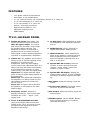
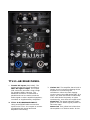
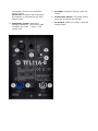
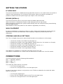
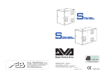
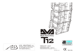
TTL11-A
ACTIVE DIGITALLY STEERABLE ARRAY
“HIGH OUTPUT AT PREMIUM SOUND QUALITY”
SAFETY PRECAUTIONS
1. All the precautions, in particular the safety ones, must be read with special attention, as
they provide important information.
2. POWER SUPPLY FROM MAINS
The mains voltage is sufficiently high to involve a risk of electrocution; install and a. connect
this product before plugging it in.
Before powering up, make sure that all the connections have been made correctly and b. the
voltage of your mains corresponds to the voltage shown on the rating plate on the unit, if not,
please contact your RCF dealer.
The metallic parts of the unit are earthed through the power cable. An apparatus with c.
CLASS I construction shall be connected to a mains socket outlet with a protective earthing
connection.
Protect the power cable from damage; make sure it is positioned in a way that it d. cannot be
stepped on or crushed by objects.
To prevent the risk of electric shock, never open this product: there are no parts inside e. that
the user needs to access.
3. Make sure that no objects or liquids can get into this product, as this may cause a short
circuit.
This apparatus shall not be exposed to dripping or splashing. No objects filled with liquid, such
as vases, shall be placed on this apparatus. No naked sources (such as lighted candles) should
be placed on this apparatus.
4. Never attempt to carry out any operations, modifications or repairs that are not expressly
described in this manual.
Contact your authorized service centre or qualified personnel should any of the following
occur:
- The product does not function (or functions in an anomalous way).
- The power cable has been damaged.
- Objects or liquids have got in the unit.
- The product has been subject to a heavy impact.
5. If this product is not used for a long period, disconnect the power cable.
6. If this product begins emitting any strange odours or smoke, switch it off immediately and
disconnect the power cable.
7. Do not connect this product to any equipment or accessories not foreseen.
For suspended installation, only use the dedicated anchoring points and do not try to hang this
product by using elements that are unsuitable or not specific for this purpose. Also check the
suitability of the support surface to which the product is anchored (wall, ceiling, structure,
etc.), and the components used for attachment (screw anchors, screws, brackets not supplied
by RCF etc.), which must guarantee the security of the system / installation over time, also
considering, for example, the mechanical vibrations normally generated by transducers.
To prevent the risk of falling equipment, do not stack multiple units of this product unless this
possibility is specified in the user manual.
8. RCF S.p.A. strongly recommends this product is only installed by professional
qualified installers (or specialised firms) who can ensure correct installation and
certify it according to the regulations in force.
The entire audio system must comply with the current standards and regulations
regarding electrical systems.
9. Supports and trolleys The equipment should be only used on trolleys or supports, where
necessary, that are recommended by the manufacturer. The equipment / support / trolley
assembly must be moved with extreme caution. Sudden stops, excessive pushing force and
uneven floors may cause the assembly to overturn.
10. There are numerous mechanical and electrical factors to be considered when installing a
professional audio system (in addition to those which are strictly acoustic, such as sound
pressure, angles of coverage, frequency response, etc.).
11. Hearing loss.
Exposure to high sound levels can cause permanent hearing loss. The acoustic pressure level
that leads to hearing loss is different from person to person and depends on the duration of
exposure. To prevent potentially dangerous exposure to high levels of acoustic pressure,
anyone who is exposed to these levels should use adequate protection devices. When a
transducer capable of producing high sound levels is being used, it is therefore necessary to
wear ear plugs or protective earphones. See the manual technical specifications to know the
maximum sound pressure level.
IMPORTANT NOTES
To prevent the occurrence of noise on line signal cables, use screened cables only and avoid
putting them close to:
- Equipment that produces high-intensity electromagnetic fields
- Power cables
- Loudspeaker lines.
OPERATING PRECAUTIONS
Place this product far from any heat sources and always ensure an adequate air circulation
around it.
Do not overload this product for a long time.
Never force the control elements (keys, knobs, etc. ).
Do not use solvents, alcohol, benzene or other volatile substances for cleaning the external
parts of this product.
IMPORTANT NOTES
Before connecting and using this product, please read this instruction manual carefully and
keep it on hand for future reference. The manual is to be considered an integral part of this
product and must accompany it when it changes ownership as a reference for correct
installation and use as well as for the safety precautions. RCF S.p.A. will not assume any
responsibility for the incorrect installation and / or use of this product.
WARNING: To prevent the risk of fire or electric shock, never expose this product to rain or
humidity.
TT+ HIGH DEFINITION TOURING AND THEATRE
RCF TT+ represents another prominent chapter in the long history of RCF Sound Systems.
Whether a speaker system is designed for live sound or large concert situations as well as
permanent installed theatre sound applications, the paying customer now expects a level of
audio fidelity and intelligibility of such a standard unsurpassed by previous generations.
This requirement has fostered the need for Audio Professionals to be able to offer a range of
speaker systems combined with dedicated transducer and crossover technologies that are
superior in acoustic performance and control.
RCF TT+ offers ready to use solutions and tools in true high definition speaker systems.
INNOVATION INTEGRATION INTENSITY
INNOVATION. Our research and engineering faculty can today offer innovative projects with
finite control of each detail, from the loudspeaker voice coil wire to the highly efficient
extended dynamic amplifier topology.
There are many different ingredients that go into creating quality products and systems. These
include computer aided simulation software to assist the understanding of transducer
behaviour and amplifier operation and the relationship of dynamics and transient response.
RCF utilise over thirty state of the art software packages to identify magnetic circuits, voice
coil dynamics, suspension linearity, horn dispersion simulation, crossover filters, amplifier
thermal behaviour etc.
INTEGRATION. RCF is one of only a few loudspeaker manufacturers worldwide who have the
ability to completely design and manufactures transducers, speaker systems and amplification
and control electronics. Our 50 plus years heritage in Audio combined with our state of the art
research and development and manufacturing processes allows us to seamlessly integrate all
the ingredients to design and build TT+
INTENSITY. The design philosophy for the new TT+ series is based upon offering the sound
engineer solutions and tools that are ready to use. Key factors are the ability to sustain very
high power with highly efficient sound pressure levels. Intense sound levels are created with
extremely high definition and extended dynamic range. Modern construction materials result in
mechanical weight ratios that are light for practical flying and portability.
TT011-A, ACTIVE, DIGITALLY STEERABLE , ARRAY
The TTL11A is an active column speaker array system composed by two modules,
one for the mid-high and one for the bass frequencies.
The TTL11A-H is the HF module and is equipped with four 2.5” neodymium compression
drivers with 1.5” exit throat.
The TTL11A-B is the bass frequency section of the system and features four 8” neodymium
woofers with 2.5” voice coil for a perfect and powerful mid-bass response.
With the addition of the new TTS26-A subwoofer, the TTL11A system becomes a powerful,
compact and high definition live sound system.
FEATURES
-
Tour grade cabinet and mechanics
4000 Watt, 9 way amplification
4 x 1.4” titanium dome, neo compression drivers, 2.5” voice coil
3 x 8” neo midranges, 2.5” voice coil
4 x 8” neo woofers, 2.5” voice coil
96 KHz, 32 bit dsp processing
Digital steering down to -10°
Maximum output per size
RDNet Ready
TTL11-AH REAR PANEL
1. Female Xlr inputs (bal/unbal). The
system accept XLR input connectors.
Male Xlr signal output. The output
XLR connector provides a loop trough
for speakers daisy chaining. The
balanced connector is connected in
parallel and can be used to send the
audio signal to other amplified speakers,
recorders or supplementary amplifiers.
2. Limiter led. The amplifier has a built in
limiter circuit to prevent clipping of the
amplifiers or overdriving the
transducers. When the soft clipping
circuit is active the LED blinks RED. It is
okay if the limit LED blinks occasionally.
If the LED blinks frequently or lights
continuously, turn down the signal level.
Signal led. The signal indicator lights
green if there is audio signal present on
the main input.
Status led. This yellow led is ON when
the amplifier is in failure mode. In this
case please contact the closest RCF
service centre.
Power led. this green led is ON when
the speaker is connected to the main
power supply
3. Sensitivity control. Adjust the
amplifier sensitivity. This control does
not affect the “Link” - “Input - Link”
output level.
4. TTL11 A-B PROCESSED OUTPUT.
Using a cat5 RJ45 cable connect this
output to the TTL11 A-B input to send
processed audio signal and receive
amplifiers monitoring.
5. LF High-Pass. When switched on apply
to the speaker a 24 dB/Octave filter at
100 Hz
6. RDNet Bypass. When switched on
bypass any speaker RDNet preset.
7. Wall Placement. When switched on
apply to the speaker a special shelving
filter to optimise the curve response
when the speaker is placed close to a
wall or to the floor.
8. System SET UP encoder. Push the
encoder to move through functions
(height – throw, delay), rotate the
encoder to select a value.
9. System SET UP display. Display the
system setting values. In case of RDNet
connection a rotating segment will light
up.
10.AC Input. Powercon locking 3-pole AC
mains
11.Power main switch. The power switch
turns the AC power ON and OFF.
12.AC Output. Powercon locking 3-pole AC
mains output.
13.RDNet Option. The AC RDNET IN/OUT
PLUG optional accessory is installed
removing this panel.
TTL11-AB REAR PANEL
1. Female Xlr inputs (bal/unbal). The
system accept XLR input connectors.
Male Xlr signal output. The output
XLR connector provides a loop trough
for speakers daisy chaining. The
balanced connector is connected in
parallel and can be used to send the
audio signal to other amplified speakers,
recorders or supplementary amplifiers.
2. TTL11 A-H PROCESSED INPUT.
Using a cat5 RJ45 cable connect this
input to the TTL11 A-H output to receive
processed audio signal and send
amplifiers monitoring.
3. Limiter led. The amplifier has a built in
limiter circuit to prevent clipping of the
amplifiers or overdriving the
transducers. When the soft clipping
circuit is active the LED blinks RED. It is
okay if the limit LED blinks occasionally.
If the LED blinks frequently or lights
continuously, turn down the signal level.
Signal led. The signal indicator lights
green if there is audio signal present on
the main input.
Status led. This yellow led is ON when
the amplifier is in failure mode. In this
case please contact the closest RCF
service centre.
Power led. this green led is ON when
the speaker is connected to the main
power supply
4. Sensitivity control. Adjust the
amplifier sensitivity. This control does
not affect the “Link” - “Input - Link”
output level.
5. AC Input. Powercon locking 3-pole AC
mains
6. Power main switch. The power switch
turns the AC power ON and OFF.
7. AC Output. Powercon locking 3-pole AC
mains output.
SETTING THE SYSTEM
LF HIGH PASS.
This control introduces a 24 dB/octave high pass filter at 90 Hz. It is useful when the system is
used for vocal reproduction, for a cleaner vocal output. When this switch is pressed it is
possible to obtain from the system higher spl output in the vocal range.
BYPASS (RECALL).
This control must be used in conjunction with the RDNet optional board.
When the switch is released the system reads settings from the input board.
When the switch is pressed the system reads settings from the internal memory saved during
the last RDNet session.
When RDNet is active the position of the switch is bypassed (not influent).
WALL PLACEMENT
In case of installation or positioning close to a wall, pressing this switch the system apply an
equalisation to correct the behaviour of the frequency response (modified by the wall
reflections).
STEERING AND DELAY SETTINGS
The TTL11-A digital array can be steered and focused to the audience in a few steps:
-
1.
2.
3.
4.
5.
6.
Press the encoder, the HEIGHT led will light up.
Rotate the encoder to the right HEIGHT setting (from 0 to 2.0 meters in 0.5 steps)
Press the encoder, the THROW led will light up.
Rotate the encoder to the right THROW (near, mid, far, ∞ ).
Press the encoder, the DELAY led will light up.
Rotate the encoder to the right DELAY setting.
The HEIGHT of installation is referred to the base of the TTL11 BA.
The DELAY is expressed in 0.1 meter until 10 meters and in meter from 10 to 20 meters.
CONNECTIONS
The XLR connectors use the following AES standard:
PIN 1 = GROUND (SHIELD)
PIN 2 = HOT (+)
PIN 3 = COLD (-)
The audio XLR cable shall be connected:
- 1. To TTL11 AH signal input
- 2. From TT11 AH signal link to TL11 BA signal input
In case of use of the system in conjunction to the TTS 26-A subwoofer the audio XLR cable
shall be connected:
-
1. To TTS 26-A signal input
2. From TTS 26-A XOVER output to the TTL11 AH signal input
3. From TT11 AH signal link to TL11 BA signal input
BEFORE TURNING ON THE SPEAKER
At this point you can connect the power supply cable and the signal cable, but before turning
on the speaker make sure that the volume control is at the minimum level (even on the mixer
output). It is important that the mixer is already ON before turning on the speaker. This will
avoid damage to the speakers and noisy “bumps” due to turning on parts on the audio chain.
It is a good practice to always turn on speakers at last and turn them off immediately after the
show.
Now you can turn ON the speaker and adjust the volume control to a proper level.
INSTALLATION
The top and bottom of the speaker is provided with a special mounting plate. To the mounting
plate accessories for pole mounting or truss clamping can be assembled.
TT+ speakers MUST be suspended only with RCF approved rigging hardware.
WARNING: Daisy chaining speakers always make sure that the maximum current
requirement does not exceed the maximum admitted POWERCON current. In case of doubt call
the closest RCF SERVICE CENTRE.
VOLTAGE SETUP (RESERVED TO THE RCF SERVICE CENTRE)
TTL11-AH
230 Volt, 50 Hz SETUP : FUSE VALUE T 1.25 A L 250 V
115 Volt, 60 Hz SETUP : FUSE VALUE T 3.15 A H 250 V
TTL11-BA
230 Volt, 50 Hz SETUP : FUSE VALUE T 1.25 A L 250 V
115 Volt, 60 Hz SETUP : FUSE VALUE T 3.15 A H 250 V
TECHNICAL SPECIFICATIONS
ACOUSTICAL
Operating frequency range
Max SPL
Coverage
Crossover point
TTL11-AH
TTL11-AB
150 – 20.000 Hz
136 dB
10° to 40°
350 -1.300 Hz
60 – 300 Hz
133 dB
90° x 40°
350 Hz
TRANSDUCERS
Low frequency
Mid frequency
High frequency
4 x 8” mid-bass
3 x 8” midranges
4 x 2.5” v.c. titanium drivers
AMPLIFIER
Total power
Low section
Mid Section
High section
2000 Watt
2000 Watt
2 x 1000 Watt
3 x 350 Watt
4 x 250 Watt
CONNECTIONS
Signal Input/Output XLR male/female
Power Input/Output Powercon male/female
CONTROLS
High pass, wall mounting, RDNet bypass,
Sensitivity Control
SYSTEM SETTINGS
Height, Throw, Delay
ANALOG INPUT
2 way equalisation, crossover filtering
fast limiter, RMS limiter
MECHANICAL
Size
Weight
1198 x 261 x 242
39 Kg
1198 x 261 x 242
37 Kg