1
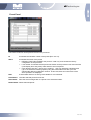
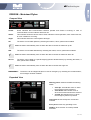
dBTechnologies DEVICE PLUGINS Software version 2.0 Document version 2.0 dBTechnologies DVA T8 and DVA T12 – Line Array Module ................................................................................................... 3 Compact View ................................................................................................................................................ 3 Expanded View .............................................................................................................................................. 3 DVA S1518N (Sub 18” Bandpass) and DVA S1521N (Sub 21” Bassreflex) ............................................... 5 Compact View ................................................................................................................................................ 5 Expanded View .............................................................................................................................................. 5 DVA S2585N (Sub, 18” + 15” Cardioid) ......................................................................................................... 7 Compact View ................................................................................................................................................ 7 Expanded View .............................................................................................................................................. 7 DVA S30N (Sub, 2x18” Bassreflex Horn Loaded) ........................................................................................ 9 Compact View ................................................................................................................................................ 9 Expanded View .............................................................................................................................................. 9 AC26N – Digital Audio Processor ................................................................................................................ 11 Compact View .............................................................................................................................................. 11 Expanded View ............................................................................................................................................ 11 X-Over Panel ................................................................................................................................................ 12 PEQ Panel ................................................................................................................................................... 13 Compressor Panel ....................................................................................................................................... 14 Preset Panel ................................................................................................................................................. 15 DRK20M – Motorized Flybar ......................................................................................................................... 16 Compact View .............................................................................................................................................. 16 Expanded View ............................................................................................................................................ 16 2/17 Rev . dBTechnologies DVA T8 and DVA T12 – Line Array Module Compact View Comm: Green indicates that communication between speaker and Control is working. In case of communication error the indicator becomes red. Eq. Sync: Green indicates that actual device Eq. is synchronized with either the Group. Eq and 2 showed in the DVA Network software. Status: This indicator shows the device status. Green indicates normal operation; when it becomes red, an error condition is occurring. MUTE: The device can be muted by selecting the button; it turns red when enabled. SOLO: Allows to listen to only to the selected device. Other devices will be automatically muted. nd Eq Light indicators under Speaker Image: shows status of each audio way (Midrange, tweeter and woofer): 1. Green: audio level of the relevant channel exceeds -40dBfs (decibel full. scale, 0dBfs = maximum power delivered by channel amplifier) 2. Red: amplifier delivers maximum power and limiter is active. Vu-meter bars: 1. left bar (green) indicates the input signal level (in dBu) 2. right bar (red) indicates the limiter compression level (in dB) (average of the 3 audio ways) An indicator located above signal level becomes red when maximum signal level allowed on preamplifier input is reached. Expanded View MF-HF-LF Panels: show advanced parameters for each audio way (Midrange, Tweeter and Woofer). 3/17 Rev . dBTechnologies Each panel contains: Vu-meter bar on the left (green): channel amplifier output level in dBfs (decibel full. scale, 0dBfs = maximum power delivered) ; Vu-meter bar on the right (red): channel limiter compression level in dB; amplifier temperature: indicated in °C Status indicator: green = channel is ok; Red = malfunction is detected; MUTE: single audio way mute Preset panel: Select a different audio preset Hpf preset panel: Select a different HPF audio preset Note: HPF filter is a Linkwitz–Riley high pass filter with a slope of 24dB/oct that is cascaded in the input of the audio path of the device. User can change the Crossover frequency. Filters are tuned to perfectly match the Low pass filters present in DVA Rdnet equipped subwoofer To obtain best performances is best to select the same xover frequency for both Speakers and Subwoofer If Digital HPF filter is used in the top speakers it's important to connect the same audio source to sub and tops and avoid to use Xover Out source present in the DVA subwoofers Thermal Limiter: becomes yellow when amplifier module starts reducing Audio volume to prevent overheating. FW Rev: Show revision of currently loaded Firmware. Temp: Indicates PSU temperature in °C. Standby: enter in standby mode to reduce internal temperature and energy consumption in long inactivity conditions. Button is usually green and becomes red in "stand-by" condition. Anyway, DVA Network communication remains active and speaker can be reactivated at any time by pressing the key again. ATTENTION!! If activated, standby button will switch PSU module off and will deactivat audio on all 3 output channels. Factory Default: Allows to reset all settings made via DVA Network software and to restore factory configuration settings. ATTENTION Speaker must be assigned to a group in order to modify the audio equalization. 4/17 Rev . dBTechnologies DVA S1518N (Sub 18” Bandpass) and DVA S1521N (Sub 21” Bassreflex) Compact View Comm: Green indicates that communication between speaker and Control is working. In case of communication error the indicator becomes red. Eq. Sync: Green indicates that actual device Eq. is synchronized with the Group. Eq showed in the DVA Network software. Status: This indicator shows the device status. Green indicates normal operation; when it becomes red, an error condition is occurring. MUTE: The device can be muted by selecting the button; it turns red when enabled. SOLO: Allows to listen to only to the selected device. Other devices will be automatically muted. Light indicators under Speaker Image: shows the audio status: 1. Green: audio level of the relevant channel exceeds -40dBfs (decibel full. scale, 0dBfs = maximum power delivered by channel amplifier) 2. Red: amplifier delivers maximum power and limiter is active. Vu-meter bars: 1. left bar (green) indicates the input signal level (in dBu) 2. right bar (red) indicates the limiter compression level (in dB) An indicator located above signal level becomes red when maximum signal level allowed on preamplifier input is reached. Expanded View Woofer-Xover Out Panels: show advanced parameters for each audio way (Woofer Out and Xover Out). 5/17 Rev . dBTechnologies Each panel contains: Vu-meter bar on the left (green): channel amplifier output level in dBfs (decibel full. scale, 0dBfs = maximum power delivered) ; Vu-meter bar on the right (red): channel limiter compression level in dB; Status (or active) indicator: green = channel is ok; Red = malfunction is detected; MUTE: single audio way mute Delay Preset panel: Select a different audio Delay preset (see Speaker User manual). Delay is indicated in mS and ranges from 0 to 4.5mS in step of 0.5mS. The following formula can be used to align an audio signal: Delay = (GAPx1000)/344 Delay = ms (in milliseconds) GAP = distance between speaker and reference point (in meters) Speed of sound = 344 m/s Inv. Phase performs a phase rotation of 180° respect to the input signal. It turns red when phase rotation is active. Xover Preset panel: Select a different audio preset for Xover (see Speaker User manual). Woofer Low Pass Cut-off Frequency can be selected in step of 5Hz with a slope of 24dB/oct. An HighPass filter with the same cut-of frequency will be automatically applied to Xover Out. FW Rev: Show revision of currently loaded Firmware. Temp: Indicates PSU temperature in °C. Standby: enter in standby mode to reduce internal temperature and energy consumption in long inactivity conditions. Button is usually green and becomes red in "stand-by" condition. Anyway, DVA Network communication remains active and speaker can be reactivated at any time by pressing the key again. ATTENTION!! If activated, standby button will switch PSU module off and will deactivat audio on all 3 output channels. Factory Default: Allows to reset all settings made via DVA Network software and to restore factory configuration settings. ATTENTION Speaker must be assigned to a group in order to modify the audio equalization. 6/17 Rev . dBTechnologies DVA S2585N (Sub, 18” + 15” Cardioid) Compact View Comm: Green indicates that communication between speaker and Control is working. In case of communication error the indicator becomes red. Eq. Sync: Green indicates that actual device Eq. is synchronized with the Group. Eq showed in the DVA Network software. Status: This indicator shows the device status. Green indicates normal operation; when it becomes red, an error condition is occurring. MUTE: The device can be muted by selecting the button; it turns red when enabled. SOLO: Allows to listen to only to the selected device. Other devices will be automatically muted. Light indicators under Speaker Image: shows the audio status: 1. Green: audio level of the relevant channel exceeds -40dBfs (decibel full. scale, 0dBfs = maximum power delivered by channel amplifier) 2. Red: amplifier delivers maximum power and limiter is active. Vu-meter bars: 1. left bar (green) indicates the input signal level (in dBu) 2. right bar (red) indicates the limiter compression level (in dB) An indicator located above signal level becomes red when maximum signal level allowed on preamplifier input is reached. Expanded View Woofer Front - Xover Out Panels: show advanced parameters for each audio way (Main Woofer and Xover Out). Each panel contains: Vu-meter bar on the left (green): channel amplifier output level in dBfs (decibel full. scale, 0dBfs = maximum power delivered) ; Vu-meter bar on the right (red): channel limiter compression level in dB; Status Amp Front indicator: status of the front woofer audio channel; green = channel is ok; Red = malfunction is detected; Status Amp Rear indicator: status of the Rear woofer audio channel; green = channel is ok; Red = malfunction is detected; MUTE: single audio way mute 7/17 Rev . dBTechnologies Delay Preset panel: Select a different audio Delay preset (see Speaker User manual). Delay is indicated in mS and ranges from 0 to 4.5mS in step of 0.5mS. The following formula can be used to align an audio signal: Delay = (GAPx1000)/344 Delay = ms (in milliseconds) GAP = distance between speaker and reference point (in meters) Speed of sound = 344 m/s Inv. Phase performs a phase rotation of 180° respect to the input signal. It turns red when phase rotation is active. Xover Preset panel: Select a different audio preset for Xover (see Speaker User manual). Woofer Low Pass Cut-off Frequency can be selected in step of 5Hz with a slope of 24dB/oct. An HighPass filter with the same cut-of frequency will be automatically applied to Xover Out. Cardioid Preset SC = Super Cardioid. Rear attenuation range is 135° with respect to the front. This configuration is used when the speakers are positioned laterally to stages whose width is between 6 and 14 metres. C = Cardioid (heart shaped diagram). Rear attenuation range is 180° (in line with the front). This configuration is to be used if the speaker is placed in front of the stage in a central position; in this case the low frequencies are practically eliminated on stage. HC = Hypercardioid. Rear attenuation range is 120° with respect to the front. This is the recommended configuration when the speakers are arranged laterally to stages whose width is over 14 meters. FW Rev: Show revision of currently loaded Firmware. Temp: indicates PSU temperature in °C. Standby: enter in standby mode to reduce internal temperature and energy consumption in long inactivity conditions. Button is usually green and becomes red in "stand-by" condition. Anyway, DVA Network communication remains active and speaker can be reactivated at any time by pressing the key again. ATTENTION!! If activated, standby button will switch PSU module off and will deactivat audio on all 3 output channels. Factory Default: Allows to reset all settings made via DVA Network software and to restore factory configuration settings. ATTENTION Speaker must be assigned to a group in order to modify the audio equalization. 8/17 Rev . dBTechnologies DVA S30N (Sub, 2x18” Bassreflex Horn Loaded) Compact View Comm: Green indicates that communication between speaker and Control is working. In case of communication error the indicator becomes red. Eq. Sync: Green indicates that actual device Eq. is synchronized with the Group. Eq showed in the DVA Network software. Status: This indicator shows the device status. Green indicates normal operation; when it becomes red, an error condition is occurring. MUTE: The device can be muted by selecting the button; it turns red when enabled. SOLO: Allows to listen to only to the selected device. Other devices will be automatically muted. Light indicators under Speaker Image: shows the audio status for each woofer: 1. Green: audio level of the relevant channel exceeds -40dBfs (decibel full. scale, 0dBfs = maximum power delivered by channel amplifier) 2. Red: amplifier delivers maximum power and limiter is active. Vu-meter bars: 3. left bar (green) indicates the input signal level (in dBu) 4. right bar (red) indicates the limiter compression level (in dB) An indicator located above signal level becomes red when maximum signal level allowed on preamplifier input is reached. Expanded View Woofer 1 – Woofer 2 -Xover Out Panels: show advanced parameters for each audio way. Each panel contains: Vu-meter bar on the left (green): channel amplifier output level in dBfs (decibel full. scale, 0dBfs = maximum power delivered) ; Vu-meter bar on the right (red): channel limiter compression level in dB; Status (or active) indicator: green = channel is ok; Red = malfunction is detected; MUTE: single audio way mute Delay Preset panel: Select a different audio Delay preset (see Speaker User manual). Delay is indicated in mS and ranges from 0 to 4.5mS in step of 0.5mS. 9/17 Rev . dBTechnologies The following formula can be used to align an audio signal: Delay = (GAPx1000)/344 Delay = ms (in milliseconds) GAP = distance between speaker and reference point (in meters) Speed of sound = 344 m/s Inv. Phase Performs a phase rotation of 180° respect to the input signal. It turns red when phase rotation is active. Xover Preset panel: Select a different audio preset for Xover (see Speaker User manual). Woofer Low Pass Cut-off Frequency can be selected in step of 5Hz with a slope of 24dB/oct. An HighPass filter with the same cut-of frequency will be automatically applied to Xover Out. FW Rev: Show revision of currently loaded Firmware. Temp: Indicates PSU temperature in °C. Standby: enter in standby mode to reduce internal temperature and energy consumption in long inactivity conditions. Button is usually green and becomes red in "stand-by" condition. Anyway, DVA Network communication remains active and speaker can be reactivated at any time by pressing the key again. ATTENTION!! If activated, standby button will switch PSU module off and will deactivat audio on all 3 output channels. Factory Default: Allows to reset all settings made via DVA Network software and to restore factory configuration settings. ATTENTION Speaker must be assigned to a group in order to modify the audio equalization. 10/17 Rev . dBTechnologies AC26N – Digital Audio Processor Compact View Comm: Green indicates that communication between speaker and Control is working. In case of communication error the indicator becomes red. Status: This indicator shows the device status. Green indicates normal operation; when it becomes red, an error condition is occurring. MUTE: The device can be muted by selecting the button; it turns red when enabled. The general mute has the highest priority with respect to the muting of individual channels. Input A-B / Output 1-6 panels: each panel indicates the audio status of the corresponding channel. Left side bar (green) shows the signal level in dBu (in dBfs for inputs if Digital Source is selected). Right side bar (red) indicates the compression level of the compressor (in dB) Expanded View Left side panel (gray): hosts the general processor configurations: Input A-B source This option allows to set the type of input audio signal: • Analog In: Analog audio signals (“A” and “B” inputs) • Digital In: Digital Audio signals (“AES/EBU” inputs) Digital in Pad This option allows to set the type of digital AES input: • No Pad: digital AES input is not attenuated • -20 dB Pad: digital AES input is attenuated of -20 dB 11/17 Rev . dBTechnologies Digital Out Source This option allows to select the audio source that will be forwarded to the connector AES/EBU OUT (digital output) • Analog In: Audio signals sourced from analog inputs • Digital In: Audio signals sourced from digital inputs • Output 1-2: Audio signals sourced from outputs 1 and 2 • Output 3-4: Audio signals sourced from outputs 3 and 4 • Output 5-6: Audio signals sourced from outputs 5 and 6 • Input A-B: Audio signals sourced from input A and B processing channel Input A-B link It allows to configure the inputs in stereo and joined modes, so that all the filters, compressors, delays, volumes, ... of the two inputs will have the same values. If active, “LINKED” button will light up red. X-Over Panel This window allows to select for each output a low pass filter and an high pass filter for each output, or to create a band-pass filter via the combination of both. Graphic filters of the individual outputs are identified using the colors shown in the configuration menu. The configuration can be performed directly on the graph, by moving the relevant square colored cursor with the mouse, or analytically by inserting the data in the option boxes. Option boxes are composed by the following fields: Enabled: Activate the filter. Type: 1. 2. HPF: High-pass filter. Set to allow only the part of audio signal above the cut-off frequency LPF: Low-pass filter. Set to allow only the part of audio signal below the cut-off frequency Slope: To select the attenuation slope of the audio signal on the basis of the desired attenuation. The higher the signal slope, at the same cut-off frequency, the greater the signal selection. Freq (Hz): To set the passing frequency for the lower frequencies only (low-pass filter) or the higher frequencies only (high-pass filter). 12/17 Rev . dBTechnologies PEQ Panel PEQ panel allows to equalize each single Input or Output channel, correcting one or more frequencies that have to be reduced or increased. The graphs shows a red line that represent the resultant of all activated filters. Each single filter Frequency response will be showed in white and will become Green when the corresponding filter is selected. Filter parameters can be edited by moving the round icon on the graph or analytically by inserting the data in the option boxes. Enabled: Type: Select the relevant dedicated box to activate the filter development To configure the kind of equalizer. • PEQ (Peaking equalizer): Correct only a defined range of frequencies. • SHF (High-shelf Equalizer): All frequencies pass, but frequencies above the selected cut-off frequency are increased or attenuated by the given gain. • SHF (Low-shelf Equalizer): All frequencies pass, but frequencies below the selected cutoff frequency are increased or attenuated by the given gain. Bw (only available with PEQ filters): It defines the range of frequencies where the filter work; the greater the value of Bw, the narrower is the frequencies range. Gain: It set the gain of the selected frequencies. If the gain exceeds 0 dB the signal is amplified, while if the gain is lower than 0 dB the signal is attenuated. Freq : To set the filter central or cut-off frequency. 13/17 Rev . dBTechnologies Compressor Panel Compressor panel shows the compression status for the corresponding audio channel. The compression diagram is in green colour. The configuration can be performed on the graph, by moving the circle with the relevant letter or analytically by inserting the data in the option boxes, or else by moving sliders. Threshold: Identifies the threshold where the compression ratio begins. Base is 1:1 Ratio: Indicates the conversion ratio between input and output signal. Post Gain: Applies output gain applied after the compressor. Attach Time: Set compressor attack time Release Time: Set compressor release time Hold time: Set compressor hold time Flatten: Reset all parameters to default values (no compression applied) By pass: It allows to bypass the compressor. Save: It allows to save the configuration of one individual channel Load: It allows to load a previously saved configuration. Send: Sends the changed data of each individual channel to the processor. This operation is normally carried out by the system in real time while the parameters are being modified 14/17 Rev . dBTechnologies Preset Panel The Preset List shows all the presets stored on the processor. Id: It indicates the Identifier number of the preset (from 0 to 31). Name: It indicates the name of the preset • DEFAULT FACTORY PRESET: this preset is “read only” and contains the factory configuration of the processor. • Local Preset: It indicates that the preset was saved via the processor local user interface (LCD display and rotary knob). Date and time are not reported. • User desired name (Eg. “Arena 12 pro system”): User can associate a desired name (up to 16 characters including spaces) using the Preset Name box after you have selected the desired configuration number. In this case, date and current time of the Save operation are displayed. It shows date and time of saving. Not available for Local Presets. Date: Load Button: Load the selected preset from the list. Save Button: Save the actual configuration to a preset in the selected location. Delete Button: Delete selected preset. 15/17 Rev . dBTechnologies DRK20M – Motorized Flybar Compact View Comm: Green indicates that communication between speaker and Control is working. In case of communication error the indicator becomes red. Status: This indicator shows the device status. Green indicates normal operation; when it becomes red, an error condition is occurring. Angle: This indicator shows the current flybar's tilt angle UP: The device can be tilted upward by selecting the button; it turns yellow when enabled. Note: the button automatically turns off when the device reaches its maximum up tilt DW: The device can be tilted downward by selecting the button; it turns yellow when enabled. Note: the button automatically turns off when the device reaches its maximum down tilt GO TO: The device can be tilted to a specific angle (typed into textbox above) by selecting the button; it turns yellow when enabled. Note: the button automatically turns off when the device reaches the angle set EMERGENCY: The device can be stopped anytime in case of emergency by selecting the rounded button; it turns bright red when enabled. Expanded View Warning panel: shows three different warning states: Limit Up: this indicator turns on when the maximum up tilt is reached Limit Down: this indicator turns on when the maximum down tilt is reached Locked: this indicator turns on when the emergency button is pressed View panel: shows the flybar's current tilt in real time Error panel: shows any operating errors FW Rev: Show revision of currently loaded Firmware. 16/17 Rev . dBTechnologies October 2014 R&D Dept. dB Technologies a brand of A.E.B. Industriale Srl [email protected] www.dbtechnologies.com 17/17 Rev .