1
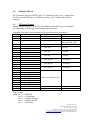
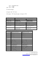
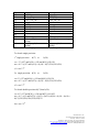
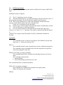
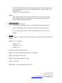
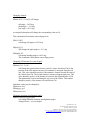
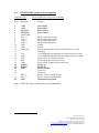
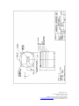
DMARS/GARS User’s Manual
1.0
GENERAL INFORMATION
1.1
Unpacking/Handling:
DMARS/GARS is a very delicate instrument. It contains gyroscopes and
accelerometers which are mechanically and electrically sensitive. Please exercise extreme
caution when handling the system.
Electrostatic:
DMARS/GARS is an electrostatic sensitive device. A standard anti-static procedure
has to be exercised. Please do not remove the anti-static cap from the connector whenever
DMARS/GARS is not in use.
Mechanical Shock:
DMARS/GARS is sensitive to mechanical shock and vibration. It's calibration
constants may be changed as a result of any possible damage. The Crash Safety shock
is 15g 11ms one time per direction.
1.2
Mounting:
Fastener:
DMARS/GARS is provided with four (4) 0.200 inch mounting holes on a 4.800 inch
diameter. These holes are for UNC 10-24 hexnut screws with washers. The recommended
screw mounting torque is 30 ounce-inch.
Orientation:
DMARS/GARS is an omni-directional system which compensates its mounting matrix
to orient its desired direction, however, its default orientation is labeled on the
DMARS/GARS. The roll axis should be parallel to that of the vehicle, meanwhile, the
yaw axis should be facing down. Since the DMARS/GARS's thermal characteristics have
been calibrated with it's yaw in the down position, a better performance is expected in
this position compared to being in the upside down position. Any mounting misalignment
angles and positions should be measured and compensated by using the IS_PC_CDU
program. Please refer to the IS_PC_CDU software. To ensure the mounting repeatability,
please use a 2 dowel pin arrangement against a reference surface indicated in the
attachment #1 drawing.
Mounting Surface:
A flat mounting surface with a flatness of 0.001/inch and a roughness better than 65rms is
preferred. Please notice that there is a 0.015 mounting clearance indentation under the
mounting surface. (Please refer to attachment #1).
Inertial Science, Inc.
3533 Old Conejo Road, Suite #104
Newbury, Park, CA 91320
Telephone: (805) 499-3191, Fax: (805) 498-4882
http://www.inertialscience.com, email: [email protected]
Copyright © 2003, Inertial Science, Inc., All Rights Reserved.
Heat Sink Consideration:
DMARS/GARS generates 17 Watts of power. A 12"x12"x1/2" aluminum mounting plate
or a larger thermal mass is sufficient to dissipate the heat.
An add-on heat sink is available as an option, upon request.
GPS Antenna mount:
A pair of magnetic fasteners and two 4-40 tap holes are also available under the antenna.
Please mount the antenna where a maximum satellite visibility, solid angle, is available.
1.3
Connector:
A 26 pin high density D-type female connector, CONEC Corp. 241A16510
or equivalent, is mating connector.
Wiring:
The following pins should be wired and connected before use.
pin 1 (awg 26 or larger) to +28v power input
pin 2 (awq 26 or larger) to +28v power input
pin 3 (awg 26 or larger) to power return
pin 4 (awg 26 or larger) to power return
(AWG 22 preferred)
(AWG 22 preferred)
(AWG 22 preferred)
(AWG 22 preferred)
note: Power in reverse polarity is protected.
pin 19 (shielded twisted pair line 1) to pin 2 of PC com connector
pin 20 (shielded twisted pair line 2) to pin 3 of PC com connector
pin 21 (shielded twisted pair shield) to pin 5 of PC com connector
pin 26 (awg 26 or larger) to chassis ground or to power return
other pins are factory use or disabled. Please leave them open.
Cable Clamping:
A cable clamp is provided for both the main connector and the antenna wires.
1.4
Power-on sequence:
The GPS antenna is not necessary for the power on sequence, but we recommend that it
be connected to the DMARS/GARS, before power-on.
Power On:
0 to 20 seconds: Performs initialization and BITE
20th second: Communication starts. IS_PC_CDU starts to show data.
Inertial Science, Inc.
3533 Old Conejo Road, Suite #104
Newbury, Park, CA 91320
Telephone: (805) 499-3191, Fax: (805) 498-4882
http://www.inertialscience.com, email: [email protected]
Copyright © 2003, Inertial Science, Inc., All Rights Reserved.
20 to 45 seconds: Gyros go into initialization. It is normal to hear a chirping noise
during the spin-up period, or during a cold start.
45th second: DMARS/GARS is in zero velocity damping mode, and is in Coarse
heading (yaw)_align mode. This coarse align function will be replaced by heading
input ($INhdgxxx.xxx), or by an available GPS heading.
100 to 400 seconds: GPS fixes its position. Position fixing time varies depending
on the conditions. The DMARS/GARS contains a back-up battery to power the
GPS’s quick acquisition function. This back-up battery should last more than 3
years.
Reacquisition should take:
Cold start <160 sec
Warm start <45 sec
Hot start <20 sec
45 sec after power on
After the GPS fix: DMARS/GARS zero velocity damping mode is terminated and
replaced by a GPS aided mode.
When the GPS OK sign is on, the DMARS/GARS is ready for navigation. As long as the
GPS signal is valid, DMARS/GARS navigates using the GPS aided mode, and a short
term interruption of the GPS signal will not effect the navigation quality.
If a GPS signal is not healthy for a longer period, the DMARS/GARS has other
navigational modes. Please refer to IS_PC_CDU section for further details.
1.5
Calibration
DMARS/GARS may not require any periodic calibration. By the read-out, some
parameters in the DMARS/GARS E2 prom may indicate the health of the system. Please
contact the factory for further details.
1.6
Warranty and Repair
ISI warrants to Buyer that at the time of shipment the products will be free from defects
of material and workmanship and will conform to the applicable ISI drawings and
specifications. Should any such defect become apparent within 12 months from delivery
thereof to Buyer, ISI’s sole obligation under this warranty will be limited to either, at
Inertial Science, Inc.
3533 Old Conejo Road, Suite #104
Newbury, Park, CA 91320
Telephone: (805) 499-3191, Fax: (805) 498-4882
http://www.inertialscience.com, email: [email protected]
Copyright © 2003, Inertial Science, Inc., All Rights Reserved.
ISI’s option and expense, repairing, replacing or extending credit for the products or parts
thereof returned to ISI by Buyer, F.O.B. ISI’s plant, and which ISI reasonably determines
do not conform to the warranty and Buyer’s exclusive remedy for breach of such
warranty will be enforcement of such obligation.
The foregoing warranty is exclusive and in lieu of all other warranties, whether express,
implied or statutory, including, but not by way of limitation, any warranty of
merchantability of fitness for any particular purpose.
Inertial Science, Inc.
3533 Old Conejo Road, Suite #104
Newbury, Park, CA 91320
Telephone: (805) 499-3191, Fax: (805) 498-4882
http://www.inertialscience.com, email: [email protected]
Copyright © 2003, Inertial Science, Inc., All Rights Reserved.
2.0
DMARS/GARS I/O
Pin 19 transmits 26 bytes of RS232 data, 115.2 Kbaud, no parity, 8 bit, 1 stop bit data.
Pin 20 receives RS232 data, 115.2 Kbaud, no parity, 8 bit, 1 stop bit data. Pin 21 is
common.
2.1
TX Message Format:
Middle 12 bytes (byte #5_16) are 2S’C decoded data, meanwhile, byte #17 through 23
are either single or double precision floating point data format.
Output has 100 frames per second and has 26 bytes data stream consisting of:
Byte #
1
2
3
Signal Description
Preamble
Address
Up count
4
5
6
7
8
9
10
11
12
13
14
15
16
17
18
19
20
21
22
23
24
25
26
Status
Roll Angle H
Roll Angle L
Pitch Angle H
Pitch Angle L
Yaw Angle H
Yaw Angle L
Roll Rate H
Roll Rate L
Pitch Rate H
Pitch Rate L
Yaw Rate H
Yaw Rate L
Slow Data Field MSB 7
Slow Data Field
6
Slow Data Field
5
Slow Data Field
4
Slow Data Field
3
Slow Data Field
2
Slow Data Field
1
Slow Data Field LSB 0
SDID, Slow Data ID
CS
Scale Factor
Fixed number
Fixed number
Increment by 1 per frame
Range
7EH
FFH
0 to 99
Synch with GPS 1PPS
See note 1
215 = 180.0 deg
± 90 deg
215 = 180.0 deg
± 180 deg
215 = 180.0 deg
± 180 deg
215 = 100.0 deg/sec
± 100 deg/sec
215 = 100.0 deg/sec
± 100 deg/sec
215 = 100.0 deg/sec
± 100 deg/sec
Double Precision Data Field
Exclusive or byte 1 to 25
00_FF
Note 1: Status
MSB bit 7 1 = BITE OK
bit 6 1 = Gyro Enables
bit 5 1 = temp not too high
bit 4 1 = temp not too low
bit 3 1 = GPS ready
Inertial Science, Inc.
3533 Old Conejo Road, Suite #104
Newbury, Park, CA 91320
Telephone: (805) 499-3191, Fax: (805) 498-4882
http://www.inertialscience.com, email: [email protected]
Copyright © 2003, Inertial Science, Inc., All Rights Reserved.
LSB
bit 2 1 = Navigation ready
bit 1 1 = TBD
bit 1 1 = TBD
To decode roll angle:
roll_angle = b(5) * 256 + b(6).
If roll_angle > 32767, then roll_angle = roll_angle – 65536.
Slow Data 10 data/sec
Up Count #
0,10, 20…90
1, 11, 21…91
2, 12, 22…92
3, 13, 23…93
4, 14, 24…94
5, 15, 25…95
6, 16, 26…96
Byte #17, 18, 19, 20
Latitude (deg)
Longitude (deg)
Altitude (m)
Vel_East (m/sec)
A_North (∆V m/sec/0.1 sec)
A_Up (∆V m/sec/0.1 sec)
Body Accel – Pitch (∆V
m/sec/0.1 sec)
Slow Data 1 data/sec (Default)
Up Count # Byte #17, 18, 19, 20
7
LAR (m)
8
LAY (m)
9
DAP (m)
17
MAR (m)
18
MAY (m)
19
27
a_g1 (deg/sec)
28
a_g3 (deg/sec)
29
a_a2 (m/sec2)
37
Evt_time (sec)
38
Temp_g1 (deg. C)
39
Temp_a (deg. C)
47
Lat_GPS (deg)
48
Alt_GPS (m)
49
Vel_East_GPS (m/sec)
57
Vel_H_Avg (m/sec)
58
Yaw_GPS (deg)
Byte #21, 22, 23, 24
(Double precision)
(Double precision)
Vel_North (m/sec)
Vel_Up (m/sec)
A_East (∆V m/sec/0.1 sec)
Body Accel_Roll (∆V
m/sec/0.1 sec)
Body Accel – Pitch (∆V
m/sec/0.1 secr
Byte #21, 22, 23, 24
LAP (m)
DAR (m)
DAY (m)
MAP (m)
a_g2 (deg/sec)
a_a1 (m/sec2)
a_a3 (m/sec2)
GPS_time (sec)
Temp g2 (deg. C)
Temp_at (deg. C)
Lon_GPS (deg)
Vel_North_GPS (m/sec)
Vel_Up_GPS (m/sec)
Vel_Up_Avg (m/sec)
Inertial Science, Inc.
3533 Old Conejo Road, Suite #104
Newbury, Park, CA 91320
Telephone: (805) 499-3191, Fax: (805) 498-4882
http://www.inertialscience.com, email: [email protected]
Copyright © 2003, Inertial Science, Inc., All Rights Reserved.
59
67
68
69
77
78
79
87
88
89
97
98
KGPS
Align_flag
GPS_1Hz_cnt
Nav_flag
GPS_flag
GPS_OK_cnt
BITE
X address
Data 2
Data 4
Temp_sta
Data 1
Data 3
Data 5
Date code
Custom ID (character
Unit SN (character string)
string)
99
Rx_c_msg1 (character
Rx_c_msg2 (character
string)
string)
Note: All data are single precision unless otherwise specified.
To decode single precision:
1st single precision
b(17) to
b(20)
ex = 2 * ((127 and b(20) + (128 and b(19))/128-126
ma = 0.5 + ((127 and b(19)) + (b(18) + b(17)/256)/256)/256)
s1 = ma * 2ex
2nd single precision
b(21) to
b(24)
ex=2 * (127 and b(20)) + (128 and b(19))/128-126
ma = 0.5 + ((127 and b(23)) + (b(22) + b(21)/256)/256)/256)
s2 = ma * 2ex
To decode double precision b(17) thru b(24):
ex=16 * (127 and b(24)) + (240 and b(23))/16-1022
ma = 0.5 + ((15 and b(23)) + (b(22) + (b(21)+(b(20) + (b(19) + (b(18) +
b(17))/256)/256)/256)/256)/256)/32
lon = ma * 2ex
Inertial Science, Inc.
3533 Old Conejo Road, Suite #104
Newbury, Park, CA 91320
Telephone: (805) 499-3191, Fax: (805) 498-4882
http://www.inertialscience.com, email: [email protected]
Copyright © 2003, Inertial Science, Inc., All Rights Reserved.
2.2
RX Message Format:
RX Message is an ASCII code somewhat similar to NMEA 0183 format for RS232 RX
input.
$INXXXD1,D2,D3 *[CR][LF]
“$”
The “$” signifies the start of a message
IN
The talker identification is a two letter mnemonics which describes the source of
the navigation information. The IN identification signified inertial systems.
XXX The message identification is a three letter mnemonic which describes the
message content and the number and order of the data field.
“,”
Comas serve as delimiters for the data fields.
Dn
Each message contains multiple data fields (Dn) which are delimited by commas.
“*”
The asterisk serves as a checksum delimiter.
CS
It is a two ASCII characters which indicates the hexadecimal value of an
exclusive “or” from “$” to “*” checksum. This number is optional and DMARS ignores
it.
[CR][LF] The carriage return [CR] and line feed [LF] combination terminate the
message.
Commands:
$INrss*
This command activates a software reset function. The DMARS will start from
elapse time “0”, and it will restart the GPS.
$INrsc*
This command reloads E2 prom constants from a factory calibrated constants set.
This command is only recommended only when the output data are spoiled by
erroneously changed E2 prom data.
$INaln*Coarse align yaw angle or heading.
This command finds an INS calculated coarse heading with respect to the true
north.
This command is terminated by:
1. Another $INaln
2. When GPS heading measurements are valid.
This command function is terminated by $INale.
$INfnv *Free navigation command.
This command forces DMARS into autonomous navigation mode.
$INfne will terminate this command.
$INbup*
Inertial Science, Inc.
3533 Old Conejo Road, Suite #104
Newbury, Park, CA 91320
Telephone: (805) 499-3191, Fax: (805) 498-4882
http://www.inertialscience.com, email: [email protected]
Copyright © 2003, Inertial Science, Inc., All Rights Reserved.
This command is useful to estimate and correct the gyro’s and accel’s bias when
the accurate position and the attitude of DMARS are known. This should not be
used in the field.
$INbue will terminate this function.
$INtbl*
This command loads E2 prom data into DMARS from a data set stored in the
CDU computer data file. This command is useful during a field test where a
certain parameters need to be changed.
Changing positions
$INposxxxx.xx,yyyy.yy,zzzz.zz*
where xxxx.xx is latitude in degrees, north hemisphere has positive number.
yyyy.yy is longitude in degrees, Eastern hemisphere has a positive number.
zzzz.zz is the altitude in meters. WGS 84 referenced above mean sea level is
positive.
Caution
$INpos*, $INpos,,* or $Inpos* command will input zero values to latitude, longitude and
altitude.
$INpos,111.0, * will input
Latitude = 0.0
Longitude = 111.0
Altitude = 0.0
Individual position change commands:
$INlat34.1933285* will change latitude to 34.1933285 deg
$INlat* will change latitude to 0.0
$INlat34* will change latitude to 34.000
$INlon–118.95054*
$INalt200.01* will change altitude to 200.01 m.
Inertial Science, Inc.
3533 Old Conejo Road, Suite #104
Newbury, Park, CA 91320
Telephone: (805) 499-3191, Fax: (805) 498-4882
http://www.inertialscience.com, email: [email protected]
Copyright © 2003, Inertial Science, Inc., All Rights Reserved.
Changing Attitude
$INatt1.023,-2.11,10.25 will change
roll angle = 1.023 deg
pitch angle = -2.11 deg
yaw angle = 10.25 deg
An unspecified number will change the corresponding value to 0.0.
This command will terminate coarse align process.
$INr111.023*
will change roll angle to 1.023 deg.
$INpch–2.11*
Will change the pitch angle to –2.11 deg
$INhdg10.25*
will change heading angle to 10.25 deg.
This command will terminate coarse align process.
Changing GPS antenna lever arm length
$INlam0.53,-1.3,-0.8*
will change the measurement from the vehicle’s center of motion (CM) to the
position of the GPS antenna in meter. First number is measured along the roll
axis. This value should be positive if the antenna is located forward direction of
the vehicle from CM. The second number is measure along the pitch axis. This
value should be positive if the antenna is located in the right hand side of CM.
The third number is measured along the yaw axis of the vehicle. This number
should be positive if the antenna is located below CM.
Individual values may be changed by
$INlarxxxx.xxx*
$INlapyyyy.yyy*
$INlayzzzzz.zzz*
Changing mounting misalignment angles
$maaxxx.xxx,yyy.yyy,zzz.zzz*
will change DMARS mounting misalignment angles.
Along roll axis = xxx.xxx degree
Inertial Science, Inc.
3533 Old Conejo Road, Suite #104
Newbury, Park, CA 91320
Telephone: (805) 499-3191, Fax: (805) 498-4882
http://www.inertialscience.com, email: [email protected]
Copyright © 2003, Inertial Science, Inc., All Rights Reserved.
Along pitch axis = yyy.yyy degree
Along yaw axis = zzz.zzz degree
An angle measurement of CCW from vehicle to DMARS along the axis should be a
positive number.
For example, if DMARS is mounted 10 degrees to the right hand side off from the
vehicle’s roll_axis, the zzz.zzz number should be 10, 10.0 or 10.00.
Individual values may be changed by:
$INmarxxx.xxx*
$INmapyyy.yyy*
$INmayzzz.zzz*
Note: These changes of the mounting misalignment angles are activated either by power
on, reset, or by the $INRSS command.
Changing position from CM to DMARS
$INdlmxxx.xxx,yyy.yyyy,zzz.zzz*
will change DMARS mounting position numbers measured from CM to DMARS
along roll axis = xxx.xxx meter
along pitch axis = yyy.yyy meter
along yaw axis = zzz.zzz meter
The xxx.xxx number should be positive if DMARS is mounted forward from CM.
The zzz.zzz number should be positive if DMARS is mounted below CM level.
There are no individual values change commands are available.
$INlut*
This command generates a new set of temperature calibration data. Factory use
only.
$INlue*
Terminate $INlut command
$INspdxxx.xxx*
This command is provided to send a reference speed along the roll axis of the
vehicle, such as and odometer speed. DMARS utilizes the speed to damp the
navigation loop if there are no other aids available. This mode is a classic velocity
damped navigation. DMARS expects 1 speed per ever second.
$INspe*
This command terminates $INspd command.
Inertial Science, Inc.
3533 Old Conejo Road, Suite #104
Newbury, Park, CA 91320
Telephone: (805) 499-3191, Fax: (805) 498-4882
http://www.inertialscience.com, email: [email protected]
Copyright © 2003, Inertial Science, Inc., All Rights Reserved.
$INsvz*
This command sets all velocity zero.
$Insve*
This command terminates $INsvz.
Inertial Science, Inc.
3533 Old Conejo Road, Suite #104
Newbury, Park, CA 91320
Telephone: (805) 499-3191, Fax: (805) 498-4882
http://www.inertialscience.com, email: [email protected]
Copyright © 2003, Inertial Science, Inc., All Rights Reserved.
2.3
Secondary TX Out
RS 422, synchronous output with clock and RT1
This link is data transmission from DMARS only. This has no receiving capability.
Protocol: SDLC, 921.6 Kbaud, zero insertion.
TXD (TX data +; pin 9, TX data -; pin 8).
Total Number of bytes is 30
Start Flag
16 Bit Address
7E
AA55
Data Field
24 Bytes of Data*
16 Bit CRC
CCITT, Preset 1
Byte 30
End Flag
7E
*Note: 24 bytes of data are a duplication of RS232 data bytes 3 thru 26, including CS
(please refer to section 2.1).
TXC (TX clock +; pin 6, TX clock -; pin 7).
921.6 KHz synch clock.
RT1 (Time of validity +; pin 25 time of validity -; pin 24).
The rising edge indicates the sensor data latch.
The falling edge indicates the TX data buffer filled.
Inertial Science, Inc.
3533 Old Conejo Road, Suite #104
Newbury, Park, CA 91320
Telephone: (805) 499-3191, Fax: (805) 498-4882
http://www.inertialscience.com, email: [email protected]
Copyright © 2003, Inertial Science, Inc., All Rights Reserved.
2.4
DMARS/GARS Connector Pin Assignment
Connector Type
Pin #
1
2
3
4
5
6
7
8
9
10
11
12
13
14
15
16
17
18
19
20
21
22
23
2
25
26
description
+28V
+28V
28V RTN
28V RTN
Shield GND
TxC (+)
TxC (-)
TxD (-)
TxD (+)
GND
GND
MOD_SW
Vpp
Vpps
TxS5
RxS5
COM
TxMON
RxMON
COM
RTI (-)
RTI (+)
GND
(26 pin high density D-type male connector)
remarks
power input1
power input1
power return1
power return1
RS-422 synchronous clock
RS-422 synchronous clock
RS-422 transmitting data
RS-422 transmitting data
ground
ground
Boot-up memory bank selection switch (Factory use only)
Do not use
+12V EEPROM programming power input (Factory use only)
+12V EEPROM programming power supply (Factory use only)
RS-232 Gatar Tx (Factory use only)
RS-232 Gatar Rx (Factory use only)
RS-232 Gatar common (Factory use only)
RS-232 Tx
RS-232 Rx
RS-232 common
Do not use
Do not use
RS-422, Time of Validity Signal
RS-422, Time of Validity Signal
Shield and Case ground
Note 1. AWG 26 Gauge or thicker wires are recommended.
Inertial Science, Inc.
3533 Old Conejo Road, Suite #104
Newbury, Park, CA 91320
Telephone: (805) 499-3191, Fax: (805) 498-4882
http://www.inertialscience.com, email: [email protected]
Copyright © 2003, Inertial Science, Inc., All Rights Reserved.
3.0
IS_PC_CDU Program
The DMARS/GARS package contains a CD with a display software named
IS_PC_CDU.
After you perform a set-up and run IS_PC_CDU will bring up a window screen for
DMARS/GARS display and control. After the DMARS/GARS is powered on, and the
RS232 connector is connected to one of the PC’s “COM”_port, the program is ready to
run by clicking the “COM” button on the left top corner. A right click on this button
allows a change to the “COM”_port number.
Input selection of “LOGBIN” button will change the input source to the data file
“LOGBIN.DAT”, instead of DMARS/GARS.
IS_PC_CDU has two logging functions, “LOGBIN” and “LOGASC”.
The “LOGBIN” command button will store all received data from DMARS/GARS to
“LOGBIN.DAT”, a binary format file in the current directory.
“LOGASC” command will store a set of selected decoded data in ASCII format as
“LOGASC.DAT’ file in the current directory.
The default format for “LOGASC” is: time, roll_rate, pitch_rate, yaw_rate, roll, pitch,
yaw, lat, lon, alt.
IS_PC_CDU displays slow_data field in a text box with a scroll_down bar. Quick scroll
commands are located above the text box.
T/X command combo box contains $IN command function. A dropdown list will show
the command list. A selection of the command follows further instructions.
Please refer to section 2.2 for command list details. Clicking the help button will show
this document.
Inertial Science, Inc.
3533 Old Conejo Road, Suite #104
Newbury, Park, CA 91320
Telephone: (805) 499-3191, Fax: (805) 498-4882
http://www.inertialscience.com, email: [email protected]
Copyright © 2003, Inertial Science, Inc., All Rights Reserved.
Inertial Science, Inc.
3533 Old Conejo Road, Suite #104
Newbury, Park, CA 91320
Telephone: (805) 499-3191, Fax: (805) 498-4882
http://www.inertialscience.com, email: [email protected]
Copyright © 2003, Inertial Science, Inc., All Rights Reserved.