1
XP-X1523-1E
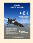
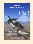
UTILITY
FLIGHT MANUAL
X-15-2/3
ADD-ON ROCKET AIRCRAFT
FOR FLIGHT SIMULATOR
Serial numbers: AF56-6671 & AF56-6672
(XLR-99 engine)
ENGLISH VERSION 1.0
Desktop commanders are responsible for
bringing this publication to the attention of
all flight simulator enthusiasts and X-15
fans cleared for operation of subject addon rocket aircraft.
Contains full product description and specifications, installation instructions, normal
procedures and check list.
Xtreme
Prototypes
www.xtremeprototypes.com
X-15 FOR FLIGHT SIMULATOR SERIES
TABLE OF CONTENTS
FOREWORD
Section
Section
Section
Section
Section
Section
I
II
III
IV
V
VI
4
INTRODUCTION AND PRODUCT DESCRIPTION
1-1
SOFTWARE INSTALLATION
2-1
AIRCRAFT DESCRIPTION AND SPECIFICATIONS
3-1
INSTRUMENT PANELS
4-1
NORMAL PROCEDURES AND CHECK LIST
5-1
CONDENSED PROCEDURES AND CHECK LIST
6-1
APPENDICES
Appendix 1:
QUICK-START PROCEDURES
A-1
Appendix 2:
INSTRUMENT READINGS
A-2
Appendix 3:
FS AIRCRAFT REFERENCE INFORMATION
A-3
Appendix 4: PRODUCT SPECIFICATIONS
A-4
Appendix 5: SELECTED INTERNET LINKS
A-5
Appendix 6: SELECTED BIBLIOGRAPHY
A-6
Appendix 7: OTHER X-15 FOR FLIGHT SIMULATOR PRODUCTS by Xtreme Prototypes
A-7
Xtreme Prototypes X-15-2/3 for Flight Simulator, Version 1.0 – Utility Flight Manual
3
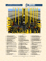
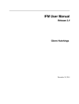
GENERAL ARRANGEMENT
X-15-3 (BALL NOSE, XLR-99 ENGINE,
WING-TIP PODS VERSION)
1
12
17
2
3
14
4
15
6
5
16
18
13
7
19
23
27
35
8
20
28
21
36
37
9 10
11
22
Figure 3-2
1. MOVABLE HORIZONTAL STABILIZER
2. BALLISTIC CONTROL SYSTEM ROCKETS (2,
ON BOTH WINGS)
3. UPPER SPEED BRAKE
4. MOVABLE UPPER VERTICAL STABILIZER
5. LIQUID OXYGEN TANK (FROST)
6. APU EXHAUST (2, LEFT AND RIGHT)
7. EQUIPMENT COMPARTMENT
8. CANOPY
9. PITOT HEAD
10. BALLISTIC CONTROL SYSTEM ROCKETS (8)
11. NACA/NORTRONICS BALL NOSE
12. WING-TIP POD (2, LEFT AND RIGHT)
13. TOP BUG-EYE CAMERA PORT
24
25
30
31
14. REAR LANDING GEAR SKID (2, ON BOTH
SIDES)
15. LOWER SPEED BRAKE
16. LOWER FIXED VERTICAL STABILIZER
(MOVABLE VENTRAL REMOVED)
17. WING (2, LEFT AND RIGHT)
18. SIDE FAIRING (2, LEFT AND RIGHT)
19. LOWER UHF ANTENNAS
20. EXTERNAL CANOPY EMERGENCY JETTISON
HANDLE ACCESS DOOR
21. NOSE LANDING GEAR DOOR
22. NOSE LANDING GEAR
23. VENTRAL BUG-EYE CAMERA PORT (2, ON
BOTH SIDES)
26
3
4
32
33
15
1
14
17
16
5
18
12
34
24. ENGINE TURBOPUMP EXHAUST
25. RESEARCH INSTRUMENTS
26. TAIL-CONE BOX
27. EJECTION SEAT
28. PILOT (FULL PRESSURE SUIT)
29. INSTRUMENT PANEL
30. LIQUID OXYGEN JETTISON PORT
31. XLR-99 ROCKET ENGINE
32. AMMONIA JETTISON PORT
33. HYDROGEN PEROXIDE JETTISON PORT
34. FLAP (2, LEFT AND RIGHT)
35. COCKPIT CAMERA
36. COCKPIT LIGHT
37. ENGINE TIMER (STOPWATCH)
6
23
13
7
19
8
28
21
Xtreme Prototypes X-15-2/3 for Flight Simulator Version 1.0 – Utility Flight Manual
3-5
22
10
29
11
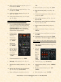
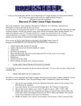
MAIN PANEL
WITH INERTIAL ALL-ATTITUDE FLIGHT
DATA SYSTEM AND XLR-99 ENGINE (X-15-2a)
* Gauges in gray do not perform any specific simulator function.
24 25
26 27
28 29 30 31
32 8
34 35 36 37 38 39 40 41 42 43 44 45 46 47 48
49
23
22
21
20
50
19
18
17
16
15
14
13
88
11
12
9
84
7
6
5
4
51
52
53
54
89
55
3 2 1
87 81 86 85 82
78 76 80 72 10 77 79 75 74 73 33 71 70 69 68 67 66 65 64 63
62 61 60 59
58
57 56
Figure 4-1
1.
2.
3.
4.
5.
6.
7.
8.
9.
10.
11.
12.
13.
14.
15.
16.
17.
18.
19.
20.
21.
22.
23.
24.
25.
26.
27.
28.
29.
AMMONIA JETTISON STOP SWITCH
H2O2 JETTISON STOP SWITCH
LIQUID OXYGEN JETTISON STOP SWITCH
H2O2 SOURCE AND PURGE PRESSURE GAUGE
DISPLAY/HIDE LEFT SIDE PANEL ICON
PROPELLANT TANK PRESSURE GAUGE
AUXILIARY LAUNCH SWITCH*
SIDE-SLIP INDICATOR
LANDING GEAR HANDLE
HELIUM RELEASE SELECTOR SWITCH
VENTRAL JETTISON BUTTON
PROPELLANT SOURCE PRESSURE GAUGE
FIRE-WARNING LIGHT
AMMONIA TANK PRESSURE-LOW CAUTION
LIGHT
ENGINE VIB MALFUNCTION CAUTION LIGHT
PROPELLANT EMERGENCY PRESS. SWITCH
TURBOPUMP OVERSPEED CAUTION LIGHT
LIQUID OXYGEN PRESSURE-LOW CAUTION
LIGHT
STAGE 2 IGNITION MALFUNCTION CAUTION
LIGHT
VALVE MALFUNCTION CAUTION LIGHT
IDLE-END CAUTION LIGHT
NO-DROP OR 23-SECOND CAUTION LIGHT
IGNITION-READY LIGHT
DISPLAY/HIDE LEFT WHITE CONSOLE ICON
DISPLAY/HIDE THROTTLE AND SPEED BRAKE
PANEL ICON
ALTIMETER
AIRSPEED/MACH INDICATOR
PILOT’S OXYGEN-LOW CAUTION LIGHT
FUEL QUANTITY GAUGE
30.
31.
32.
33.
34.
35.
36.
37.
38.
39.
40.
41.
42.
43.
44.
45.
46.
47.
48.
49.
50.
51.
52.
53.
54.
55.
56.
57.
58.
59.
ACCELEROMETER
ANGLE-OF-ATTACK INDICATOR
ATTITUDE INDICATOR
AZIMUTH/ADF INDICATOR
ENGINE TIMER (STOPWATCH)
NO. 1 APU SWITCH
PITCH ANGLE SET CONTROL
INERTIAL SPEED (VELOCITY) INDICATOR
INERTIAL HEIGH (ALTIMETER) INDICATOR
NO.1 APU H2O2 COMPARTMENT OVERHEAT
WARNING LIGHT
NO. 1 APU COMPARTMENT OVERHEAT CAUTION LIGHT
NO.1 GENERATOR-OUT LIGHT
DISPLAY/HIDE ICONS: COMPASS, MAP
NO. 1 GENERATOR AC VOLTMETER
MACHMETER
NO.1 GENERATOR SWITCH
NO. 2 GENERATOR SWITCH
EMERGENCY BATTERY SWITCH
NO. 2 GENERATOR-OUT LIGHT
HYDROGEN PEROXIDE TRANSFER SWITCH
NO.2 GENERATOR AC VOLTMETER
NO. 2 APU H2O2 COMPARTMENT OVERHEAT
WARNING LIGHT
NO. 2 APU COMPARTMENT CAUTION LIGHT
NO. 2 APU H2O2-LOW CAUTION LIGHT
NO.2 APU SWITCH
CANOPY INT. EMERGENCY JETTISON HANDLE
DISPLAY/HIDE RIGHT PANEL ICON
STABLE PLATFORM SWITCH
NO. 2 HYDRAULIC TEMPERATURE GAUGE
CABIN PRESSURE ALTIMETER
60.
61.
62.
63.
64.
65.
66.
67.
68.
69.
70.
71.
72.
73.
74.
75.
76.
77.
78.
79.
80.
81.
82.
83.
84.
85.
86.
87.
88.
89.
HYDRAULIC PRESSURE GAUGE
CABIN HELIUM SOURCE PRESSURE GAUGE
NO. 2 BALLISTIC CONTROL SWITCH
APU BEARING TEMPERATURE GAUGE
APU H2O2 TANK PRESSURE GAUGE
NO. 1 BALLISTIC CONTROL SWITCH
MIXING CHAMBER TEMPERATURE GAUGE
APU SOURCE PRESSURE GAUGE
NO.1 APU H2O2-LOW CAUTION LIGHT
NO.1 HYDRAULIC TEMPERATURE GAUGE
CLOCK
DISPLAY/HIDE CENTRAL PEDESTAL ICON
LIQUID OXYGEN BEARING TEMPERATURE
GAUGE
RATE-OF-ROLL INDICATOR
IGNITER IDLE SWITCH
H2O2 COMPARTMENT-HOT CAUTION LIGHT
CHAMBER & STAGE 2 IGNITER PRESS. GAUGE
TURBOPUMP IDLE BUTTON
ENGINE PRIME SWITCH
DISPLAY/HIDE GPS ICON
DISPLAY/HIDE ICONS: RADIO/ADF PANEL,
ATC WINDOW
ENGINE PRECOOL SWITCH
DISPLAY/HIDE KNEEBOARD ICON
NOT IN USE
PROPELLANT MANIFOLD PRESSURE GAUGE
FUEL LINE-LOW CAUTION LIGHT
H2O2 TANK AND ENGINE CONTROL LINE
PRESSURE GAUGE
ENGINE RESET BUTTON
ENGINE MASTER SWITCH
DISPLAY/HIDE SERVICE PANEL ICON
Xtreme Prototypes X-15-2/3 for Flight Simulator, Version 1.0 – Utility Flight Manual
4-2
OFF.
19. Mixing chamber temperature gauge [66, fig. 4-1, 4-2,
4-3; 61, fig. 4-4] – Check.
12. Ram-air lever [28, fig. 4-11; 15, fig. 4-12] – OPEN.
20. APU bearing temperature gauge [63, fig. 4-1, 4-2, 43; 62, fig. 4-4] – Check.
21. Cabin source pressure gauge [61, fig. 4-1, 4-2, 4-3;
59, fig. 4-4] – Check.
22. Cabin pressure altimeter [59, fig. 4-1, 4-2, 4-3; 60,
fig. 4-4] – Check.
Center pedestal (stability augmentation system panel, if
available, and research instrumentation panel):
1.
Click the DISPLAY/HIDE CENTER PEDESTAL
icon [71, fig 4-1, 4-2, 4-3, 4-4] at the center of the
main panel to display the center pedestal (or select
CENTER PEDESTAL from the “Instrument
Panel” menu, under the “View” menu of the main
Flight Simulator window menu bar).
2.
Undock and reposition the panel if
necessary.
3.
Pitch function
switch [32, fig. 411] – STDBY.
4.
13. Radar beacon switch [22, fig. 4-11; 13, fig. 4-12] –
OFF.
14. Instrumentation master power switch [10, fig. 4-11;
14, fig. 4-12] – OFF.
15. Stable platform instrument switch [21, fig. 4-11; 9,
fig. 4-12] – ON.
16. Ball nose power switch (if ball nose is installed) [9,
fig. 4-11; 5, fig. 4-12] – ON.
17. Engine vibration recorder switch [18, fig. 4-11] –
OFF.
18. Cockpit ram-air knob [17, fig. 4-11; 10, fig. 4-12] –
OFF (in).
19. DC voltmeter selector switch [20, fig. 4-11; 12, fig. 412] – BUS.
20. DC voltmeter [19, fig. 4-11; 11, fig. 4-12] – Check
(28-volt bus or 24-volt strain gauge or battery).
Center pedestal or main panel (MH-96 system control
panel on X-15-3):
Roll function
switch [31, fig. 411] – STDBY.
1.
Pitch, roll and yaw damper switches [1-3, fig. 4-14] –
OFF (DOWN).
2.
Pitch, roll
and yaw
gain selector
switches
[8-10, fig.
4-14] –
FIXED
GAIN
(DOWN).
3.
CSS switch [4, fig. 4-14] – OFF (DOWN).
4.
Auto-trim selector switch [5, fig. 4-14] – NORMAL
(DOWN).
10. Ball nose test button (if ball nose is installed) [25,
fig. 4-11; 6, fig. 4-12] – Check (normal).
5.
Reaction controls switch [6, fig. 4-14] – OFF
(DOWN).
11. Engine oscillograph record switch [11, fig. 4-11] –
6.
Roll trim knob [7, fig. 4-14] – CENTER.
5.
SAS test switch [7,
fig. 4-11] – Check
OFF (CENTER).
6.
Yar function
switch [6, fig. 4-11]
– STDBY.
7.
Yaw function switch [5, fig. 4-11] – STDBY.
8.
SAS caution (amber) lights (four) [1-4, fig. 4-11] –
Check ON.
9.
SAS gain selector knobs [8, 29-30, fig. 4-11] – Set to
LO.
Xtreme Prototypes X-15-2/3 for Flight Simulator, Version 1.0 – Utility Flight Manual
5-12
PRELAUNCH
6.
No. 2 generator out (amber) light [48, fig. 4-1, 4-2, 43; 47, fig 4-4] – Check OFF.
BEFORE COUNTDOWN
Before countdown, complete final cockpit check as follows:
1.
Ram-air lever [28, fig. 4-11; 15, fig.
4-12] – Check CLOSED.
2.
Ventral arming switch [3, fig. 4-7]
– Check ARM.
APUs:
When the APUs are operating, steam should be observed
coming out of the APU exhaust pipes.
1.
2.
3.
4.
5.
APU switch No. 1 [35, fig. 4-1, 4-2, 4-3; 67, fig. 4-4] –
ON. As APU No. 1 comes up to speed, hydraulic
pressure will increase and then stabilize at 3000 to
3500 psi.
No. 1 generator switch [45, fig. 4-1, 4-2, 4-3; 44, fig.
4-4] – Move No. 1 generator switch momentarily to
RESET, then to ON.
No. 1 generator out (amber) light [41, fig. 4-1, 4-2, 43; 42, fig. 4-4] – Check OFF.
APU switch No. 2 [54, fig. 4-1, 4-2, 4-3, 4-4] – ON.
As APU No. 2 comes up to speed, hydraulic pressure
will increase and then stabilize at 3000 to 3500 psi.
No. 2 generator switch [46, fig. 4-1, 4-2, 4-3; 49, fig.
4-4] – Move No. 2 generator switch momentarily to
RESET, then to ON.
7.
Stable platform power switch [57, fig. 4-1, 4-2, 4-3;
58, fig. 4-4; 9, fig. 4-7] – INT (up
position).
8.
Service panel external power
switch [24, fig. 4-5] – OFF.
9.
Service panel external power
(yellow) light [25, fig. 4-5] – Check
OFF.
10. No. 1 generator voltmeter [43, fig.
4-1, 4-2, 4-3; 45, fig. 4-4] – Check
(200 volts, internal).
11. No. 2 generator voltmeter [50, fig. 4-1, 4-2, 4-3; 45,
fig. 4-4] – Check (200 volts, internal).
12. Hydraulic pressure gauge [60, fig 4-1, 4-2, 4-3; 36,
fig. 4-4] – Check (both pointers, 3000 to 3500
psi).
13. DC voltmeter selector switch [20, fig. 4-11; 12, fig. 412] – Check BUS.
14. DC voltmeter [19, fig. 4-11; 11, fig. 4-12] – Check
(28 volts).
Xtreme Prototypes X-15-2/3 for Flight Simulator, Version 1.0 – Utility Flight Manual
5-16
NOTE: The prime can be stopped at any time by placing
the engine prime switch at STOP PRIME. This closes
the liquid oxygen and NH3 tank main propellant valves
and the H2O2 safety valve.
The manifold pressure will increase during engine operation and will vary according to the movement of the
throttle. Make sure that the throttle on your joystick is
set to its minimum position:
13. Chamber and stage 2 igniter pressure gauge [76, fig.
4-1, 4-2, 4-3; 28, fig 4-4] – Check (both pointers, 0
psi).
20. Move the throttle on your joystick to its maximum
(forward) position. Then pull the throttle back to
its minimum position.
14. Liquid oxygen bearing temperature gauge [72, fig. 41, 4-2, 4-3] – Check.
21. Telemeter and radar switches [13, 22, fig. 4-11; 16,
13, fig. 4-12] – Recheck.
15. H2O2 source and purge pressure gauge [4, fig. 4-1, 42, 4-3, 4-4] – Check (pointers 1 and 2, 3000 to
3900 psi).
22. Telemeter commutator motor switch [16, fig. 4-11;
17, fig. 4-12] – Check ON.
23. Communications – Check.
16. H2O2 tank and engine control line pressure gauge
[86, fig. 4-1, 4-2, 4-3; 79, fig. 4-4] – Check (both
pointers, 575 to 615 psi).
In the real world: Check communication with ground
station, carrier pilot, and chase pilots.
17. Propellant pump inlet pressure gauge [8, fig. 4-2, 43; 74, fig. 4-4] – Check (both pointers, 45 to 65
psi).
24. Ready-to-Launch switch [3, fig. 49; 82, fig. 4-2, 4-3; 76, fig. 4-4] –
ON.
18. Turbopump idle button
[77, fig. 4-1, 4-2, 4-3; 78,
fig. 4-4] – Push once. This
will start the engine turbopump and hot exhaust
gas will be emitted at the
back of the aircraft.
In the real world: Verbally check with
carrier pilot and launch operator that
the Ready-to-Launch light is on.
25. Ready-to-Launch (green) light on Service Panel [11,
fig. 4-5] – Check ON.
19. Propellant manifold pressure gauge [84, fig. 4-1, 4-2,
4-3; 72, fig. 4-4] – Check (both pointers, 300 to
450 psi).
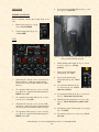
Operation of igniter idle is limited to 30 seconds. When 7
seconds remain of the normal igniter idle phase, the nodrop or 23-second (amber)
caution light [22, fig. 4-1, 4-2,
4-3; 21, fig. 4-4] will come ON.
With the no-drop or 23-second
(amber) caution light on, the
pilot must terminate the igniter idle phase – by moving
the engine prime switch to
STOP PRIME – or continue
on to the launch phase.
Turbopump operation.
In the real world: The igniter
idle phase must be terminated
immediately if the idle-end
(amber) caution light [21, fig. 4-1, 4-2, 4-3; 20, fig. 4-3]
Xtreme Prototypes X-15-2/3 for Flight Simulator, Version 1.0 – Utility Flight Manual
5-20
comes on, as damage to the engine chamber will occur
because of insufficient cooling.
BALLISTIC CONTROL AND REACTION AUGMENTATION SYSTEM OPERATION
26. Igniter idle switch [74, fig. 4-1, 4-2, 4-3; 75, fig. 4-4]
– IGNITER.
Since many missions will involve flight at altitudes where
control surfaces are ineffective and where ballistic control system operation will be required to maintain airplane attitude, the ballistic control system should be
turned on before launch. The reaction augmentation system (RAS)* should be turned on as soon as possible after
engine burnout. To turn on the ballistic control and reaction augmentation systems, proceed as follows:
When the igniter idle switch is placed to IGNITER, the
ignition-ready light [23, fig. 4-1, 4-2, 4-3; 22, fig. 4-4] goes
out for 2 seconds while the engine is purged with helium
and the igniter spark plugs are energized. When this
phase is completed, the ignition-ready light comes on
again.
27. Chamber and stage 2 igniter pressure gauge [76, fig.
4-1, 4-2, 4-3; 28, fig 4-4] – Check (small pointer,
150 psi in about 5
seconds, when stage
2 is ignited). Flames
should be observed
inside the rocket engine bell (nozzle) as
stage 1 and stage 2 are
ignited.
1.
No. 1 ballistic control switch [65, fig. 4-1, 4-2, 4-3;
40, fig. 4-4] – ON.
2.
No. 2 ballistic control switch [62, fig. 4-1, 4-2, 4-3;
50, fig. 4-43] – ON.
3.
RAS function switches (X-15-2 aircraft only*) [1-3,
fig. 4-13] – ENGAGE.
4.
RAS-out (amber) light (X-15-2 aircraft only*) [42,
fig. 4-2] – OUT (OFF).
The main chamber and
stage 2 igniter pressure will increase during engine operation and will vary according to the movement of the
throttle.
Ready to launch! In the real world: Countdown by carrier pilot.
*: There is no RAS installed in the X-15-2 equipped with
the NACA vane-type boom nose. On the X-15-2 equipped
with the NACA/Nortronics ball nose, the RAS panel is
available as a separate panel, under the “Views/
Instrument Panel” menu of
the main FS window.
5.
Igniter idle phase.
MH-96 system reaction controls switch
(X-15-3 aircraft only)
[6, fig. 4-14] – ON
(UP). Check that the
MH-96 system indicator (amber) lights [90,
fig. 4-3; 85, fig. 4-4]
are on.
Xtreme Prototypes X-15-2/3 for Flight Simulator, Version 1.0 – Utility Flight Manual
5-21
4.
Propellant (helium) source pressure gauge [12, fig.
4-1, 4-2, 4-3; 13, fig. 4-4] – Check (3300 to 3900
psi).
5.
H2O2 source and purge pressure gauge [4, fig. 4-1, 42, 4-3, 4-4] – Check (both pointers, 3300 to 3900
psi).
6.
Propellant tank pressure gauge [6, fig. 4-1, 4-2, 4-3;
81, fig. 4-4] – Check ("L" pointer, 45 to 65 psi;
"A" pointer, 45 to 65 psi).
vice panel;
Chamber pressure will reach rated values;
Thrust chamber will emit a great deal of noise;
Flames and exhaust gases (smoke, steam) will be
seen at the back of the airplane.
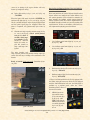
ENGINE THRUST CONTROL
7.
H2O2 tank and engine control line pressure gauge
[86, fig. 4-1, 4-2, 4-3; 79, fig. 4-4] – Check (both
pointers, 575 to 615 psi).
Engine thrust is controlled
by movement of the throttle between 50% and 100%
thrust. Engine response to
throttle movement is very
rapid, 50% to 100% in
approximately 1.5 seconds.
Remember that combustion in the main thrust
chamber of the XLR-99
engine on the X-15 for Flight Simulator will occur almost
instantaneously when the throttle lever [1, fig. 4-9] is
moved from OFF to START 50%.
NORMAL OPERATING CONDITIONS
The following conditions accompany normal rocket engine
operation (see appendix 2 for more details):
XLR-99 engine:
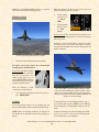
X-15-3 in flight.
NORMAL INDICATIONS DURING START
1.
Propellant source pressure gauge [12, fig. 4-1, 4-2, 43; 13, fig. 4-4] – 3200-3800 psi.
2.
H2O2 source and purge pressure gauge [4, fig. 4-1, 42, 4-3, 4-4] – 3000 psi, gradually decreasing
(both pointers).
3.
Propellant tank pressure gauge [6, fig. 4-1, 4-2, 4-3;
81, fig. 4-4] – 45 to 53 psi (both pointers).
4.
Propellant pump inlet pressure gauge [8, fig. 4-2, 43; 74, fig. 4-4] – “L” pointer, 40 to 70 psi; “A”
pointer, 40 to 55 psi.
5.
APU H2O2 tank pressure gauge [64, fig. 4-1, 4-2, 4-3;
66, fig. 4-4] – 550 to 610 psi (both pointers).
6.
Cabin helium source pressure gauge [61, fig. 4-1, 42, 4-3; 59, fig. 4-4] – 1000 to 3400 psi.
7.
Hydraulic temperature gauges [58, 69, fig. 4-1, 4-2,
4-3] – 0° C to 150° C.
When the thrust chamber or chambers are fired, the following indications will be evident:
Turbine whine;
Turbine exhaust steam will be seen at the back of
the aircraft;
Liquid oxygen and ammonia will automatically stop
bleeding overboard (as observed during prime);
Liquid oxygen and ammonia manifold pressure will
rise to rated values;
Igniters will be operating;
Chamber pressure will rise to a point where the
igniters cease firing and chamber pressure will be
shown on the indicator gauge;
Airplane propellants will be consumed at a very
high rate, as can be observed on the volume gauges
[1-3, fig. 4-5] on the X-15 for Flight Simulator ser-
Xtreme Prototypes X-15-2/3 for Flight Simulator, Version 1.0 – Utility Flight Manual
5-25
opened, closed and adjusted using the speed brake
handle on the throttle and speed brake side panel).
2.
10] – JETTISON. Fuel
jettison will be conducted
concurrently on all three
systems (liquid oxygen,
ammonia, and hydrogen
peroxide).
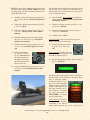
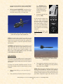
Pull the joystick SMOOTHLY to perform a 5-G to
7-G pullout to level flight at about 70,000 to 60,000
feet, after reentry (see fig. 5-1 on page 5-22).
3.
Jettison stop switches [4-6,
fig. 4-6] – JETT.
In the spot plane exterior view,
check for vapor emitting from
the jettison ports, at the back of
the X-15 aircraft. Propellant
tank volume gauges [1-3, fig. 45], on the X-15 for Flight Simulator service panel, can also give a
clear indication of the fuel being
jettisoned.
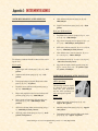
X-15-3 during her descent and about to perform a 5G
pullout to level flight at about 65,000 feet.
In the real world: Have chase
pilots verify that fuel is jettisoning.
NOTE: The speed brakes on the X-15 aircraft were not
designed for use as a low-speed drag device. Their design
function was to provide the necessary drag conditions for
control of the airplane at supersonic speeds and relatively
high altitudes.
*CAUTION: Remember that the X-15 possesses a very
low lift-drag ratio. After the engine burned out, the aircraft would come down fast and steep. Because of the
high rate of descent and the reduced stability at low
Mach numbers, the speed brakes are not to be used
at full deflection below Mach 1.5.
FUEL JETTISON
Before landing, the remaining propellants are dumped
overboard through the jettison ports on the X-15-3 for
Flight Simulator.
While approaching the landing site, the remaining propellants must be jettisoned from the X-15 to minimize fire or
explosion hazard upon landing and to lower the weight of
the aircraft.
4.
To jettison the remaining propellants from the X-15 airplane before landing or after an aborted launch, proceed
as follows:
1.
Source pressure [12, fig. 4-1, 4-2, 4-3; 13, fig. 4-4] –
Check.
2.
Vent, pressurize, and jettison control lever [3, fig. 4-
Vent, pressurize, and jettison control lever [3, fig. 410] – VENT. After propellants have been jettisoned,
move control lever to VENT.
NOTE: The liquid oxygen and ammonia jettison ports are
the long tubes protruding at the back of the airplane’s
side fairings (each side of the engine compartment). The
hydrogen peroxide jettison port is located inside the lower
speed brake compartment (right side). Because of some
Xtreme Prototypes X-15-2/3 for Flight Simulator, Version 1.0 – Utility Flight Manual
5-27
limitations of the FS2004 platform, there is no special
effect associated with the APU H2O2 jettison.
When the altimeter [19, fig. 4-1; 26, fig 4-2; 25, fig. 4-3]
indicates 5000 feet, proceed as follows:
1.
Ventral arming
switch [3, fig. 47] – Check
ARM.
2.
Ventral jettison
button [2, fig. 46] – Push
(once).
BEFORE LANDING
In the real world: The ventral should be jettisoned at an
altitude of about 5000 feet and at a minimum of 1500 feet
above the ground.
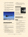
Pushing the ventral jettison button actually fires explosive bolts to release the ventral. Note that the ventral is
also jettisoned automatically when the landing gear and
skids are deployed.
X-15-3 approaching Edwards Air Force Base.
1.
Check all controls and instruments for landing.
See figure 5-2 on page 5-29 for the recommended
landing pattern and procedures.
In the real world: Before landing
and in no case above 17,000 feet,
move the vent, pressurize, and
jettison control lever [3, fig. 410] to PRESSURIZE, to prevent
sand and dust from entering the
airplane propellant system.
When the altitude is under
17,000 feet, proceed as follows:
1.
Vent, pressurize, and jettison control lever [3, fig. 410] – PRESSURIZE.
LANDING
The ventral rudder is jettisoned before landing to make
room for the rear landing skids. In the real world, a parachute will prevent the rudder from being damaged upon
landing on the ground. The rudder would be recovered and
reused. (X-15-1 shown here)
To provide ground clearance for the landing gear, the
lower ventral (rudder) must be jettisoned before landing.
To extend the flaps, turn the wing flap switch [1, fig. 410] on the left white console to DWN or use the “F8” key
on your keyboard (or the appropriate button on your joystick).
NOTE: Under normal flight conditions, the ventral rudder should not be jettisoned except during landing approach.
To lower the landing gear, click the landing gear handle
[9, fig. 4-1, 4-2, 4-3, 4-4; 1, fig. 4-6] on the left side panel
or use the “G” key on your keyboard.
Xtreme Prototypes X-15-2/3 for Flight Simulator, Version 1.0 – Utility Flight Manual
5-28
Before landing, on the downwind leg of the landing
pattern, but in no case above 17,000 feet above sea
level, move the vent, pressurize and jettison control
lever to PRESSURIZE to prevent sand from entering the
airplane propellant system during landing.
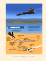
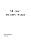
LANDING PATTERN
To ensure safe recovery, the ventral section of the vertical stabilizer (rudder) should be jettisoned at least 1500
feet above the ground.
ALTERNATE HIGH KEY POINT 22,500 FEET,
300 KNOTS, GEAR AND FLAPS UP
ROLL INTO 30-DEGREE BANKED TURN
ALTERNATE LOW KEY POINT
11,500 FEET AT 180 DEGREES
(93 SECONDS)
HIGH KEY POINT
15,200 FEET,
300 KNOTS, GEAR
AND FLAPS UP,
ROLL INTO 45DEGREE BANKED
TURN
(183 SECONDS)
16,700 FEET
(137 SECONDS)
LOW KEY POINT
8700 FEET AT
180 DEGREES (58 SECONDS)
106 SECONDS)
ALTERNATE 90-DEGREE POINT
7100 FEET, 240 KNOTS,
90 DEGREES FROM
RUNWAY (54 SECONDS)
90-DEGREE POINT
5800 FEET
240 KNOTS, 90 DEGREES FROM
RUNWAY
(36 SECONDS)
VENTRAL JETTISON
5000 FEET
ROLL OUT OF TURN
3200 FEET, 240 KNOTS
LOWER FLAPS
VENTRAL JETTISON
5000 FEET
(15.6 SECONDS)
11,900 FEET
(82 SECONDS)
FLARE COMPLETED
2200 FEET
174 KNOTS
TOUCHDOWN
174 KNOTS
(0 SECONDS)
BEGIN 1.3G PULL-OUT
2700 FEET, 240 KNOTS
DROP GEAR
(10.6 SECONDS)
Figure 5-2
Xtreme Prototypes X-15-2/3 for Flight Simulator, Version 1.0 – Utility Flight Manual
5-29
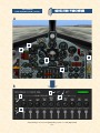
QUICK-START PROCEDURES
XLR-99 ENGINE
(LIGHT BLUE-GRAY PANEL, TYPICAL)
A
5
4
1
2
3
B
8
6
9
7
Xtreme Prototypes X-15-2/3 for Flight Simulator, Version 1.0 – Utility Flight Manual
A1-5
Appendix 2: INSTRUMENT READINGS
INSTRUMENT READINGS AFTER SERVICING
9.
Cabin helium tank pressure gauge [12, fig. 4-5] –
3200-3800 psi.
10. Liquid N2 tank volume gauge [13, fig. 4-5] – 25-30
gallons.
Main panel (XLR-99 engine):
1.
Propellant source pressure gauge [12, fig. 4-1, 4-2, 43; 13, fig. 4-4] – 3200-3800 psi.
2.
H2O2 source and purge pressure gauge [4, fig. 4-1, 42, 4-3, 4-4] – 3200-3800 psi, both pointers.
3.
APU source pressure gauge [67, fig. 4-1, 4-2, 4-3; 65,
fig. 4-4] – 3200-3800 psi, both pointers.
4.
Cabin helium source pressure gauge [61, fig. 4-1, 42, 4-3; 59, fig. 4-4] – 1000 to 3400 psi.
The following conditions should be observed after servicing the X-15:
5.
AC voltmeters [43, 50, fig. 4-1, 4-2, 4-3; 45, fig. 4-4]
– 200 volts (external power).
Service panel:
6.
H2O2 tank and engine control pressure gauge [86,
fig. 4-1, 4-2, 4-3; 79, fig. 4-4] – “T” pointer, 0 psi;
“C” pointer, 575-600 psi.
1.
Liquid oxygen tank volume gauge [1, fig. 4-5] – 1017
gallons.
2.
Ammonia tank volume gauge [2, fig. 4-5] – 1445
gallons.
INSTRUMENT READINGS AFTER PROPELLANT
SYSTEM PRESSURIZATION
3.
Turbopump hydrogen peroxide (H2O2) tank volume
gauge [3, fig. 4-5] – 78 gallons.
(APUs operating)
4.
Propellant source (helium) tank pressure gauge [4,
fig. 4-5] – 3200-3800 psi.
5.
Engine and propellant control source (helium) tank
pressure gauge [5, fig. 4-5] – 3200-3800 psi.
6.
Engine purge and emergency (helium) tanks pressure gauge [7, fig. 4-5] – 3200-3800 psi, both
pointers.
The following conditions should
be observed after propellant
tanks have been pressurized
and the APUs operating, but
before the engine is ignited:
Service panel:
1.
Liquid oxygen tank volume gauge [1, fig. 4-5] –
Approx. 1017 gallons.
7.
APU source (helium) tanks pressure gauge [9, fig. 45] – 3200-3800 psi, both pointers.
2.
Ammonia tank volume gauge [2, fig. 4-5] – Approx.
1445 gallons.
8.
APU H2O2 tanks volume gauge [10, fig. 4-5] – 60-75
gallons, both pointers.
3.
Turbopump hydrogen peroxide (H2O2) tank volume
gauge [3, fig. 4-5] – Approx. 78 gallons.
Xtreme Prototypes X-15-2/3 for Flight Simulator, Version 1.0 – Utility Flight Manual
A2-1
Xtreme Prototypes X-15-2/3 for Flight Simulator, Version 1.0 – Utility Flight Manual (English). Copyright © 2007 by Xtreme
Prototypes, Inc. The software and the present manual are protected by international copyright laws. Please do not make unauthorized
copies of the software and/or its related components and documentation, including the present user manual. No part of this document
may be reproduced or redistributed in any form or by any means without the written permission of the publisher. All images in this
document are actual screenshots of the Xtreme Prototypes X-15-1, X-15-2/3 and X-15A-2 add-on rocket aircraft for Flight Simulator,
taken in the Microsoft® Flight Simulator 2004 and Flight Simulator X game environments, except where otherwise noted. Microsoft,
Microsoft Flight Simulator, Windows and DirectX are either registered trademarks or trademarks of Microsoft Corporation. Other company or product names mentioned herein may be trademarks or registered trademarks of their respective owners. Software features and
manual contents are subject to change without notice.
Portions of this manual have been inspired or adapted from the original real-world X-15 utility flight manuals published during the
1950s and 1960s by the U.S. Air Force and North American Aviation. NASA and AFFTC photos have been used in some sections for
comparison and illustration purposes only and are the property of their respective owners as credited. Xtreme Prototypes is not affiliated
with NASA, North American Aviation (Boeing), the U.S. Air Force, or any other company, entity or government organization related to
the X-15 research program. This product is neither sponsored nor endorsed by NASA.
Xtreme
Prototypes
www.xtremeprototypes.com
Xtreme Prototypes, Inc.
P.O. Box 64, Station Place du Parc
Montreal (QC), CANADA
H2X 4A3
Produced with the financial participation of
Administrator of
The Canada New Media Fund
funded by the
Department of Canadian Heritage