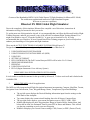
1
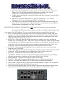
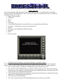
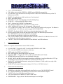
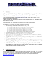
®
Creators of the Bombardier BD700 1A10 Global Express™ Flight Simulator for Microsoft FS 2004®,
The worlds most sophisticated interactive Flight Simulator Program.
Welcome to your new experience,
Bluesteel FS 2004 Global Flight Simulator
Due to the complexity of this simulator, Bluesteel has compiled a set of directions, instructions &
information to help you become the best you can be.
To get the most out of this particular Aircraft, it is recommended that you follow the Microsoft built in Flight
Training Programs, and also get yourself a copy of the official Government Flight Training Manual. You
might even include a copy of: “From the Ground Up.” A great way to learn how to fly. It is also
recommended that you consider a 30 hour Ground school Pilot Training program at your local Polytech to
enhance your knowledge of Navigation and flight situations.
These are the ACTIVE FUNCTIONS AVAILABLE IN FS2004 Global Express™
Designed and assembled for your enjoyment by: Jean-Marie & Ian of Bluesteel. ®
1.
2.
3.
4.
5.
6.
7.
8.
9.
1.
USING MSFS 2004 FLIGHT PLANNER
USING THE MULTI-FUNCTION DISPLAY (MFD)
USING GPS
SETTING AUTOPILOT
PFD CONTROLLER (The Full Version Honeywell PFD will be in the Ver 2.0 Later)
SIMICONS INFORMATION
PEDESTAL
USING FSNAVIGATOR
EICAS (Engine Instrument Crew Advisory System)
USING MSFS 2004 INTEGRATED FLIGHT PLANNER:
It is advisable to read the documents for this provided by Microsoft, ™ it does work well and is linked to the
GARMIN GPS
2.
USING THE MFD with all its applications:
The MFD is a fully integrated total Flight Navigation Instrument incorporating, Compass, Map/Plan, Terrain,
Navigation Source information, Time, Waypoint Range, Idents, Temperatures, Speed and Headings
•
•
•
•
•
The top left corner displays the Desired Heading information input from the settings on the
HDG knob of the Autopilot..
Top center displays the current aircraft heading above the 90 degree Compass Rose.
The top right corner displays your current Navigation sources, ADF1, VOR1, GPS1.
Middle right displays the next Waypoint data, Range in Nautical Miles, Station Ident, And
below that in white, the Estimated Time En-route ETE in Hours and Minutes. This will tell
you the time remaining to reach your next Waypoint.
Middle left displays your Current Course settings. CRS (Course) or DTK ( Desired Track).
•
•
•
•
®
Below that is the Total Flight time readout copied in real time from the system clock. ET,
Elapsed Time. This also displays additional functions as provided by the Aircraft
Chronometer, including Simulation speed, Stop Watch features etc.
The Blue frame center bottom is currently for display only and is called the Vertical Profile, it
is non-functional.
Right side Lower screen displays the SAT ‘Static Air Temperature’, TAT ’Total Air
Temperature’, TAS ‘True Air Speed’, and GSDP ‘ Ground Speed’.
The center shows an aircraft Icon which represents you, the aircraft, and the mid range 180
degree ARC is the mid point of the range from aircraft to visible horizon, at each end there is
a digital readout corresponding to your Map View Range.
MULTIFUNCTION DISPLAY CONTROLLER (“MFD” on the PFD controller next to the Autopilot.)
By touching the MFD button with your mouse, you will see the MFD Controller appear in the
lower portion of the MFD Indicator. There are several functions that may controlled from this panel.
• HUD – Controls the HUD pop-up panel which can be viewed from inside the cockpit. It has been
aligned to see the horizon when parked level on the ground. The Button on the left of the HUD will
toggle the screen On/Off, while the Track Indicator must be toggled by touchimg part of the upper
Frame of the HUD combiner (Glass Viewer).
• MAP/PLAN – Will toggle from Map Mode which shows the compass rose, range, Heading and
Heading bug, Track drift bug, VOR’s, NDB,s WP,s Airports, & Flight Plan with the Aircraft heading
always being vertical to Plan Mode which hides the Compass rose, heading bug, Track drift bug, but
returns with a full circle range line and the screen and map are always pointing True North. Your
aircraft Icon will relocate and point in the direction of the Flight Plan relative to North.
• FLT PLAN – Will pop-up the MS Flight Plan Viewer so that you may view your exact location
during any part of your flight.
• TERR – Will Toggle between Normal Mode and Terrain Mode, showing a full map with relief and in
living color. All the relevant data from your flight plan are visible in this mode as well.
• NAV/APT – Unclutters the MFD, removes NDB,s VOR,s APT,s etc.
• UP-ARROW – Will Zoom you closer to the ground for higher resolution, and the range markings
will show you the range or resolution you have chosen. From 5 NM to 500 NM.
• DOWN-ARROW – Will Zoom your range out to the 500 NM range.
• NAV/GPS – Will toggle between standard Navigation sources and GPS navigation Mode.
• GPS ON – Will toggle the GARMIN GPS 500 Pop-Up with very detailed functionality.
• STBY COMP – Toggles the Pop-Up Panel with the Standby Magnetic Compass. This will appear in
the top right of the screen near the Windshield center post.
• There are some other features which are in the works for the future, and the mouse will detect these
points. They are non-functional and will not cause any problems even if you click on them.
HUD
MAP
PLAN
FLT
PLAN
NAV
GPS
GPS
ON
STBY
COMP
TERR
NAV
APT
®
3.
USING THE GPS.
This selected from the 'GPS ON' button on the MFD Controller. This is a complicated device and fully
integrated with the MS Flight Planner. Nine active buttons on the lower panel will provide you with all the
data options you will ever need.
• Range Zoom In and Out.
• GPS Direct.
• Menu.
• Enter.
• Clear data.
• 5 Point CRSR Knob and Arrows which allows you to toggle Pages within Pages.
• Procedures – which allows you to set up an approach etc.
• Terrain
• FPL Shows your Flight Plan in FMS type format.
• Messages.
• OBS.
• Nearest Airports
GARMIN GPS 500
SUPPLIED BY MICROSOFT
4.
SETTING THE AUTOPILOT - FLIGHT GUIDANCE CONTROL PANEL:
No effort has been spared to provide you with the most complete and accurate function of the Autopilot,
however, there are still 2 buttons that are idle, and one of those has been used for a secondary function.
• 'AP'- Far right of panel, AUTOPILOT COMMAND toggles ON/OFF or Key (z).
• 'YD'- Sets the YAW DAMPER. Must be on whenever the Autopilot is in use. Auto-select when the
Hydraulics switch is engaged. It is normally driven from the Inertial Reference System but since that
is not available, I have subsidized the Hydraulics.
• 'CPL'- Dummy button displays the autopilot is coupled to the Left Side and is switched directly from
the Battery bus when the battery Master is ON.
• 'ALT'- Selects ALTITUDE HOLD.
• 'ALT SET'- Sets the Desired ALTITUDE displayed above the ALT tape on the PFD.
®
•
•
•
•
•
•
•
•
•
•
•
•
•
•
•
'LVL'- ATTITUDE HOLD.
'VS'- Allows you to set the VERTICAL SPEED and will HOLD automatically.
'PITCH Wheel'- Sets the Desired Vertical Speed with a DIGITAL readout near the top of the VS
Indicator on the PFD.
'BANK'- No application available at this time. Non-functional.
'HDG'- HEADING HOLD.
'HDG SET'- Sets the desired heading on all the Heading Bugs.
PUSH SET – will zoom the HDG Bug to North.
'NAV'- Locks to NAV SOURCE. (when tuned).
'BC'- 'BACK COURSE' Locks to Nav Source. (When tuned).
'APR'- 'APPROACH' Locks to ILS for Approach. (When tuned).
'FLC'- Flight Level Change. This is a VNAV feature, and not available in this program. The Button is
now RE-Named ‘A/T’ and is now used to toggle 'AUTO-THROTTLE'.
'SPD SET'- Pre-Sets the KIAS / MACH seen above the Speed tape on the PFD.
KIAS or MACH hold is on the left and right of the PUSH CHG below the Speed set Knob.
Note: SPD HOLD is only active when A/T is set engaged.
Note: Actual Aircraft Mach is visible below the Speed tape.
'FD'- FLIGHT DIRECTOR COMMAND BARS, sometimes called FLY-UP BARS. Also sets 'LVL'
as default when other Nav Sources are not set.
'CRS SET'- Sets the COURSE HEADING on the HSI/ARC and DTK indicators.
PFD CONTROLLER:
5.
There are 5 separate function buttons on the PFD Controller.
•
•
•
•
•
•
•
•
•
Left side 'BRG ◊' Toggles the ADF 1 needle on the PFD HSI in ARC Mode
'V/L' is for the VOR/ILS select. Inactive at this time.
'MFD' toggles the MFD Controller Panel.
'HSI'. Will toggle the HSI on the PFD to ARC Mode.
Right side ‘BRG ○’ Toggles the VOR 1 needle on the PFD HIS in ARC Mode.
MINIMUMS Knob and Switch are non-functional at this time.
‘BARO’ (In HG and MB) Switch toggle from Inches to Millibars, viewed just below the ALT Tape
on the PFD, but not properly functional. This will be solved with Ver 2.0.
'BARO SET' will adjust the Barometric setting for the Altimeters. Visible at the lower edge of the
Altitude tape on the PFD.
PUSH SET will zoom the Barometric setting to 29.92 in. or 1.013 Mb. Just try it.
SIMICONS INFORMATION:
6.
•
•
•
•
•
TRIMS Pop-up the Stab, Aileron and Rudder trim Panel over top of the WARNINGS panel.
ECU. Pop-up THROTTLE QUADRANT Icon-selects the Center Pedestal complete.
CLOCK Icon-selects Fully Functional Chronometer.
ATC Icon-selects ON-SCREEN ATC DATA with Voice.
KNEEBOARD – Pop-up for the Checklist and notepad to use in flight.
®
7.
PEDESTAL:
1. Here you will find the Semi-functional FMC to replace the FMS-CDU it was not written for the Global
Express, but does work quite well with sound and callouts for T/O Config. An FSUIPC independent version
of this Instrument is available from: http://www.Projectmagenta.com.
2. FS Navigator Flight Planner Selector Buttons; 'HOLD', 'M1/M2', 'PLAN', 'NEXT', 'PREV". These
functions are explained in the Section 8.
3. Below that is the 'RDU' Radio Display Unit. Which is fully integrated with the ATC Function, but can be
tuned manually if required.
Aileron and Rudder Trim Switches have been deleted (If you saw the layout for FS2002)
The Right half of this panel has been slightly modified for functionality.
1. Slat/Flap Selector (all functions controlled from (F5, F6, F7, F8)
• Key 1 (F7) sets the Slats to out. No movement of the selector handle)
• Key 2 (F7) sets FLAPS to 6 degrees. (Handle moves to 6 deg)
• Key 3 (F7) sets FLAPS to 15 degrees. (Handle moves to 15 deg)
• Key 4 (F7) sets FLAPS to 25 degrees. (Handle moves to 25 deg)
• Key 5 (F7) sets FLAPS to 30 degrees (DUMP) (handle moves to 30 deg)
2. LIFT/DUMP AUTO is the AutoSPLR Controller. Can be set from 0 to 100%
3. SPOILER LEVER can be infinitely adjusted or use (/) to toggle Max/Off.
4. GEAR selector Raises/Lowers the Undercarriage. Indicators are located on the EICAS. (DU No3),
showing UP/Locked, Travel, & DN Locked.
5. AUTOBRAKE: Be set to assist you during a landing operation. Required to be set to MAX for T/O
Config.
6. L/R Throttles With REVers Thrust capability.
7. ENG. START/CUTOFF Switches. Throttles will Auto set Above Idle during spool up when starting.
There are two ENG. Start Buttons located on the Overhead panel. The Fuel Cut Off switches must be
set on/up before the Engines will start.
8. AUTO-THROTTLE: A very useful tool when flying long range. It must be set before the SPD
HOLD function will operate. Once the A/T switch is engaged, the SPD HOLD must be set manually
on the Autopilot Panel where the name ‘PUSH CHG’.
8.
USING FSNAVIGATOR:
First you will need to purchase a copy of FSNavigator, which is compatible with FS2004. Ver. 4.6 or higher.
You will also need FSNavDBC, which is the database with all the SIDS, STARS, VOR, and AIRWAYS.
This comes as part of the original download from FSNavigator. These are updated monthly from
http://www.FSNavigator.com.
®
This Program does not interface with the GPS, but does integrate with the VOR/ILS MFD systems in
FS2004. Select the (F9) key to set up your flight plan. On the FMS located on the Pedestal (Throttle
Quadrant Icon), You will find the buttons to make selections for your FMS function of your FSNavigator
Flight Plan:
•
•
•
•
•
'PLAN'- Will toggle the feature ON/OFF.
'M1 / M2"- selects one of the 2 working modes of the FMS explained in the Help file for the product.
'HOLD'- will allow you to fly a holding pattern that you have previously programmed into the flight
plan.
'NEXT'- Will skip to the next waypoint.
'PREV'- Will double back to the previous waypoint.
It is easy to use this FMS feature in the inserted minimized window mode.
It also allows you to skip through, 'MAP', 'PLAN' & 'FMS', freely to check on your data.
The airport information in the 'MAP Mode' can provide you with the same information as Approach Plates.
You will need to read and understand the entire operation of FSNavigator before you can use it to your best
advantage
9.
EICAS:
This is the information nerve center of the Aircraft. This a Primary display and is powered from three
different sources.
• The Essential Battery Bus
• The Battery Direct Bus
• The Essential TRUE DC Bus 1.
All the data on this screen is collected from all parts of the aircraft and sorted via Data Acquisition Units and
analyzed then fed to the Integrated Avionics Computers which further analyses the data and sends it to the
Various display units. In the event of a piece of faulty data, it is sent to the Fault Warning Computer which
stores the data and decides what action to be taken then via the CAS Message box on the EICAS, lets the
Aircrew know that they have a problem.
ENGINE GAUGES: Have been created with fully functional Digital and analogue readouts,
EPR. ENGINE POWER RESERVE. Gauges.
FAN % RPM (N1) Gauges.
ITT (Inter Turbine Temp.) Gauges.
Digital read outs: N2 Turbine RPM.
FF (Fuel Flow) % PPH.
Oil Temp. And Oil Pressure Digital read out.
TOTAL FUEL Remaining in LBS. (Full is 444702 lbs) each wing holds 14444 lbs and the tail, 5359 lbs.
At the top right of this Display unit, is the Fault Warning Message Box.
This usually is in the form of a list, showing the most recent message at the top of any of the four type
sections. Since I have not had the time to create such a program, and it would be extensive, there are over
300 data callouts for this function; I have used several devices already available to give some indication of
®
standard failures or advisories you might expect from this type of program. I shall create the correct program
for this as time goes on. (Please be patient)
By way of explanation, the 4 categories of failure would be:
RED - WARNING Message. A Primary Concern. e.g. Engine Failure.
AMBER - CAUTION Message. A Precautionary Concern. e.g. Icing.
CYAN - ADVISORY Message - Low Priority. e.g. Auto Throttle Fail.
WHITE - STATUS Message - Normal Function Active: e.g. Fuel Transfer.
Below that is the GEAR Indication: there are 3 conditions for these indicators:
Green Square= Down & locked.
Red/Black Stripe=Gear Unlocked or in Travel.
'UP'= Gear is UP and Locked.
TRIMS:
Green Light, Spoilers active/extended. Shown as DASHED Lines in the Wing Form Graphic
Green Lights Leading Edge Slats Visible when extended, with the words IN or OUT to the right.
Green L and R Flap Indications slide down to the preset Stop positions. With Digital readout in Degrees
ELEVATOR PITCH ANGLE is shown with a Vertical line & Arrow also Digital read out.
AILERON TRIM is shown with a Green rotating needle.
RUDDER TRIM is shown with a lateral graduated line and arrow.
Display Unit No4: is known as the Synoptic Page, and displays various system data such as BLEED AIR
Management, DC POWER Distribution, AC POWER Distribution, All FLIGHT CONTROLS,
HYDRAULIC PUMPS and Flow lines, Valves, Pressures. FUEL SYSTEM Status, Pumps, Flow lines,
Valves, Qty. CABIN & COCKPIT AIR CONDITIONING Air Cycle unit status/Temps etc. and finally the
Partial Page shown here, which is the Default Page: It displays: Cabin/Cockpit Temp. Pressurization/Outflow
valve status, APU Data, OXYGEN QTY and PRESSURE. BRAKE TEMPERATURES and Last, All EXIT
Doors and Hatches Status.
With NUM LOCK Selected, and in the Cockpit View Mode, it is possible to scan the various Views around
you.
7= 45deg Left Fwd View.
4= 90deg Left View.
9= 45deg Right View.
6= 90deg Right View.
2= Cabin View (This is an actual Cabin arrangement photo, compliments of Bombardier Aerospace Inc.
5= (In Flight) shows Map View below the aircraft.
5= (On Ground) Fwd Up View of the overhead Control Panel.
GEX, Gx, BD700-1A10, and Global Express are all Registered Trademarks of Bombardier Aerospace Inc.
http://www.Bombardier.com.
Disclaimer: All copyright material offered in this program attachment for Microsoft®™ Flight Simulator 2004© is being offered at absolutely no cost
to the end user. All pictures and creations of Bluesteel® are the registered property of Bluesteel, and as such may not be altered in any way without
the prior permission of the owner. Photographs provided by Bombardier Aerospace Inc.® are the property of Bombardier, and may not be copied or
used in any way without the permission of the owner.