1
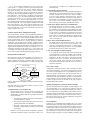
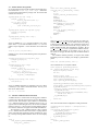
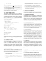
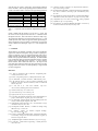
Fast Integration of EDA Tools and Scripting Languages
Dept. of EECS, U. C. Berkeley
Berkeley, CA 94720, USA
[email protected], [email protected]
Abstract
EDA tools are implemented to automate a design task efficiently,
but they often lack flexibility to be highly customizable or programmable. Some EDA tools have a primitive and unique command language to realize programmability, but usually it further
complicates a design flow. We thus propose methods and techniques to fast link EDA tools with a popular scripting language
such as Perl[1], Python[2] or Tcl[3] for ease-of-use and better integration. This approach encourages rapid prototyping of algorithms,
code reuse, customizability, extensibility, interoperability between
tools, and easier testing of application program interface(API)’s.
Based on the proposed methods and techniques, we efficiently
built several Perl/Tcl/Python interfaces to EDA packages such as
LEF/DEF parser, Synopsys .lib parser, Verilog PLI2.0 routines,
SDF reader/writer and so on.
1 Introduction
Scripting plays an important role in the current chip design methodology. Conventionally, it has been used to automate a design flow,
integrate a variety of tools, patch a buggy tool, extract required
information, modify an output foramt, and prepare a configuration
file. Moreover, scripting languages are also used extensively within
some EDA tools to provide a basic programming capability such as
defining a variable, defining an option value, executing a command
sequence, recording a command sequence, switching on/off a tool’s
feature, capturing output results, branching and looping. It is thus
important how to fast integrate a scripting language into the existing EDA code.
gramming task have been handled automatically in the language
itself so that a user can write less code to do the same job. Scripting languages are typically characterized as interpreted, typeless
programming language, high productivity and short development
time with less favorable performance[9, 10] compared with system
programming languages such C or C++. For the same functionality, a factor of at least 4X more development time is reported for
programming in C/C++ compared with scripting language such as
Perl, Python or Tcl[10, 9]. This factor is observed as high as 60X
for a special database application[10]. Also, the length of a program in a scripting language can be much shorter than that in a
system programming language, which implies scripting programs
could be easier to revision or maintain. However, for a performance
oriented task, scripting languages are not most efficient or optimal compared with system programming languages such as C or
C++[9]. This area is where a traditional programming language
can work very well. We observed a factor 20X to 50X speed-up
for the performance of an optimized C or C++ program over that
of the same functionality of a Perl program. In summary, scripting
languages trade off execution speed to reduce development time.
Ideal EDA Tool Architecture
A mixed language approach can combine a scripting language at
the top and uses the dedicated and optimized algorithm engines
from system programming languages such as C/C++ for the underlying structures. The system configuration may be as shown
in Fig.1, where a scripting language is used to integrate or ”glue”
GUI
The Need for a Popular Scripting Language
EDA tools are typically characterized as a highly efficient computation engine to optimize a design or do design analysis. However,
they lack flexibility to be highly programmable to satisfy users’
needs. Some tools have a limited or very primitive scripting language such as Sis[4] or Vis[5], but they are neither extensible nor
flexible and uneasy to program, and don’t have a full programming
capability which is important for automating a realistic design job.
Commercial tools typically adopt a dialect of a popular language
such as Skill for Silicon Ensemble[6], Scheme for Apollo II[7], or
Tcl[3] for Design Compiler[8]. However, a specific programming
language may be another stopping factor for a user to further explore the tool, just because a long learning curve is required for a
new programming language. For modern chip design, a designer
has to deal with at least a dozen of tools, each of which may have a
unique command language plus several specific input formats. This
could be a very error-prone process and impede design productivity
seriously.
Pros and Cons of Scripting Languages
Scripting languages are well-known to be ideal for a higher level
programming job and system integration. Most detail of a pro-
Interactive Use or Scripts
Interface
Wrapper
Scripting Language(e.g. Perl or Tcl)
Interface
Wrapper
Interface
Wrapper
Interface
Wrapper
EDA Engine
Database
Numerical
Modeling
Figure 1: Tool Integration by a Scripting Language
tools together. This architecture partition of a software application
system follows the guidelines in [10] such that the system programming languages are used in speed critical tasks, implementing complex algorithms and data structures, being well-defined and changing slowly, while the scripting language is used to connect existing components, build a graphical user interface(GUI), maintain
consistency work or routine jobs, and adapt to rapid evolving endusers’ applications. This approach is very flexible, extensible, and
easy for scripting and rapid prototyping of an application system or
building a design flow.
In [11, 12], the authors implemented a tool, vex, which integrates several C++ packages to achieve non-trivial design tasks
such as design browsing, tri-state checker, module partitioning,
FSM graph browsing, alias removal and a netlist connection
database. It also interfeces with Tk[3], a graphical user interface,
and a binary decision diagram(BDD) package[13] for more complex applications. This represents a paradigm of the ideal EDA
tool architecture. In [13], the authors implemented a BDD package with a Perl interface, PerlDD, which also enables a graphical
BDD calculator, DDcal. Based on the Perl platform, DDcal combines a BDD package and a GUI package(Tk) to display BDD data
structures graphically. This shows another example for the ideal
EDA tool architecture. Also, many commercial EDA tools seem
to have adopted this architecture internally, but they are either limited to one single tool or a very close environment which is hard to
integrate with the other tools.
Useful for Software Reuse and Rapid Prototyping
This tool architecture provides a full programming capability to
end-users and a platform for dynamically loading modules, which
can selectively load or replace software modules without affecting the system integrity. Also, it can immediately leverage the existing modules or packages of a scripting language to extend its
functionality such as graphical user interface, a database engine,
numerical computation algorithms, networking modules and so on.
Therefore, rapid prototyping and software reuse can be much easier
without tedious compilation or linking in a traditional C/C++ development environment. If the original C/C++ source codes were
not available, this could be especially useful since the APIs of each
tool are still accessible from the scripting language’s interface.
Interoperability Consideration
EDA tools have been lack of interoperability for a long time. Several methods are available for communicating between two programs or working processes[14]. Consider a delay calculator and a
Verilog simulator as an example(Fig.2). The delay calculator will
Script Language
API
API
PLI
2. Programming Language Interface
The second approach uses a set of programming language interface(PLI)’s to communicate between tools. For example,
the delay calculator will provide service routines, linked to
a host, the Verilog simulator, through these PLIs. One has
to be very careful about data types and the usage details of
PLIs to make it work smoothly. It requires a separate linking
pass to make it an executable simulator, resulting in a very
time-consuming, non-extensible, and inflexible solution.
3. Client-Server Mode or Interprocess Communication
The third approach uses a client-server mode. For example, the delay calculator runs as a server waiting for the Verilog simulator to input information and feedbacks with delay
data. It can work as a distributed computation manner. However, this requires a validated set of communication protocol
to make this possible. The development time can be much
longer before it is reliable and efficient for realistic design
tasks. Also, the network traffic may further impede the efficiency of this approach.
4. Direct Access of Internal Data Structure
The fourth approach uses internal data access. This is the
most efficient one. However, due to data abstraction, code
consistency, and different tool providers, it is almost against
all the software engineering principles. It is not only difficult
to maintain, but also easy to crash a whole system.
5. API Access through a Scripting Language
As we proposed, all the design tasks can be integrated into
a uniform platform to reduce the text/binary file exchange,
and end-users can access the APIs of EDA tools to do customization to fit their needs using a most popular scripting
language such as Perl, Tcl or Python. The development time
can be much reduced. Each component can be hooked up
to that platform dynamically under the control of a script to
complete a design task.
Ease of APIs’ Testing
SDF
Delay Calculator
script. However, it results in a very complicated and unreliable design flow.
Verilog Simulator
Internal
data structure
Server−Client
mode
Figure 2: Delay Data Exchange between Delay Calculator and Verilog Simulator
send delay data back to the Verilog simulator. There are several
approaches to exchanging data:
1. Specific Format by Text or Binary File
The first approach uses a specific format to exchange data
through normal OS files, for example, using standard delay
format(SDF) to exchange delay data. This approach has three
serious drawbacks:
1. Extra dumping of data into the specific format and parsing of that format are required,
2. The input and output formats between two tools can be
possibly mismatched or incompatible,
3. The input or output formats are thus fixed without any
flexibility to change unless any further post processing
is performed.
In practice, one may fix the format incompatibility problems
with ad-hoc methods by using a script such as a Perl or Tcl
Comprehensive testing of software’s APIs is generally very difficult and time-consuming. The common testing approach is based
on an outer input and output pair. It can not handle finer grain testing for any specific API. However, with the integrated APIs in a
scripting language, a tool developer can design a set of very dedicated scripts to test each API and does not have to compile another
testing programs to intervene with the production code. Therefore,
a variety of regression tests for the API can be easily created to
guarantee high quality software.
Speeding up Integration by Using an Interface Wrapper
Typically, integrating APIs into a popular scripting language is not
very straightforward. A lot of extra work is required to make the
interface self-consistent. We emphasize minimal extra coding to
link a set of APIs into a scripting language, and provide several approaches to easing the integration work. SWIG[15] is designed to
automatically generate the wrapper or interface routines. It can reduce most of routine jobs into a simple configuration and generate
the required code to bridge the gap.
Our Contribution
In this paper, as a complement and extended work to [14], we first
discuss and address techniques using simplified wrapper and interface generator (SWIG)[15] to link the features or functions which
an EDA tool may have to a most popular script language such Perl,
Tcl or Python. Perl and Tcl have been extensively used in the design community for a long time due to their powerful string pattern
match by regular expressions, scripting capability, popularity, and
extensibility. Both can process a simple text file very efficiently using regular expressions without the tedium to program a full parser
and a lexical analyzer. We then provide interface building techniques which SWIG does not support but exist in almost EDA tools.
Finally, we will examine several interface packages we have implemented efficiently based on these techniques.
Organization of this Paper
After compilation and linking[15, 19], SWIG will create a constructor function new point which wraps the constructor of class
point, and several member functions in Perl/Tcl/Python with a prefix point such as point print. Moreover, the data field access
functions are also generated, for example, a read function for field
x as point x get, and a write function for field x as point x set.
A Perl script can be used to create a point and manipulate the data
fields as the following:
We will first introduce the SWIG functionality briefly. It is followed by a variety of techniques useful for linking common EDA
tool’s functions in Section 3. In Section 4, we will discuss an interface creation flow. Section 5 deals with interface design consideration. In Section 6, we will examine several application systems
which implement our approach and show comparison between different approaches.
use point;
package point;
$a = new_point(3,2);
print "X=",point_x_get($a),"\n";
point_y_set($a,8);
print "Y=",point_y_get($a),"\n";
2 Review of an Interface Generator
load ./point.so;
set a [new_point 3 2]
puts "X=[point_x_get $a]"
point_y_set $a 8
puts "Y=[point_y_get $a]
An interface generator[15, 16, 17, 18] is used to generate the necessary wrapper functions for a C/C++ program to interface with a
scripting language. It can translate or map data types between languages to fit the interface needs. Typically, a scripting language
must have several specific steps for calling a C/C++ function including:
1. Globally initialize a C/C++ module,
2. Register the functions’ name in the target scripting language,
3. Map the scripting language’s typeless argument data into
typed ones for the C/C++ function,
4. Check the arguments for the correct number and type,
5. Call the C/C++ function,
6. Translate the output typed data into the scripting language’s
typeless data and place them onto the argument return stack,
7. Release extra memory space allocated during the steps above.
Therefore, an interface generator should be able to generate wrapper codes to automatically handle most of the above correctly, and
supplies methods to map or translate data between a scripting language and a system programming language. It can be regarded as
a template-driven code generation technique[16], which is used extensively in computer aided software engineering(CASE). SWIG
is a tool used to generate wrapper codes automatically for C/C++
codes to interface with scripting languages such as Perl, Tcl,
Python, Guile, and etc. Moreover, it can also generate data structure access subroutines to read or write a C/C++ structure, variable
or object.
2.1 Simple Example
The following is a simple example to show how to use SWIG to
easily generate an interface. Consider a simple C++ point class:
class point{
public:
int x,y;
point(int xin,int yin):x(xin),y(yin){}
void print(){
cout << "(" << x << "," << y << ")";
}
};
We can create an interface file in SWIG as:
%module point
%{
#include "point.h"
%}
%include "point.h"
In Tcl, one can use the following script:
SWIG also supports object-oriented interfaces. With an additional SWIG switch(-shadow for Perl), one can use a Perl script:
use point;
package point;
$a = new point(3,2);
print "X=$a->{x}\n";
$a->{y}=8;
print "Y=$a->{y}\n";
In Tcl, it becomes:
load ./point.so;
point a 3 2
puts "X=[a cget -x]"
a configure -y 8
puts "Y=[a cget -y]"
In Python, one can use:
from point import *
a=point(3,2)
print "X=",a.x
a.y=8
print "Y=",a.y
Note that for a simple C++ class, one may not even have to
change the interface configuration file for a different target scripting language. SWIG uses a technique called typemap functions
which are the customizable transformaion code that translate interface data types between scripting languages and C/C++ functions.
3 Useful Techniques
In the following sections, we will discuss techniques used to fast
link EDA tools with scripting languages[14]. Most of SWIG techniques have been shown in [15, 19]. However, some of critical
techniques that an EDA tool needs are still not supported in SWIG.
The detail of these techniques are also provided in our web site
[20].
3.1 Reuse of an Existing Command Dispatcher
Many EDA tools have their own command dispatcher for their original scripting language. It is possible to leverage this mechanism to
transparently import their original command set into a target scripting language[14]. In the initialization code, the original command
should be registered one by one into the target scripting language’s
command table. A Tcl and a Perl interface for Sis[4] have been
built in this way[20]. It is surprising that the original Sis scripts
can be executed without any modification using this approach[14].
3.2 Variable Number of Arguments
It is not uncommon an EDA tool has a higher level API with a function interface like foo(int argc, char **argv). SWIG does
not support this kind of function prototype well. The work-around
solution can be shown as:
%typemap(perl5,in) char **argv {
$target = (char **)
malloc(n_arg*sizeof(char *));
for (;n_arg;--n_arg) {
$target[n_arg-1]=
(char *)SvPV(ST(n_arg-1),PL_na);
}
}
%typemap(perl5,ignore) int argc(int n_arg){
$target=n_arg=items;
items=1;
}
%typemap(perl5,freearg) char **argv {
free($source);
}
where we skillfully use ignore typemap in SWIG to carry information about argc and relax the SWIG check(items=1) for the
number of input arguments. A Perl subroutine call can thus look
like:
foo("-i",5,"-f","-x","bar.dat");
Similarly, for Tcl, one can use the following code to wrap this function interface:
%typemap(tcl8,ignore) int argc(int n_arg){
$target=n_arg=objc-1;
objc=2;
}
%typemap(tcl8,in) char **argv{
int templength,i;
$target = (char **)
malloc(n_arg*sizeof(char *));
for (i=0; i < n_arg; i++) {
$target[i]=Tcl_GetStringFromObj(
objv[i+1], &templength);
}
}
%typemap(tcl8,freearg) char **argv {
free($source);
}
%}
static char *Perl_callback_fn=NULL;
void node_alloc_C_daemon(node_t *node){
dSP ;
SV *sv;
if(Perl_callback_fn==NULL)return;
ENTER ;
SAVETMPS;
PUSHMARK(SP) ;
sv=sv_newmortal();
SWIG_MakePtr(sv,(void *)node,
SWIGTYPE_p_network_t);
XPUSHs(sv);
PUTBACK ;
perl_call_pv(Perl_callback_fn,
G_DISCARD);
FREETMPS ;
LEAVE ;
}
%}
where SWIG MakePtr is used to encode a pointer into a Perl representation, and perl call pv is a Perl built-in function for calling
a function with a string argument. The capital letter words above
are pre-defined macros in the Perl internal core[16], and they are
actually handling the Perl stack and temporary variables. We use
Perl callback fn to record a registered Perl callback function.
More sophisticated examples can be found in [19, 16, 20]. For
Tcl version, it can apply the same steps with Tcl built-in function
calls[14].
For automatic callback generation, we improve this manual
translation process into a tool[20]. For example, a global function
pointer
static int (*FooPtr)(double, char *);
can be translated into a C-to-Python callback
static PyObject* PyCallBack_FooPtr=0;
int _cbwrap_FooPtr(double f,char *msg){
PyObject *arglist,*result;
int ret ;
PyObject *arg0, *arg1;
if(!PyCallBack_FooPtr)return ret;
arg0 = PyFloat_FromDouble(f);
arg1 = PyString_FromString(msg);
arglist=Py_BuildValue("(OO)",arg0,arg1);
result=PyEval_CallObject(PyCallBack_FooPtr,arglist);
Py_DECREF(arglist);
{ PyObject *args=Py_BuildValue("(O)",result);
Py_XDECREF(result);
if(!PyArg_ParseTuple(args,"i:CALLBACK",&ret))
return (int) NULL;
Py_XDECREF(args);
}
return ret;
where we skillfully manipulate the arguments in the Tcl’s calling
convention[3, 15] to achieve our desired interface. The Tcl procedure call can thus look like:
foo -i 5 -f -x bar.dat
3.3 Automatic Callback Function Generation
A callback function is a function that will be triggered or called for
a special event. When the special event occurs, the callback function is executed. This technique is quite common in a customizable
C/C++ application library such as LEF/DEF parsers in [21]. In
opposite of the normal calling direction, the execution of callback
function is from C/C++ code to invoke a scripting language subroutine. However, SWIG has no support for this kind of mechanisms.
The technique to create a callback function is first to register
a C/C++ callback function which will execute a scripting function
with its input and output arguments properly translated. For example, a node processing callback function in Sis can be shown[20]
as:
%init %{
node_register_daemon(DAEMON_ALLOC,
node_alloc_C_daemon);
}
Also, the associated interface configuration will be generated as:
%typemap(python,in) PyObject *{ $target=$source;}
%inline %{
void register_FooPtr(PyObject *pyfunc){
if(PyCallBack_FooPtr)
Py_DECREF(PyCallBack_FooPtr);
PyCallBack_FooPtr=pyfunc;
Py_INCREF(pyfunc);
}
%init %{
FooPtr=_cbwrap_FooPtr;
%}
register FooPtr is thus used in Python to register a callback fuction pointed by FooPtr. That is to say, this tool will generate the
necessary callback interface for a user to use a Python callback
without writing any interface code.
3.4 Output Capture and Redirection
Rich regular expression operations in Perl and Tcl can be used to
extract run-time output information of an API. The idea is similar to
UNIX’s output redirection. A monitored API can be executed with
its standard output and standard error output redirected to variables,
respectively. A post-processing by string pattern matching using
regular expression can extract useful information. This approach is
very straightforward and flexible in analyzing output results. It can
be used when nothing is disclosed about the internal data structures
of an API. The redirection method can be found in [14, 16]. The
drawback is its inefficiency due to the print-out of redundant data.
This approach is not uncommon in commercial EDA tools such
as Design Compiler[8]. Also, it is perfect for a black-box testing of
an API. One does not have to understand any internal operations of
an API to test it.
3.5 Structure Marshaling Code Generation
SWIG does not support translation of a C’s struct into a scripting
language’s element. However, it may be required for some simple
data structures. For example, a simple data structure
strucrt coord{
float x,y;
};
can translated into a list in Perl easily. We write a tool supporting
this translation via typemap functions in SWIG[20]. One can thus
use this tool to generate the necessary typemaps in SWIG without
writing any interface codes.
3.6 C++ STL Handling
Standard template library(STL) is a very flexible, popular and
handy library for basic data structure templates in C++. Among
the templates in STL, vector class is especially useful for building a list efficiently. It is naturally translated into a list of objects in
a target scripting language, for example, a typemap in SWIG:
%typemap(perl5,out) vector<Cell *> *{
if($source){
if($source->size()>items)
EXTEND(sp,$source->size()-items);
for(vector<Cell *>::iterator i=$source->begin();
i!=$source->end();i++){
ST(argvi) = sv_newmortal();
SWIG_MakePtr(ST(argvi++), (void *)(*i),
SWIGTYPE_p_Cell);
}
}
}
where $source is the return value of a C++ function, EXTEND()
is a Perl macro to extend the return stack space, ST() is a macro
for the Perl stack element, and SWIG MakePtr is used to translate a
C++ representation of pointer into the Perl representation. One can
thus use:
@cell_list=all_cells();
foreach $cell(@cell_list){
print $cell->name(),"\n";
}
to access each cell in a cell list. For Tcl and Python, it can be done
similarly[20].
3.7 Interface for Data Structure Traversal
It is common that some data structures need to be examined one by
one, for example, in Sis[4], foreach node is defined as a macro
used to traverse each node in a network. Similar to the STL’s
iterator implementation, it can be very efficiently implemented
without building another list of nodes. The Tcl implementation
of foreach node command is very similar to the Tcl command
while implementation[3].
%native(foreach_node) int _foreach_node();
%{
static int _foreach_node(
ClientData clientData,
Tcl_Interp *interp,
int argc, char *argv[]) {
node_t* _arg3 = NULL;
network_t * _arg1 = NULL;
lsGen gen;
int code;
if (SWIG_GetPtr(argv[2],(void **)&_arg1,
"_network_t_p"))
return TCL_ERROR;
foreach_node(_arg1,gen,_arg3){
char result[256];
Tcl_ResetResult(interp);
SWIG_MakePtr(result, (void *)_arg3,
"_node_t_p");
Tcl_SetVar(interp,argv[1],result,0);
code=Tcl_Eval(interp,argv[3]);
if(code == TCL_CONTINUE)
continue;
else if(code == TCL_BREAK)
return TCL_OK;
else if(code != TCL_OK)
return code;
}
return TCL_OK;
}
%}
Therefore, one can use
foreach_node x $network {
puts "Node [node_name $x]"
}
to dump all the name of the nodes in $network. For Perl, unfortunately, it can not have this kind of syntax sugar, but we can mimic
the syntax as
while($x=each_node $network){
print node_name($x),"\n"; }
or
for(;$x=each_node($network);){
print(node_name($x),"\n"); }
The implementation of each node can be:
%inline %{
node *each_node(network_t *n){
static network_t *network=NULL;
static lsGen gen;
node_t* node;
if(network!=n){
network=n;
foreach_node(network,gen,node){
return node;
next_node:
}
network=NULL;
return NULL;
}else
goto next_node;
}
%}
Note that we skillfully make each node return one node each time
it is called by using static variable techniques. Only one traversal is valid for the whole program due to its single anchor(static
lsGen gen) to point to the next node.
Alternatively, one may use the approach in the previous section
using STL to build another vector or list to collect the pointers with
the cost of extra memory allocation and release.
3.8 Automatic Makefile Generation
The compilation and linking environment can be very tedious before the first interface code is built and working. Perl has a module
ExtUtils::MakeMaker used to automatically write Makefile that
will compile and link the necessary headers and libraries to create
a dynamically shared module. Consider an interface configuration
file Graph.i and a C++ file Graph.cpp. We can use the following
Perl code(Makefile.PL) to generate the Makefile:
use ExtUtils::MakeMaker;
$module=’Graph’;
WriteMakefile(
’NAME’ => $module,
’OBJECT’=>"${module}_wrap.o ${module}.o",
’LDDLFLAGS’ => ’-shared’,
’CC’ => ’g++’, ’LD’ => ’g++’
);
sub MY::postamble {
return << ’END’;
SWIG
= swig
SWIGFLAGS= -c++ -perl5 -shadow
$(NAME)_wrap.c :: $(NAME).i $(NAME).h
$(SWIG) $(SWIGFLAGS) $(NAME).i
END
}
The specific steps include:
perl Makefile.PL
make
make install
We also provide a script used to automate the Makefile generation
based on the SWIG module[20]. It currently supports Perl, Python
and Tcl.
4. Write a test script in the target scripting language to check for
the expected API’s behavior,
5. Fine tune the interface for consistency and ease-of-use,
6. Create a template to generate the interface for the rest of APIs,
7. Install this interface library into the central repository of the
target scripting language’s library.
5 Interface Design Consideration
Naive translation of header files can result in an unusable interface.
It is thus required some attention to design an ease-of-use interface.
5.1 Implementation Independency
A good interface can be served as isolation or information hiding
for implementation from the external applications. The revision of
implementation can be thus independent of the external applications. Therefore, a better interface should involve fewer internal
structures. Using C/C++ macro definitions and SWIG supported
mechanisms, such as ”ignore” typemap function, and default argument values, can be helpful to reduce complexity of an interface.
5.2 Consistency and Ease-of-Use
An interface should be designed with consistency, including a naming convention, an argument passing convention, a function calling
convention, memory allocation/release, object handling, list data
structure representation, and even the documentation style, etc.
Sometimes, it may require extra helper functions or macro definitions to make the interface consistent. SWIG supports %name,
%rename and typemap mechanisms to refine an interface.
5.3 Selective API Export
Blindly exporting all APIs of an EDA tool can result in a huge and
inefficient interface library. The target application domain has to
be taken into consideration when designing an scripting language
interface. SWIG supports a switch macro(i.e. #ifdef SWIG) to
selectively export API fuctions for interface code generation.
It is also possible to partition an interface of EDA tools into
several dynamical loadable modules, each of which is grouped according to similar functionality or object classes. An application
can load the necessary modules to complete its task. Perl supports
AUTOLOAD[1, 16] mechanism and package reference to selectively
load modules. Python and Tcl support a similar mechanism as well.
3.9 Miscellaneous Techniques
We are aslo building a library to collect the interface handling techniques in [20], for example, how to handle an array of pointers, how
to make void* compatible with other data types, how to wrap a
C++ function which has multiple interfaces, how to write typemaps
for C++ references and so on. With these techniques, a scripting language can be used more smoothly at higher level without
much detail of its original C/C++ APIs, for example, using lists and
hashes extensively to manipulate objects in Perl, Tcl or Python.
5.4 Completeness
Completeness is the most important factor to decide if one interface
library is usable for a specific application. Typically, applications
are favorable to be written in one scripting language with library
support either from script modules or C/C++ libraries. Therefore,
the interface has to provide all the features or functions an application needs. In practice, we have to iterate the interface design and
test through typical domain-specific applications to make it complete.
4 Interface Creation Flow
6 Case Study
With the help of interface generator, interface building can be very
efficient and much easier than hand-craft. SWIG[22] reports a first
time user used 10 minutes to wrap OpenGL, a 3D graphics library.
In general, we observe an iterative building flow as:
1. Start with the header files of C/C++ library, and create an
initial configuration file,
2. Edit a Makefile template to generate a project’s Makefile,
3. Test compilation and linking, and remove parsing difficulties
for SWIG,
We implemented several interface packages in [20] to experiment
with our idea.
6.1 Perl/Python/Tcl interfaces to LEF/DEF Parsers
Conventionally, the LEF/DEF files are parsed by assuming certain
format rules in addition to its syntax. Perl is often used to extract
information in this context using string pattern matching by regular expressions. Due to the format assumption, one can use a Perl
script to do simple parsing and obtain design information in very
short time. However, the script is hardly reusable, and this approach is clearly slow and unreliable.
Using SWIG plus the techniques in Section 3, we implemented
Perl/Python/Tcl interfaces to LEF/DEF parsers from [21]. These
parsers are released from the originator. Therefore, it is complete
and formal without any parsing glitches. With the scripting language interface, one can easily extract required information using
higher level programming constructs such as list, hash and string.
For example, pin names can be extracted from a LEF file using a
Python script:
from LEF import *
def pinf(t,pin,ud):
if t==lefrPinCbkType:
print "This is a lefrSetPinCbkType",
print "Pin=",pin.name()
return 0
lefrSetPinCbk(pinf)
lefrRead("complete.5.2.lef")
where lefrSetPinCbk registers a Python callback function pinf.
When the parser top level routine lefrRead is invoked and a pin
statement is parsed, pinf will be called or triggered to process the
pin object.
DEF and LEF parsers have actually very similar structure in
source code style. It was thus very easy to implement one interface package after the other since only the name replacement was
involved.
6.2 Perl/Python/Tcl interface to Synopsys .lib Parser
Similarly, we implemented an interface package for Synopsys .lib
parser, which is released from Synopsys TAP-in program[8]. Synopsys .lib format is an ASIC library format used extensively in
Synopsys’ tools. The ability to interface with the parsers enables
the possibility to efficiently and correctly extract a variety of information from a cell library, such as timing information, logic function of a cell, power consumption information and so on. This is
crucial in developing ASIC design tools, and important for checking or ensuring the quality of a cell library.
Using this package, for example, we can extract the area of a
cell in Tcl as:
load "./si2dr.so" si2dr
PISetDebugMode
ReadLibertyFile "sample.lib"
proc cellArea {libName cellName} {
set lib [PIFindGroupByName $libName library]
set cell [GroupFindGroupByName $lib $cellName cell]
return [SimpleAttrGetFloat64Value \
[GroupFindAttrByName $cell area]]
}
puts "AND2 area=[cellArea std018 AND2]"
This approach helps CAD developers to rapid prototype an application system and reduce the tedium to code a complete parser each
time, but still have a complete and fast low level parser routine
available.
my ($A,$B,$W)=@_;
printf " A=0x%02X B=0x%02X\n",
$A->{value},$B->{value};
assign($W,$A->{value}*$B->{value});
}
sub py_mult{
my ($CK,$A,$B,$W)=@_;
always(posedge($CK),\&mult_ab,[$A,$B,$W]);
}
or in Python as:
from vlog import *
from my_model import *
def mult_ab(A,B,W):
print "
A=0x%X B=0x%X" % (A,B)
assign(W,A.value*B.value)
def py_mult(CK,A,B,W):
always(posedge(CK),mult_ab,(A,B,W))
Compared with a C hardware model using PLIs, the detail is much
reduced, and chip designers can thus focus how to model a system
behavior in the first place.
Also, this approach enables a Verilog simulator to execute
Perl/Python/Tcl codes during its simulation using Verilog system
tasks. It is thus easier for users to explore in-depth information
about a netlist or simulation using this approach.
6.4 An SDF Reader and Writer
We will examine a SDF reader and writer package(included in
Perl/Tcl Interface for Gate-level Netlist Engine[20])
in this section.
Due to incompatible SDF formats between EDA tools, we
experienced many difficulties in annotating delay information
smoothly back to Verilog simulators or static timing analyzers from
a P&R tool. The traditional ad-hoc approach uses Perl scripts to fix
the problems when a tool complains about syntax problem or timing record mismatch. We implemented a C++ parser for SDF files
and a delay value database to fix the format incompatible problem.
Using the proposed approach, we employ Perl or Tcl as the top
level controling scripts to program the whole application tool. The
application system architecture is shown in Fig. 3. It enables us
Application Scripts
Perl or Tcl
Interface
Delay
Database
Reader/Parser
6.3 Perl/Python/Tcl interface to Verilog PLI2.0 interface
We also implemented a Perl/Python/Tcl interface to Verilog PLI2.0
using our callback generation tool. Although this approach has no
benefit over speed, it still serves as a very good starting point to prototype a PLI application. For example, we can model a hardware
module, a synchronous multiplier, in Perl as:
use vlog;
package vlog;
require "my_model.pl";
sub mult_ab{
Results
SDF File
Figure 3: SDF Reader/Writer Application System
to do any checking, statistics or queries based on the C++ delay
database engine, for example, checking if some nets or cells are
under-driven or over-driven, giving statistics about a specific cell’s
delay, derating a specific cell’s timing, computing timing skews,
checking hold time problem or comparing two SDF files to identify the largest timing difference.
C++ STL has been used extensively in this SDF parser engine
to build a delay database. Some helper functions are built to output
a list structure in the Perl or Tcl interface. For comparison, we build
a pure C++ version and a pure Perl version SDF reader and writer
with the same set of YACC syntax rules. We found the following
metrics in Table 1, where our proposed approach is marked as ”Proposed” in the third column. Note that in the proposed approach the
Run time
Memory Usage(bytes)
Code Length
Interactive Use
Ease for Revision
Re-Compilation for
different applications
Pure C++
3.25secs
6.7M
819 lines
No
No
Proposed
20.09secs
7.4M
155 lines
Yes
Yes
Pure Perl
85.72secs
10.0M
232 lines
Yes
Yes
Yes
No
No
Table 1: Comparison between different implementation architectures
reader is called from the interface to access the C++ parser, and
the writer is a Perl script which accesses the C++ database’s APIs
through the interface. This result seems to follow the study of [9].
The performance difference can be 26X between the pure C++ code
and the pure Perl code, while our approach exhibits graceful degradation with minor increase in memory consumption. Our approach
clearly combines the advantages of pure C++ code and pure Perl
code.
7 Conclusion
We introduced a very flexible, extensible, ease-of-use, and efficient
approach for EDA tool integration using a modern scripting language as a platform. Also, we suggested techniques and tools for
linking smoothly and efficiently with a popular scripting language.
Based on the proposed methods and techniques, we demonstrated
how we efficiently built several Perl/Tcl/Python interfaces to EDA
packages such as LEF/DEF parser, Synopsys .lib parser, Verilog
PLI2.0 routines, SDF reader/writer and so on. We expect in the
near future more and more EDA tools will provide these scripting
language interfaces for better tool interoperability, or support APIs
for easier integration.
References
[1] L. Wall, T. Christiansen, and R. Schwartz, “Programming Perl”.
O’Reilly and Associates, 1996.
[2] M. Lutz, “Programming Python”, O’Reilly and Associates, 1996.
[3] J. K. Ousterhout, “Tcl and the Tk Toolkit”, Addison-Wesley, 1994.
[4] E. M. Sentovich and et al, “SIS: A System for Sequential Circuit
Synthesis”, Electronics Research Laboratory Memo. No. ERL/UCB
M92/41, May 1992.
[5] A. Aziz and et al, “VIS User’s Manual”,
cad.eecs.berkeley.edu/Respep/Research/vis/index.html.
http://www-
[6] Cadence web site, http://www.cadence.com.
[7] Avant! web site, http://www.avanticorp.com.
[8] Synopsys web site, http://www.synopsys.com.
[9] L. Prechelt, “An Empirical Comparison of Seven Programming Languages”, IEEE Computer magazine, pages 23–29, Oct. 2000.
[10] J. K. Ousterhout, “Scripting: Higher Level Programming for the 21st
Century”, IEEE Computer magazine, Mar. 1998.
[11] J.P. Bergmann and M.A. Horowitz, “Vex - A CAD Toolbox”, Design
Automation Conference, Jun. 1999.
[12] J.P. Bergmann and M.A. Horowitz, “A toolkit for creating verilog
HDL tools”, http://vextools.com.
[13] F. Somenzi, “CUDD: CU
http://vlsi.colorado.edu/fabio.
Decision
Diagram
Package”,
[14] P. Chen, D. A. Kirkpatrick, and K. Keutzer, “Scripting for EDA Tools:
A Case Study”, To appear in International Symposium on Quality of
Electronic Design, Mar. 2001.
[15] “Simplified Wrapper and Interface Generator”, http://www.swig.org.
[16] S. Srinivasan, “Advanced Perl Programming”, O’Reilly and Associates, Mar. 1997.
[17] “Scripting Interface Languages for Object-Oriented Numerics”,
http://www.acl.lanl.gov/siloon/.
[18] W. Heidrich and P. Slusallek, “Automatic Generation of Tcl Bindings
for C and C++ Libraries”, Proceedings of the Tcl/Tk Workshop 1995,
Jul. 1995.
[19] D. M. Beazley, D. Fletcher, and D. Dumont, “Perl Extension Building
with SWIG”, O’Reilly Perl Conference 2.0, pages 17–20, Aug. 1998.
[20] “ScriptEDA”, http://www-cad.eecs.berkeley.edu/pinhong/scriptEDA.
[21] “OpenEDA”, http://www.openeda.org.
[22] D. M. Beazley, “Tcl Extension Building With SWIG”. In Tutorial of
6th Annual USENIX Tcl/Tk Conference, Sep. 1998.