1
READ AND SAVE THESE INSTRUCTIONS
PART #469690
DDC CONTROLLER
for ENERGY RECOVERY
®
Installation, Operation and Maintenance Manual
MANEUVERING THROUGH THE CONTROLLER
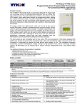
The DDC controller is located in the control panel on the energy recovery unit.
The face of the DDC controller has six buttons allowing the user to perform
various tasks such as viewing conditions or changing set points. A brief
description of the six buttons is provided. For additional details, refer to the
page references included.
Prior to accessing the controller, confirm the functions that were provided with
the unit by referencing the DDC Code shown
on the controller Start-Up screen.
Greenheck Fan Corp.
ER DDC v3.##
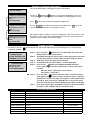
The Start-Up screen appears when power is applied to the controller. The program version
and code are shown on this screen. The code shows the user what components and
functionality were provided with the unit and also dicates how the program operates. Below
is a description of the code.
Code: GY2X000B
Name
Heat
Cool
HGRH
Frost
Economizer
UnOccupied
Mode
Communications
G
Y
2
X
0
0
0
B
GFC
G None – Disable
Enable
GFC
Enable
Alarm
X None – Disable X None – Disable X None – Disable
Y CW
0 None – Disable
0 None – Unit Off
0 None
X
C On/Off
A Timed Off
1 On/Off
1 Cycle on Room
1 Modbus
M
PDx 1 stg
1 Mod
B Preheat
2 Modulating
2
LON
L
PDx 2 stg
2
BACNet
B
PDx 2 stg
Modulating
None – Disable
3
None – Disable
None – Disable
None – Unit Off
BACNet
Description
Reference
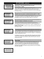
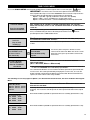
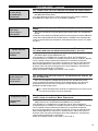
Indicates both visually on the controller (the button lights up) and to the Building
Management Systems (BMS) (field-wired) that something is not functioning normally.
Page 3
The arrow keys allow the user to scroll through different screens and adjust
parameters.
Page 3
A. In screens with adjustable parameters, pressing the Enter key moves the cursor
from the upper left corner of the screen to the parameter. The arrow keys can
then be used to adjust the parameter.
B. To move to the next parameter on the same screen, press the Enter button.
C. To save the change, press the Enter button until the cursor moves back to the
upper left corner of the screen.
Page 3
Up Arrow
Down Arrow
Enter
Escape
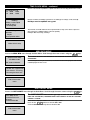
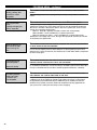
Allows the user access to the Main Menu. The following adjustments can be made:
• Unit Status
• Set Points
• Manual Overrides
• Analog & Digital Input/Output Setup
Program
Allows the user access to the Program Menu
• Time Clock Setup
• Miscellaneous Information
• Unit On/Off
Page 4
Page 17
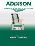
NOTE: If this controller needs to be interfaced with a BMS (ie: Lonworks, BACnet or Modbus), please refer to page 23 for an integration points list.
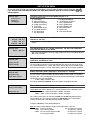
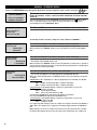
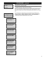
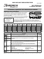
DDC Controller for Energy Recovery
24 VAC to Controller
Outdoor Air Intake Temperature Sensor
Cold-Coil Temperature Sensor
Sensor B1, B2, B3 Commons
Room Temperature Sensor
or Digital Call for Cool
Analog Sensor Inputs
Supply Discharge Temperature Sensor
Humidistat
24 VAC When Unit On
Frost Control Enable
Analog Cooling Output (CW)
Hot Gas Reheat Analog Output
Supply Fan Proving
Wheel Pressure
Unit On/Off
Exhaust Fan Proving
Occupied/Unoccupied Input
Dirty Filter
Compressor Limit
Digital Inputs
Wheel Rotation Alarm
Output to Exhaust Fan
24 VAC from Supply Fan Proving
Digital Outputs
Analog Output to Energy Wheel
Analog Heating Output (HW or Electric)
Analog Outputs
24 VAC for Analog Outputs
Output to Supply Fan
Heating Enable (IG or Electric)
1st Call For Cooling
2nd Call For Cooling
24 VAC
Output to Dampers
Alarm
Dry Contact
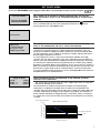
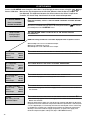
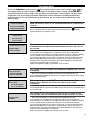
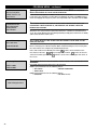
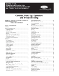
Example of parameter adjustment
The cursor always begins in the upper left corner of the display.
UNIT SET POINTS
Use the up
and down
buttons to scroll through the display screens. The
cursor must be in the upper left corner of the display to scroll through the screens.
__Supply air low limit alarm
when supply is less than:
35.0°F
Alarm delay: 030s
Press
to move the cursor down for parameter adjustment.
keys to adjust the parameter up or down. Press
Use the
cursor to the next parameter, or to the upper left corner.
Supply air low limit alarm
when supply is less than:
32.0°F
Alarm delay: 030s
to move the
When finished, make certain the cursor is in the upper left corner. If the cursor is not in
the upper left corner, the changes made will not be saved. (The cursor must be in the
upper left corner to enable screen advancement).
__Supply air low limit alarm
when supply is less than:
32.0°F
Alarm delay: 030s
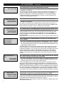
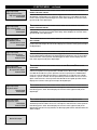
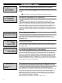
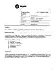
Example of alarms
If an alarm occurs, the
controller (if enabled).
buttom will glow red, and a buzzer will sound if a remote display panel is connected to the
Step 1:
**ALARM**
B1 SENSOR ERROR
OUTSIDE TEMPERATURE
ALARMED@-hr:min.mm/dd
Step 2:
Step 3:
Step 4:
…ALARM OPTIONS…
Press UP to review.
Press Esc to exit.
Press ALARM to RESET
OR
Press the Alarm
button once. This will disable the buzzer and
display which alarms have occurred.
Scroll down through the alarm screens if more than one has occurred.
Use the arrow buttons or alarm button to scroll through the alarms.
Note which alarms occurred and at what time.
Scroll down until the “Alarm Options” screen is displayed.
Step 5:
Press the Esc
button to exit without resetting the alarms.
In this mode the unit will remain operational, as long as the alarm is
non-fatal.
Non-fatal alarms = dirty filters, sensor failure…
Fatal alarms = airflow loss…
Step 6:
Press the Alarm
button to reset the alarms. If the alarm button
stops glowing red, the alarm has been cleared. No action is required.
(Sometimes a sensor can jump out of range for a short period of time,
causing an alarm. The sensor is probably OK, as long as the sensor
does not continually alarm and the displayed value looks reasonable).
If the alarm signals again, the problem still exists and action needs to
be taken. Fix the condition that has caused the alarm.
Step 7:
List of possible alarms
SUPPLY AIR AL:
Indicates a loss of airflow in the supply fan
Alarm & Shutdown
EXHAUST AIR AL:
Indicates a loss of airflow in the exhaust fan
Alarm & Shutdown
DIRTY WHEEL AL:
Indicates a buildup of pressure across the energy recovery wheel
WHEEL ROTATION AL:
DIRTY FILTER AL:
COMPRESSOR TRIP AL:
AC LOCKOUT AL:
MB1 FAIL:
MB2 FAIL:
Indicates
Indicates
Indicates
Indicates
Indicates
set point
Indicates
Indicates
a failure of the outside air temperature sensor
a failure of the supply air temperature sensor
Alarm
Alarm
MB3 FAIL:
Indicates a failure of the after cooling coil air temperature sensor
Alarm
SUPPLY LOW LIMIT AL:
a wheel rotation failure
a buildup of pressure across the filters
a high or low refrigerant pressure
either the low pressure or high pressure switch are open
a discharge temperature lower than the supply low limit
Alarm
Alarm
Alarm
Alarm & Compressor Shutdown
Alarm & Compressor Shutdown
Alarm & Shutdown
3
MAIN MENU / ESC BUTTON
Access the Main Menu by pressing the
key. Scroll through the menu screens using the
keys.
All controller menus are accessed through the Main Menu. See below for description of each menu. Refer to the page
references for additional details about each menu. For details on the Program Menu, see page 17.
SCREEN DESCRIPTION
Press (ENTER) to go to
*UNIT STATUS* menu.
Press (down) for more
menu options.
Press (ENTER) to go to
*SET POINTS* menu.
Press (up or down) for
more menu options.
Press (ENTER) to go to
*OVERRIDES* menu.
Press (up or down) for
more menu options.
Press (ENTER) to go to
*I/O SETUP* menu.
Press (up or down) for
more menu options.
The UNIT STATUS menu allows the user to view real time conditions of the unit.
Conditions that are displayed include:
• Temperature Sensors
• Reheat
• Compressors
• Fan Operation
• Heating
• Preheater
• Energy Recovery Wheel Operation • Cooling
For additional information, please refer to page 5
The SET POINTS menu allows the user to make adjustments to set points. The
adjustable set points relate to:
• Heating
• Economizer Mode
• Cooling
• Supply Air Low Limit
• Dehumidification
• Wheel Defrost
The factory programmed default settings may need to be adjusted to achieve optimum
performance for the specific application.
For additional information, please refer to page 7
The OVERRIDES menu is for start-up/commissioning and troubleshooting the unit.
Components that can be overriden within the system are:
• Frost Control Preheater
• Energy Wheel
• Heating
• Hot Gas Reheat
• Cooling
For additional information, please refer to page 10
The I/O SETUP menu allows the user to view the status of the digital and analog
inputs and outputs of the DDC controller. In addition, adjustments can be made to
recalibrate sensors and change input and output parameters.
For additional information, please refer to page 12
Press (ENTER) to go to
*CLOCK SETUP* menu.
Press (up or down) for
more menu options.
The CLOCK SETUP menu shows the settings for the internal time clock. The Clock
Setup menu is capable of:
• Setting up occupied / unoccupied modes
• Adjusting the time and date
For additional information, please refer to page 15
Press (ENTER) to go to
*MISC INFO* menu.
Press (up or down) for
more menu options.
The MISC INFO menu displays the version of the program and the DDC Code
programmed. The DDC Code provides details of how the unit was ordered and intended
to operate. Both the program version and the DDC Code are required when contacting
the factory for assistance.
For additional information, please refer to page 16
Press (ENTER) to go to
*UNIT ON/OFF* menu.
Press (up or down) for
more menu options.
- - End of MAIN MENU - Hrs:min:sec
month/day/year
4
ADDITIONAL INFORMATION
The UNIT ON/OFF menu allows the user to turn the unit on and off from the
controller.
For additional information, please refer to page 16
UNIT STATUS MENU
Access the UNIT STATUS menu through the Main Menu. Scroll through the menu screens using the
keys. Screens with a dashed line border are dependent upon an optional accessory and may not
always appear.
“STATUS LINE”
System Status
hr:min:sec
mm/dd/yyyy
THE STATUS LINE
DISPLAYS WHICH MODE THE UNIT IS IN .
Possible modes include:
A. Initial Delay
B. Opening Dampers
C. Exhaust Fan Starting
D. Supply Fan Starting
E. System On
F. Defrost Mode Active
G. Sys On-Economizer
H. Sys On-Heating
I. Sys On-Cooling
“STATUS LINE”
Outside: 000. 0º F
Supply: 000. 0º F
Cold Coil: 000. 0º F
THE
“STATUS LINE”
Room: 000. 0º F
THE
J.
K.
L.
M.
N.
O.
P.
Q.
Sys On-Dehumidifying
Sys On-Dehum & Reheat
Unoccupied-Unit Off
Unoccupied-Heating
Unoccupied-Cooling
Manual Override!!
Remote Off
Press Alarm Button!
TEMPERATURES ON THIS SCREEN DISPLAY REAL-TIME CONDITIONS FROM THE
SENSORS IN THE UNIT.
After a period of inactivity (approximately 3 minutes), the controller will revert to this
screen.
TEMPERATURE ON THIS SCREEN REPRESENTS THE REAL-TIME CONDITIONS
BASED ON THE SENSOR IN THE ROOM .
This screen only appears if the room supply temp reset sensor is wired into B4 and
BC4 on the controller.
“STATUS LINE”
Supply Fan:On
Exhaust Fan:On
THE
THE
CONTROLLER DISPLAYS THE RETURN SIGNAL THAT IS BEING RECEIVED FROM
AND E XHAUST FANS .
SUPPLY
On indicates the fan is running. In most modes of operation, both fans will be On. There
are three modes in which one fan may be Off while the other is On. 1) Start-up of the
unit, 2) Timed exhaust frost control, and 3) Unoccupied, 100% return air mode. Other
than these three modes, if one fan is Off and the other is On, there may be a problem.
ENERGY
“STATUS LINE”
Energy Recovery
Wheel: 000% Speed
“STATUS LINE”
Cooling Control:000%
Compressor: ##
RECOVERY WHEEL OPERATION IS DISPLAYED AS A PERCENT.
If the unit does not contain a VFD on the wheel motor, then 0% = OFF; 100% = ON. If
the unit contains a VFD to modulate the wheel speed for frost control or economizer
operation, this screen will display the percentage directly proportional to the 0-10 VDC
signal being sent to the wheel VFD
0 VDC = 000%, 10 VDC = 100%
To override: ‘MANUAL OVERRIDE’ menu >Energy Recovery Wheel Override
THIS
SCREEN DISPLAYS THE COOLING CONTROL AS A PERCENTAGE .
This screen only appears if a cooling option is provided.
Chilled Water Coil: The Loop Output % is directly proportional to a 0-10 VDC signal
000% = 0 VDC - Full Closed; 100% = 10 VDC - Full Open
000% = 2 VDC - Full Closed; 100% = 10 VDC - Full Open
The cooling control valve can either be 0-10 VDC or 2-10 VDC depending upon the
valve installed. The user may need to adjust the I/O SETUP menu so that 0-100%
cooling correlates with a 2-10 VDC signal (0-10 VDC is default).
To adjust: ‘I/O SETUP’ menu> Analog Output Y3
DX Coil: Cooling Control displays compressor engagement as a percent
• 000% Compressors OFF
(1 or 2 compressor system)
• 050% First compressor ON
(2 compressor system)
• 100% First & second compressor ON
(2 compressor system)
First compressor ON
(1 compressor system)
5
UNIT STATUS MENU - continued
“STATUS LINE”
Cooling Control:000%
Compressor: ##
“STATUS LINE”
Hot Gas Reheat:000%
Heater Control:000%
THIS
SCREEN DISPLAYS THE COOLING CONTROL AS A PERCENTAGE (CONTINUED)
The Compressor line indicates which compressor is ON
1
First compressor
2
Second compressor
12
Both compressors
To override: ‘MANUAL OVERRIDE’ menu >Cooling Loop Override
THIS
SCREEN DISPLAYS THE CURRENT REHEAT AND HEAT OPERATION OF THE UNIT.
Hot Gas Reheat only appears if provided with unit.
Hot Gas Reheat operation is on/off control displayed as a percent.
100% is ON and 000% is OFF
To override: ‘MANUAL OVERRIDE’ menu >Hot Gas Reheat Override
For Modulating Hot Gas Reheat Control:
000% is OFF and 001% HGRH is ON and the airflow damper is modulating
between 4 VDC and 10 VDC.
Heater Control displays the real-time percent heater output and is directly proportional
to a 0-10 VDC signal provided by the discharge temperature sensor.
To override: ‘MANUAL OVERRIDE’ menu >Heating Loop Override
Electric Heater: The Heater Control % is directly proportional to a 0-10 VDC signal
being sent to the SCR controller in the electric heater’s control center.
000% = 0 VDC = 0 kW output
100% = 10 VDC = Maximum kW output
Indirect Gas Furnace: The Heater Control % is directly proportional to a 0-10 VDC
signal being sent to the indirect gas furnace control board. The first stage is full ON at a
1% Heater Control. Once the Heater Control reaches 50%, the second stage modulates
between 50% and 100% output.
001 – 049%
First stage: ON, Second stage: OFF
050 – 100%
First stage: ON, Second stage: Modulating between
50% and 100% output
Hot Water Heater: The heating control valve (supplied by others) can either be 0-10 VDC
or 2-10 VDC depending upon what valve is installed. The user may have to adjust the
‘I/O SETUP’ menu so that a 0-100% heating correlates with a 2-10 VDC signal (0-10 VDC
is default).
To adjust: ‘I/O SETUP’ menu >Analog Output Y2
“STATUS LINE”
Energy recovery
wheel differential
pressure is: Normal
“STATUS LINE”
Preheat heater: OFF
THE
UNIT CONTAINS A WHEEL PRESSURE DROP SENSOR TO INDICATE WHETHER
THE PRESSURE ACROSS THE WHEEL IS NORMAL OR H IGH .
This screen only appears if a frost control method was provided.
A status of High is an indication of frost accumulation. The pressure set point is
adjustable on the wheel pressure switch.
THIS
SCREEN INDICATES WHETHER THE ELECTRIC PREHEAT FROST CONTROL IS ON
OR OFF.
This screen only appears if Electric Preheat frost control was provided.
To override: ‘MANUAL OVERRIDE’ menu >Energy Recovery Wheel Preheater
End of status menu
6
SET POINTS MENU
Access the SET POINTS menu through the Main Menu. Scroll through the menu screens using the
***ACCESS DENIED***
Enter Password:0000
WRONG PASSWORD
keys.
THIS SCREEN CAN BE LOCKED TO PREVENT TAMPERING WITH THE SETTINGS .
FROM THE FACTORY, ACCESS IS NOT PASSWORD PROTECTED TO ALLOW QUICKER
START- UP.
To set the password, go to the ‘PROGRAM’ menu by pressing the
button. Once
there, scroll down until you arrive at the Change Password screen. The ‘Level 1’
password protects the ‘SET POINTS’ menu.
Unit Set Points
Supply Air Reset
Outside
Supply
060.0ºF --->
072.0ºF
070.0ºF --->
060.0ºF
THIS
SCREEN DISPLAYS THE CURRENT DISCHARGE SET POINT FOR THE UNIT,
WHICH IS THE TEMPERATURE THE UNIT IS TRYING TO DISCHARGE .
If there is no room temperature sensor (nothing wired to terminals B4 and BC4 on
controller), the controller changes the supply air discharge temperature of the unit
based on the outdoor air temperature (refer to outdoor air reset function below). With
no room temperature sensor, a BMS can override the controller and input directly the
desired supply temperature for the unit.
If a room temperature sensor is connected to terminals B4 and BC4 on the DDC
controller, then the supply temperature of the unit is adjusted based on the difference
between the actual room temperature (reading from the room temperature sensor) and
the desired room temperature which is programmed into the controller (refer to Room
Set Point screen below). With a room temperature sensor connected to the controller, a
BMS can override the controller and input directly the desired room set point. This new
desired room set point will be used for comparing with the actual room temperature.
To activate the BMS override temperatures, refer to the Program Menu and change the
Set Point Source screen to BMS Interface.
THESE
PARAMETERS DICTATE THE OPERATION OF THE OUTDOOR AIR RESET
FUNCTION IN THE CONTROLLER .
This screen does not appear when the room supply temp sensor is wired into
terminals B4 and BC4 on the controller.
The unit monitors the outdoor air temperature and adjusts the desired supply
temperature accordingly. For example, when the outdoor air is below 60.0ºF, the
controller will change the Supply set pt to 72.0ºF. If the outdoor air is above 70.0ºF, the
controller would change the Supply set pt to 60.0ºF. If the outdoor air temperature is
between 60.0ºF and 70.0ºF, the Supply discharge temperature changes according to
the outdoor air reset function. A visual representation of the outdoor air reset function
is shown.
Desired Supply Temperature
Outdoor Air Reset Function
72.0°F
Discharge Temperature (°F)
Supply set pt
is currently=###.#ºF
This set pt is reset
up/down by the DDC.
73°
71°
69°
67°
65°
63°
61°
Desired Supply Temperature
60.0°F
59°
57°
55°
55°
60°
65°
70°
75°
Outside Air Temperature (°F)
7
SET POINTS MENU - continued
Room Set Point
Local set pt:72.0ºF
THIS
Supply Reset Limits
Supply Min:055.0ºF
Supply Max:090.0ºF
THIS
Cold coil set point
Normal Mode:55.0ºF
Dehumidify:50.0ºF
Active set pt:55.0ºF
Unit will energize
to maintain unocc
room set points.
Differential:5.0ºF
8
SCREEN DISPLAYS THE SPACE TEMPERATURE SET POINT.
This screen only appears if the room supply temp sensor is wired into terminals B4
and BC4 on the controller.
The unit will reset the unit discharge temperature up and down to maintain the local
set point. If a BMS is interfaced with the controller, the user has the capability to
dictate the desired Room set point through the BMS. The screen will show a BMS
set point and an Active set point. The Active set point is the room temperature the
controller is currently trying to maintain.
SCREEN DISPLAYS THE MINIMUM AND MAXIMUM SUPPLY AIR TEMPERATURE.
This screen only appears if the room supply temp sensor is wired into terminals B4
and BC4 on the controller.
The supply air temp will integrate SLOWLY down (Pl loop) towards this minimum set
point to maintain room temperature. The supply air temp will integrate SLOWLY up (PI
loop) towards this maximum set point to maintain room temperature.
THIS
SCREEN DISPLAYS THE TEMPERATURE SET POINTS FOR THE COOLING COILS .
This screen only appears if a Cooling option was provided with the unit.
The Normal Mode set point is the after coil temperature the unit will maintain under
standard operation. If a Humidistat was provided with the unit, the Dehumidify set
point is the temperature the cooling coil will discharge on a call for dehumidification
from a humidistat.
The Active set pt is the temperature that the unit is currently trying to maintain off the coil.
THIS
SCREEN DISPLAYS THE
COOLING MODES .
DIFFERENTIAL
SET POINT FOR THE HEATING AND
This screen only appears if the 7th character in the DDC Code is set to 1, meaning
the “Cycle on Room” unoccupied mode was chosen. Operation in “Cycle on Room”
unoccupied mode requires the room sensor be wired into terminals B4 and BC4 , and
a night setback damper in the unit.
This differential acts as a hysteresis to keep the heating and cooling from cycling too
often. For example, on a call for heating (room temp. set point - differential, 65.0ºF5.0ºF=60.0ºF) supply fan cycles on. Unit cycles off when the room temperature reaches
the Unoccupied room set point (65.0ºF, adjustable). For cooling, the differential is
added to the Unoccupied room set point (85.0ºF+5.0ºF=90.0ºF) to cycle supply fan
on. Unit cycles off when the room temperature reaches Unoccupied room set point
(85.0ºF).
Unoccupied room set
point
Heating:65.0ºF
Cooling:85.0ºF
THIS
Heater Lockout
Lockout heater when
outside air >:70.0ºF
Hysteresis=02.0ºF
THIS
SCREEN DISPLAYS THE ROOM SET POINTS WHICH DICTATE THE UNIT HEATING
AND COOLING OPERATION DURING UNOCCUPIED MODE .
This screen only appears if the “Cycle on Room” unoccupied mode was chosen
for the unit. A room sensor temp. must be wired into terminals B4 and BC4 on the
controller, and the unit must have a night setback damper.
In Unoccupied Mode when the temperature falls below the room Heating set point
(hysteresis = 5ºF), the supply fan and unit heating will turn on. Unit will discharge the
Supply Max temperature per the ‘Supply Reset Limits’ screen above until the room set
point is satisfied. Unit will then shut down. In Unoccupied Mode when the temperature
rises above the Cooling set point (hysteresis = 5ºF), the supply fan and unit cooling will
turn on. Unit will discharge the Supply Min temperature per the ‘Supply Reset Limits’
screen above until the room temperature set point is satisfied. Unit will then shut down.
CONTROLLER WILL LOCK THE HEATING SECTION OFF WHEN THE OUTDOOR AIR
TEMPERATURE IS ABOVE THE SET POINT (FACTORY DEFAULT = 70ºF).
This screen only appears if a Heating option was provided with the unit.
A Hysteresis of 2ºF helps to avoid short cycling of the heater. The hysteresis is similar
to a deadband above and below the Lockout heater set point.
(Example: If Lockout = 70ºF, heating is locked out for outside air conditions above 72ºF
and enabled below 68ºF).
SET POINTS MENU - continued
Cooling Lockout
Lockout cooling when
outside air <:55.0ºF
Hysteresis=02.0ºF
Lockout dehumidification until outside
air is:10.0ºF above
cold coil set point
Economizer Lockout
Lockout econo when
outside air <:40.0ºF
Hysteresis=02.0ºF
Supply air low limit
alarm when supply is
less than: 35.0ºF
Alarm delay:300s
THIS
CONTROLLER WILL LOCK THE COOLING SECTION OFF WHEN THE OUTDOOR AIR
TEMPERATURE IS BELOW THE COOLING LOCKOUT SET POINT
(FACTORY DEFAULT = 55ºF).
This screen will only appear if Cooling was provided with the unit.
There is a built in hysteresis of 2ºF which prevents the compressors from short cycling.
The hysteresis is similar to a deadband above and below the lockout set point.
(Example: If Lockout = 55ºF, cooling is locked out below 53ºF and end enabled above
57ºF outside air temp).
THIS
SCREEN DISPLAYS THE TEMPERATURE DIFFERENCE AT WHICH THE
DEHUMIDIFICATION ON THE UNIT IS LOCKED OUT (FACTORY DEFAULT = 10ºF).
This screen will only appear if cooling was provided with the unit.
This setting prevents the unit from operating in dehumidification mode when outdoor
air conditions are relatively cool. For example, if the cold coil set point is 55ºF,
dehumidification mode cannot operate until the outdoor air is at least 65ºF.
ECONOMIZER LOCKOUT
PREVENTS THE UNIT FROM GOING INTO ECONOMIZER
MODE WHEN OUTDOOR AIR CONDITIONS ARE TOO COLD .
This screen only appears if economizer was provided with the unit.
The lockout prevents outdoor air from 1) entering the space at too cold of a
temperature or 2) entering heating and cooling coils at conditions that could freeze
the coils. Built-in hysteresis of 2ºF. The hysteresis is similar to a deadband above and
below the lockout set point.
(Example: If Lockout = 40ºF, economizer is locked out below 38ºF and enabled above
42ºF outside air temp)
THIS
SCREEN DISPLAYS WHAT THE LOW TEMPERATURE LIMIT IS FOR THE UNIT.
If the unit supply discharge temperature falls below Supply Air Low Limit set point
(factory default 35F) for a period of time (factory default 300 sec) the unit will shut down
and an alarm will be signaled. The purpose of the Discharge Freeze Protection is to
protect the building and contents from low temperature supply air. It is NOT designed
to protect the Energy Recovery unit.
If the Energy Recovery unit does not have CW or HW coils (has only no heat, IG heat,
electric heat, no cooling, or Dx cooling) it should not need additional protection from
freezing. If the Energy Recovery unit does have CW or HW coils, please contact the
factory for more details.
Defrost
Allow wheel defrost
mode when outside
is less than: 05.0ºF
THIS
SCREEN DISPLAYS THE TEMPERATURE AT WHICH THE UNIT WILL BEGIN FROST
CONTROL MODE .
This screen only appears if a frost control method was provided with the unit.
The energy wheel transfers both latent and sensible energy at relatively similar
efficiencies. Therefore, in most applications where indoor mositure levels are
below 35% RH, frost typically will not occur on the energy wheel until outdoor air
temperatures are below 5ºF. Consult the factory if you have any concerns regarding
your specific application.
End of Set Points
9
MANUAL OVERRIDE MENU
Access the OVERRIDES menu through the Main Menu. Scroll through the menu screens using the
***ACCESS DENIED***
Enter Password:0000
WRONG PASSWORD
keys.
THIS SCREEN CAN BE LOCKED TO PREVENT TAMPERING WITH THE SETTINGS .
FROM THE FACTORY, ACCESS IS NOT PASSWORD PROTECTED TO ALLOW QUICKER
START- UP.
To set the password, go to the ‘PROGRAM’ menu by pressing the
button. Once
there, scroll down until you arrive at the Change Password screen. The ‘Level 1’
password protects the ‘OVERRIDES’ Menu.
THE OVERRIDE MENU
IS USED FOR MANUAL OVERRIDE OF THE CONTROL LOOP.
Manual override of
control loops
(Unit must be ON)
To manualy override a function, change the status “AUTO” to “MANUAL”.
Energy recovery
wheel override
Wheel:AUTO
Wheel:OFF
Energy recovery
wheel override
Wheel:AUTO
% Speed:000%
Cooling loop
override.
Cooling:AUTO
Loop output:000%
10
THE USER CAN OVERRIDE THE ENERGY RECOVERY WHEEL OPERATION .
This screen only appears if there is not a VFD operating the energy wheel.
When the wheel is in MANUAL mode, use the arrow buttons to turn the wheel ON or
OFF.
THE USER CAN OVERRIDE THE ENERGY RECOVERY WHEEL OPERATION .
This screen only appears if the Modulating Wheel Frost Control or Modulating Wheel
Economizer was provided with the unit.
When the wheel is in MANUAL mode, use the arrow buttons to change the % Speed to
vary the wheel rotational speed. The % Speed is directly proportional to a 0-10V signal
being sent to the energy wheel VFD.
THE USER CAN OVERRIDE THE COOLING LOOP OPERATION .
This screen only appears if a cooling option was provided with the unit.
When the cooling loop override is in MANUAL mode, use the arrow buttons to vary the
% output.
Chilled Water Coil: Loop Output % is directly proportional to a 0-10 VDC or 2-10 VDC
signal.
000% = 0 VDC = Full Closed; 100% = 10 VCD = Full Open
000% = 2 VDC = Full Closed; 100% = 10 VCD = Full Open
2 Stage DX Coil: Loop Output displays compressor engagement as a percent.
000% Compressor OFF
050% First Compressor ON
100% First & Second Compressor ON
Second stage will NOT disengage until Loop Output is below 50%
First stage will NOT disengage until Loop Output is 0%
1 Stage DX Coil: Loop Output displays compressor engagement as a percent.
000% Compressor OFF
100% Compressor ON
In a single stage DX cooling system, the compressor engages when the Loop Output is
100%. Once the compressor is engaged, it will not disengage until the Loop Output is
0%.
Note: Damage can occur to compressors from short-cycling, therefore the controller
has built-in time delays which are effective upon each engagement of a compressor.
MANUAL OVERRIDE MENU - continued
Heater loop
override.
Heating:AUTO
Loop output:000%
Hot gas reheat loop
override
Hot gas: AUTO
Hot gas: OFF
Hot gas reheat loop
override
Hot gas: AUTO
Loop output:000%
Energy recovery wheel
preheater
Preheater:AUTO
Preheater:OFF
THE USER CAN OVERRIDE THE HEATING OPERATION .
This screen only appears if a Heating option was provided with the unit.
To manually override the heating, adjust the Heating status from AUTO to MANUAL.
When the Heating loop override is in MANUAL mode, use the arrow buttons to vary the
% output.
Hot Water Coil: The Loop Output % is directly proportional to a 0-10 VDC or 2-10 VDC
signal being set to the hot water valve.
000% = 0 VDC = Full Closed; 100% = 10 VDC = Full Open
000% = 2 VDC = Full Closed; 100% = 10 VDC = Full Open
Electric Heater: The Loop Output % is directly proportional to a 0-10 VDC signal being
sent to the SCR controller in the electric heater’s control center.
000% = 0 VDC = 0 kW output
100% = 10 VDC = Maximum kW output
Indirect Gas Furnace: The Heater Control % is directly proportional to a 0-10 VDC
signal being sent to the indirect gas furnace control board. Where the first stage is full
ON at a 1% Heater Control. Once the Heater Control reaches 50%, the second stage
modulates between 50% and 100% output.
001% - 049%: First stage: ON, Second stage: OFF
050% - 100%
First stage: ON, Second stage: Modulating between 50%
and 100% output
THE USER CAN OVERRIDE THE HOT GAS REHEAT OPERATION .
This screen only appears if the On/Off Hot Gas Reheat option was provided with the
unit.
To manually override the Hot gas reheat loop, adjust the Hot gas status from AUTO to
MANUAL. When the Hot Gas Reheat loop is in MANUAL mode, use the arrow buttons
to open or close the HGRH valve (ON = Open, OFF = Closed).
THE USER CAN OVERRIDE THE HOT GAS REHEAT OPERATION .
This screen only appears if the Modulating Hot Gas Reheat option was selected with
the unit.
To manually override the Hot gas reheat loop, adjust the Hot gas status from AUTO to
MANUAL. When the Hot Gas Reheat loop is in MANUAL mode, press the up and down
arrow to vary the Loop output %. The Loop output % is directly proportional to a 0-10
VDC signal being sent to the HGRH controller.
000% = 0 VDC = Full Closed
100% = 10 VDC = Full Open
THE USER CAN OVERRIDE THE ENERGY RECOVERY WHEEL PREHEATER .
This screen only appears if the Electric Preheat Frost Control option was provided
with the unit.
To manually override the Electric Preheater, adjust the Preheater status from AUTO to
MANUAL. When the Energy Recovery wheel preheater is in MANUAL mode, use the
arrow buttons to turn the Electric Preheater ON or OFF.
End of manual
overrides
11
I/O SETUP MENU
Access the I/O SETUP menu through the Main Menu. Scroll through the menu screens using the
keys.
Sensor Calibration: Measure the actual temperature and find the difference from the Sensor Temp
(uncalibrated). This difference becomes the Offset and once the Offset is input to the
controller, the Actual Temp should match the actual measured temperature.
***ACCESS DENIED***
Enter Password:0000
WRONG PASSWORD
Setups for DDC
Analog & Digital
Inputs/Outputs
THIS SCREEN CAN BE LOCKED TO PREVENT TAMPERING WITH THE SETTINGS .
FROM THE FACTORY, ACCESS IS NOT PASSWORD PROTECTED TO ALLOW QUICKER
START- UP.
To set the password, go to the ‘PROGRAM’ menu by pressing the
button.
Once there, scroll down until you arrive at the Change Password screen. The ‘Level 2’
password protects the ‘I/O SETUP’ menu.
THE ‘I/O SETUP’
INPUT/OUTPUTS .
MENU IS USED TO SET UP THE ANALOG
&
DIGITAL
NOTE: The wiring terminal for each I/O is displayed in the respective screens.
Sensor Temp is the sensor’s uncalibrated output.
Offset is for calibrating the sensor.
Actual Temp is the new calibrated sensor output.
B1 Outside:NTC
Sensor Temp:
000.0ºF
Offset =
00.0ºF
Actual Temp:
000.0ºF
THIS
SCREEN DISPLAYS THE OUTSIDE AIR TEMPERATURE ENTERING THE UNIT.
B2 Supply:NTC
Sensor Temp:
Offset =
Actual Temp:
THIS
SCREEN DISPLAYS THE SUPPLY DISCHARGE TEMPERATURE .
THIS
SCREEN DISPLAYS THE AFTER COOLING COIL TEMPERATURE .
000.0ºF
00.0ºF
000.0ºF
B3 Cold Coil:NTC
Sensor Temp:
000.0ºF
Offset =
00.0ºF
Actual Temp:
000.0ºF
B4 Room Temp:NTC
Sensor Temp:
000.0ºF
Offset =
00.0ºF
Actual Temp:
000.0ºF
B4 Input
Max cooling demand.
Input Status:Open
12
This screen only appears if a cooling system was selected.
THIS
SCREEN DISPLAYS THE ROOM TEMPERATURE .
This screen only appears if the room supply sensor is wired between B4 and BC4 on
the controller.
THIS
SCREEN DISPLAYS THE STATUS OF THE DIGITAL INPUT TO TERMINAL
B4.
This screen only appears if the room supply sensor is NOT wired between B4 and
BC4 on the controller.
When the Input Status is Open, the unit will operate normally and adjust the discharge
temperature based on outdoor air temperature. When the Input Status is Closed (in the
case of a digital input, ie. Thermostat), this indicates that a digital call for cool is being
received by the controller. The controller then overrides the outdoor air temperature
discharge control and sends the supply temperature set point to the supply reset
minimum temperature (Max cooling: 55ºF,adj. in ‘SET POINTS’ menu).
I/O SETUP MENU - continued
B5 Dehumidify:ON/OFF
Input Status:Open
THIS
SCREEN DISPLAYS THE STATUS OF THE DEHUMIDIFICATION MODE .
This screen only appears if there is a humidistat wired to terminals B5 and BC5 on
the controller.
When the Input Status is Open, there is no call for dehumidification. When the Input
Status is Closed, the cold-coil set point is reset for further dehumidification.
ANALOG OUTPUTS - PARAMETERS
The Analog Output screens allow the user to adjust the analog outputs for the energy recovery wheel, heating, cooling, and
hot gas reheat operation. The factory defaults are provided in the screens shown and are designed to operate with any
factory supplied components. Chilled water valves, hot water valves, DX distributors, or HGRH valves provided by others
may require adjustments to the following screens to properly operate the components.
Analog output Y1
Energy Recovery Wheel
Output
0% --> 100%
SIGNAL
00.0V
10.0V
Analog output Y2
Heater
Output
0% --> 100%
SIGNAL
00.0V
10.0V
THIS
SCREEN DISPLAYS THE CORRELATION BETWEEN THE A NALOG OUTPUT
AND THE VOLTAGE SIGNAL FOR THE ENERGY RECOVERY WHEEL .
%
***DO NOT ADJUST THIS SETTING***
This screen may relate to on/off or modulating control depending upon what
accessories were ordered with the unit. The energy recovery wheel is factory-installed
and programmed.
THIS
SCREEN DISPLAYS THE CORRELATION BETWEEN THE A NALOG OUTPUT
AND THE VOLTAGE SIGNAL FOR THE HEATING (IE . 60% = 6 VDC).
%
This screen only appears if Heating was provided with the unit.
The Output and SIGNAL will provide the appropriate control of a hot water coil, electric
heater, or indirect gas furnace. User can change the SIGNAL range if required. Factory
defaults are 0-10 VDC.
NOTE: This is where the user would adjust for a Heating Control Valve that is
2-10 VDC rather than 0-10 VDC.
Analog output Y3
Cooling
Output
0% --> 100%
SIGNAL
00.0V
10.0V
THIS
SCREEN DISPLAYS THE CORRELATION BETWEEN THE A NALOG OUTPUT
AND THE VOLTAGE SIGNAL FOR THE HEATING (IE . 60% = 6 VDC).
%
This screen only appears if Chilled Water was provided with the unit.
The Output and SIGNAL will provide the appropriate control of a chilled water coil.
User can change the SIGNAL range if required. Factory defaults are 0-10 VDC.
NOTE: This is where the user would adjust for a Cooling Control Valve that is
2-10 VDC rather than 0-10 VDC.
Analog output Y4
Hot Gas Reheat
Output
0% --> 100%
SIGNAL
00.0V
10.0V
THIS
SCREEN DISPLAYS THE CORRELATION BETWEEN THE
AND THE VOLTAGE SIGNAL FOR THE HOT GAS REHEAT (IE .
A NALOG OUTPUT %
60% = 6 VDC).
This screen only appears if HGRH was provided with the unit.
The Output and SIGNAL will provide the appropriate control of a on/off or modulating
hot gas reheat coil. User can change the SIGNAL range if required. Factory defaults are
0-10 VDC.
DIGITAL INPUTS - PARAMETERS
WARNING!
The following screens show the factory defaults for each parameter. Do NOT change parameters unless you are
absolutely certain the parameter needs to be modified. Unit will not function properly and damage may occur
to the unit if the parameters do not match the contact requirements of the components.
Digital Input (ID1)
Supply proving switch
Alarm: Open
Status:Closed
THIS
SCREEN DISPLAYS THE ALARM STATUS MODE OF THE SUPPLY PROVING
SWITCH .
When the Supply proving switch alarm is triggered, the fan is not seeing airflow and the
unit will shutdown and alarm. The Alarm parameter allows the user to select Open or
Closed for the contact position that will trigger the alarm. Status displays the real time
status (Open/Closed) of the digital input.
NOTE:
The controller is only monitoring the contact position -- Not the actual
operation of the fan.
13
I/O SETUP MENU - continued
Digital Input (ID2)
Wheel pressure switch
High pressure=Closed
Status:Open
Digital Input (ID3)
Wheel rotation alarm
Alarm:Closed
Status:Open
Digital Input (ID4)
Unit ON/OFF control
Unit ON when:Closed
Status:Open
Digital Input (ID5)
Exhaust proving switch
Alarm:Open
Status:Closed
Digital Input (ID6)
Occupied/Unoccupied
Occupied when:Open
Status:Closed
Digital Input (ID7)
Dirty filter switch
Alarm:Closed
Status:Open
Digital Input (ID8)
Compressor limits
Alarm:Open
Status:Closed
End of I/O setups
14
THIS
SCREEN DISPLAYS THE ALARM STATUS MODE OF THE ENERGY RECOVERY
WHEEL PRESSURE SWITCH .
When the Wheel pressure switch alarm is triggered, the wheel has excessive frost or
dirt build-up. The High pressure parameter allows the user to select Open or Closed
for the contact position that will trigger the alarm. Status displays the real time status
(open/closed) of the digital input.
THIS
SCREEN DISPLAYS THE ALARM STATUS MODE OF THE ENERGY RECOVERY
WHEEL ROTATION SENSOR .
When the Wheel rotation alarm is triggered, the wheel has stopped rotating. Refer to
‘PROGRAM’ menu for wheel rotation alarm delay. Status displays the real time status
(open/closed) of the digital input.
THIS
SCREEN DISPLAYS THE STATUS MODE OF THE REMOTE INPUT FOR UNIT ON /
OFF CONTROL .
The Unit ON when parameter allows the user to select Open or Closed for the contact
position that will energize the unit. Status displays the real time status (open/closed) of
the digital input.
THIS
SCREEN DISPLAYS THE ALARM STATUS MODE OF THE EXHAUST FAN .
When the Exhaust proving switch alarm is triggered, the fan is not seeing airflow and
the unit will shutdown and alarm. The Alarm parameter allows the user to select Open
or Closed for the contact position that will trigger the alarm. Status displays the real
time status (open/closed) of the digital input.
THIS
SCREEN DISPLAYS THE ALARM STATUS OF THE
OPERATION .
OCCUPIED/UNOCCUPIED
While in Input ID6 mode, (refer to ‘PROGRAM’ menu) the input from ID6 will send the
unit into occupied or unoccupied mode. If in BMS or Time Clock mode, a 24 VDC input
from ID6 will override the system operation from unoccupied (refer to ‘TIME CLOCK’
menu for actual override time period) to occupied (but not occupied to unoccupied)
mode for a specific override. The Occupied when parameter allows the user to select
Open or Closed for the contact position that will indicate Occupied operation. Status
displays the real time status (open/closed) of the digital input.
THIS
SCREEN DISPLAYS THE ALARM STATUS MODE OF THE DIRTY FILTER SWITCH .
The Alarm parameter allows the user to select Open or Closed for the contact position
that will trigger the alarm. Status displays the real time status (open/closed) of the
digital input.
THIS
SCREEN DISPLAYS THE ALARM STATUS MODE OF THE COMPRESSORS .
This screen only appears if DX cooling was provided in the unit.
The Alarm parameter allows the user to select Open or Closed for the contact position
that will trigger the alarm. Status displays the real time status (open/closed) of the
digital input. Based on factory defaults, the DX staging will lockout and alarm when the
Status is Open.
TIME CLOCK MENU
Access the CLOCK SETUP menu through the Main Menu. Scroll through the menu screens using the
keys.
IMPORTANT! User must select one of the three options for the Source in the
Unoccupied mode setup screen in the ‘PROGRAM’ menu. The Source represents the
means by which Occupied and Unoccupied modes are determined.
Option 1: Input ID6 – typically used with a remote time clock (Default)
Option 2: BMS – can be overridden by a separate input to ID6
Option 3: Internal Time Clock – can be overridden by a momentary input to ID6
***ACCESS DENIED***
Enter Password:0000
WRONG PASSWORD
CLOCK
hr:min:sec
(Day of week)
mm/dd/yyyy
Time/Date/Day Setup
Press ENTER to reset
the internal clocks
time, date & day
Occ-Unocc Override
Current Mode:Occ
Override Time:060min
Override:No
THIS SCREEN CAN BE LOCKED TO PREVENT TAMPERING WITH THE SETTINGS .
FROM THE FACTORY, ACCESS IS NOT PASSWORD PROTECTED TO ALLOW QUICKER
START- UP.
To set the password, go to the ‘PROGRAM’ menu by pressing the
button. Once
there, scroll down until you arrive at the Change Password screen. The ‘Level 1’
password protects the ‘TIME CLOCK’ menu.
THE CLOCK SETUP MENU ALLOWS THE USER
OCCUPIED /UNOCCUPIED MODE SETTINGS .
TO ADJUST THE TIME , DATE , AND
User can also override the current occupied/unoccupied mode for a designated period
of time.
Reset clock
Time-00:00:00
Date: 00/00/00 (m/d/y)
Day-NA
Set the time, date & day here. All three must be
set/reset at the same time. When the cursor is in the
upper left corner, press up or down to return to the
clock menu.
CURRENT
MODE DISPLAYS WHETHER THE UNIT IS IN OCCUPIED MODE OR
UNOCCUPIED MODE .
(OCC = OCCUPIED , UNOCC = UNOCCUPIED)
This screen will only appear if the Occupied/Unoccupied ID6 function has been set
to ‘ON’ in the PROGRAM menu under Binary Input Enables.
The controller will allow the user to override from Unoccupied to Occupied mode, but
not vice versa. This can be performed by changing this screen to Yes, or it can also
be done through a momentary 24 VDC input to terminal ID6. After the Override Time
expires, the clock returns to the 7-day schedule.
The following screens only appear if Option 3, the Internal Time Clock function, has been enabled in the Program
Menu.
Enable Occ/Unocc
Mon:Yes Tue:Yes Fri:Yes
Wed:Yes Thu:Yes Sat:Yes
Sun:Yes
THIS
SCREEN ALLOWS THE USER TO ENABLE /DISABLE
EACH DAY OF THE WEEK .
UNOCCUPIED
MODE FOR
Selecting ‘No’ means the unit will operate in an Occupied mode only.
Selecting ‘Yes’ means the unit will operate in an Occupied mode and an Unoccupied
mode.
Enter the desired Occupied/Unoccupied start times for each day (24 hour time scale).
Occupied Unoccup
Mon 06:00 18:00
Tue 06:00 18:00
Wed 06:00 18:00
Occupied Unoccup
Thu 06:00 18:00
Fri
06:00 18:00
Enter the desired Occupied/Unoccupied start times for each day (24 hour time scale).
15
TIME CLOCK MENU - continued
Enter the desired Occupied/Unoccupied start times for each day (24 hour time scale).
Occupied Unoccup
Sat 06:00 18:00
Sun 06:00 18:00
Enter the number of holidays you wish to schedule (up to 15 days can be entered).
Holidays
Holiday = unoccupied
mode for 24 hrs.
# of holidays:00
Holiday #1
Month:01
Day:01
Unoccupied for 24hrs
Holidays must be updated every year!
The internal clock will index into unoccupied mode as long as the date is equal to a
date entered as a holiday (always a 24 hour period).
Example: New Years Day, January 1
End of Clock setup
MISC INFO MENU
Access the MISC INFO menu through the Main Menu. Scroll through the menu screens using the
Greenheck Fan Corp.
ER DDC1 v3.00
DDC Code: GY2A211X
keys.
THIS
SCREEN DISPLAYS THE VERSION OF THE PROGRAM INSTALLED IN THE
CONTROLLER .
If contacting the factory for assistance, record the version of the program and the DDC
Code displayed on this screen.
The DDC was supplied with
a user manual - if missing,
visit www.greenheck.com
End of Information
menu
UNIT ON/OFF MENU
Access the UNIT ON/OFF menu through the Main Menu. Scroll through the menu screens using the
Press (ESC) to exit
Command unit on or
off below.
Command Unit:ON
THE ‘UNIT ON/OFF’
MENU ALLOWS THE USER TO TURN THE UNIT ON AND OFF
FROM THE CONTROLLER , PROVIDED THE R TO G CONTACT IN THE UNIT CONTROL
CENTER IS CLOSED .
Press Enter to highlight ON/Off in the lower right corner.
Press the the
buttons to turn unit ON or OFF.
A remote ON/OFF switch may also be wired into ID4
End of Information
menu
16
keys.
PROGRAM MENU
Access the PROGRAM menu by pressing
key. Scroll through the menu screens using the
keys.
The program button is used to setup the control loops for economizer, defrost, heating, cooling, and reheat
along with defaults for staging, supply reset, time delays, occupied mode, communications, set point source,
temperature scale, and changing passwords. Adjustments to these parameters should be performed by a
qualified technician. (A Level 2 password must be entered to alter any of the factory programming; factory
default is 9998).
***ACCESS DENIED***
Enter Password:0000
WRONG PASSWORD
THIS SCREEN CAN BE LOCKED TO PREVENT TAMPERING WITH THE SETTINGS .
FROM THE FACTORY, ACCESS IS NOT PASSWORD PROTECTED TO ALLOW QUICKER
START- UP.
To set the password, go to the ‘PROGRAM’ menu by pressing the
button. Once
there, scroll down until you arrive at the Change Password screen. The ‘Level 2’
password protects the ‘Program’ menu.
Factory Setup
Consult factory
before altering
Economizer Controller
Integration:300s
Control Band:20ºF
Economizer Setup
Econo on/off times
Minimum ON:300s
Minimum OFF:300s
Supply fan cycling
defrost setup.
Fan off time:005min
Fan on time:030min
Cooling Controller
Integration:300s
Band:20ºF
THIS
SCREEN ALLOWS THE INTEGRATION TIME FOR THE PI CONTROL OF THE
ECONOMIZER AND THE TEMPERATURE BAND AROUND THE SUPPLY SET POINT TO
BE ADJUSTED .
This screen will only appear if an Economizer mode was selected with the unit.
This controller uses a Proportional + Integral type control. The integration time
programmed into the controller is to provide a smooth reaction to conditions, allowing
for less sporadic changes in discharge temperature. To speed up reaction time,
decrease the integration time. For slower reaction time, increase the integration time.
When making adjustments, make them in small increments, and test the system to
determine if the new setting is adequate prior to further adjustment. The band is the
range that the integration will occur between.
Range of Integration = Supply set pt ± Band. ie: 50° F ± 20° F
THIS
SCREEN ALLOWS ADJUSTMENT FOR THE
ECONOMIZER .
MINIMUM ON/OFF
TIMES FOR THE
This screen only appears if ON/OFF economizer was provided with the unit.
These minimum ON and OFF times prevent the energy wheel motor from short cycling
during economizer mode.
THIS SCREEN DISPLAYS THE ON/OFF FAN CYCLE TIMES FOR THE TIMED
EXHAUST FROST CONTROL AND ALLOWS THE USER TO ADJUST THESE
PARAMETERS .
This screen only appears if Timed Exhaust Frost Control was provided with the unit.
These ON and OFF times prevent the buildup of frost when the unit is in Timed Exhaust
frost control mode.
THIS
SCREEN DISPLAYS THE INTEGRATION TIME FOR THE PI CONTROL OF THE
COOLING MODE , AND THE TEMPERATURE BAND AROUND THE S UPPLY SET POINT.
This screen only appears if a Cooling option was provided with the unit.
This controller uses a Proportional + Integral type control. The integration time
programmed into the controller is to provide a smooth reaction to conditions, allowing
for less sporadic changes in discharge temperature. To speed up reaction time,
decrease the integration time. For slower reaction time, increase the integration time.
When making adjustments, make them in small increments, and test the system to
determine if the new setting is adequate prior to further adjustment. The band is the
range that the integration will occur between.
Range of Integration = Supply set pt ± Band. ie: 50° F ± 20° F
17
PROGRAM MENU - continued
Compressor Setup
# of stages:2
Minimum ON:030s
Minimum OFF:180s
THIS
SCREEN DISPLAYS THE NUMBER OF STAGES PROVIDED WITH THE UNIT AND
SHOWS THE COMPRESSOR M INIMUM ON AND OFF TIMES (IN SECONDS).
This screen only appears if DX cooling was provided with the unit.
The purpose of having minimum ON/OFF times is to prevent the compressor from short
cycling.
Do not change the defaults shown without consulting the factory.
Compressor Setup
Between stages:240s
Lead-Lag:YES
Lead-Lag Time:100hrs
THIS SCREEN DISPLAYS THE DELAY TIME
LEAD -L AG TIME PROGRAMMED FOR THE
This screen only appears if 2-stage DX cooling (2 compressors) was provided with
the unit.
Between Stages is the time delay (in seconds) between the first and second
compressors engaging. Lead-Lag governs whether the stages will reverse operation
order after some period of time designated by the Lead-Lag Time setting (Factory
Default: YES, 100hrs.). The Lead-Lag Time is the duration of time the unit will operate
before reversing the DX staging. In other words, based on the factory default,
Compressor 1 will engage before Compressor 2 for 100 hours of operation. After 100
hours, the order reverses and Compressor 2 will engage first. This cycle will continue
indefinitely.
THIS
Stage1:ON@050%OFF00%
Stage2:ON@100%OFF50%
Lead-Lag Note
Stage:12
Compressor Lead:12
Compress Lag:21
BETWEEN STAGES , ALONG WITH THE
COMPRESSORS .
SCREEN SHOWS WHEN EACH COMPRESSOR IN A SINGLE OR TWO STAGE
UNIT WILL ENGAGE AND DISENGAGE .
DX
This screen only appears if DX cooling was provided with the unit.
Each compressor will engage and disengage based upon the percentage of
cooling that the user inputs (refer to Cooling Loop Override screen on the ‘MANUAL
OVERRIDE’ menu).
THIS
SCREEN ALLOWS FOR ADJUSTMENTS TO BE MADE TO THE ORDER OF WHICH
COMPRESSORS WILL ENGAGE .
This screen only appears if 2-stage DX cooling was provided with the unit.
This screen shows the order in which the compressors will engage when operating in
the lead-lag setup.
IF
Compressor will lockout if
safety switches (ID8) trip
3 times in:120 min
Heater Controller
Integration:300s
Band:20ºF
18
THE CONTROLLER DETECTS THREE (3) ALARMS IN THE TIME PERIOD SHOWN , IT
WILL SHUT OFF THE COMPRESSORS AS A SAFETY MEASURE .
This screen only appears if DX cooling was provided with the unit.
The safety lockout screen monitors the safety loop of the DX system, including high
limit, low limit, and ambient temps. If the controller detects three (3) trips within 120
minutes, the controller will shut down the DX system. (Example: If the low limit switch
trips, automatically resets, and then trips two more times within 120 minutes, the DX
system will shut down). If there is a fatal trip, such as a high limit pressure switch trip,
the DX system will not run and the controller will signal an alarm after trying three times
unsucessfully to start the DX cooling process.
THIS
SCREEN DISPLAYS THE INTEGRATION TIME FOR THE PI CONTROL OF THE
HEATING MODE AND THE TEMPERATURE BAND AROUND THE S UPPLY SET POINT.
This screen only appears if a Heating option was provided with the unit.
This controller uses a Proportional + Integral type control. The integration time
programmed into the controller is to provide a smooth reaction to conditions, allowing
for less sporadic changes in discharge temperature. To speed up reaction time,
decrease the integration time. For slower reaction time, increase the integration time.
When making adjustments, make them in small increments, and test the system to
determine if the new setting is adequate prior to further adjustment. The band is the
range that the integration will occur between.
Range of Integration = Supply set pt ± Band. ie: 50° F ± 20° F
PROGRAM MENU - continued
Will heater be used
for reheat during
dehumidification?
Reheat:Enable
Will heater be used for
reheat along
with the hot gas?
Heater:Disable
Hot Gas Controller
Integration:300s
Band:20ºF
THIS
SCREEN ALLOWS THE USER TO
ENABLE
THE HEATER FOR REHEAT PROCESS .
This screen only appears if a Heating option was provided with the unit and the unit
does NOT have hot gas reheat.
If it is desired that the heater be used to reheat the air off the cooling coil when in
dehumidification, adjust this screen so the Enable is displayed.
THIS
SCREEN ALLOWS THE USER TO
REHEAT.
ENABLE
THE HEATER TO PROVIDE ADDITIONAL
This screen only appears if Hot Gas Reheat and a Heating option was provided with
the unit.
Setting the Heater parameter to Enable allows the Heating option to provide additional
reheat above and beyond what the Hot Gas Reheat can provide. This would typically
only be used if the discharge temperature off the Hot Gas Reheat coil was too cold for
the space.
THIS
SCREEN DISPLAYS THE INTEGRATION TIME FOR THE PI CONTROL OF THE HOT
GAS REHEAT MODE AND THE TEMPERATURE BAND AROUND A SET POINT.
These parameters may be adjusted if necessary. This screen only appears if a Hot
Gas Reheat option was provided with the unit.
This controller uses a Proportional + Integral type control. The integration time
programmed into the controller is to provide a smooth reaction to conditions, allowing
for less sporadic changes in discharge temperature. To speed up reaction time,
decrease the integration time. For slower reaction time, increase the integration time.
When making adjustments, make them in small increments, and test the system to
determine if the new setting is adequate prior to further adjustment. The band is the
range that the integration will occur between.
Range of Integration = Supply set pt ± Band. ie: 50° F ± 20° F
THIS
Hot Gas reheat coil
minimum on/off
time 10 minutes
SCREEN ALLOWS THE USER TO ADJUST THE MINIMUM ON /OFF TIME FOR THE
HOT GAS REHEAT COIL .
This screen only appears if ON/OFF Hot Gas Reheat was provided with the unit.
This is the minimum on/off time operation for the Hot Gas Reheat coil. The factory
programmed time prevents short-cycling of the coil, which allows for better oil
distribution through the DX system.
Use caution when altering the on/off time as damage may occur to the system
if set too low. Consult the factory for information.
Supply Reset Control
Integration:300S
Band:20ºF
THIS
THE
SCREEN DISPLAYS THE INTEGRATION TIME AND TEMPERATURE RANGE FOR
CONTROL OF THE S UPPLY R ESET TEMPERATURE .
PI
These parameters may be adjusted if necessary. This screen only appears if a Room
Supply Temp sensor is wired between B4 and BC4 on the controller.
This controller uses a Proportional + Integral type control. The integration time
programmed into the controller is to provide a smooth reaction to conditions, allowing
for less sporadic changes in discharge temperature. To speed up reaction time,
decrease the integration time. For slower reaction time, increase the integration time.
When making adjustments, make them in small increments, and test the system to
determine if the new setting is adequate prior to further adjustment. The band is the
range that the integration will occur between.
Range of Integration = Room set pt ± Band. ie: 72° F ± 20° F
19
PROGRAM MENU - continued
Time delay between
heating, cooling, &/or
economizer modes.
Delay:600s
Unoccupied mode
setup.
Type:Cycle Supply Fan
Source: Input ID6
Allow the dampers to
open for:10 seconds
before starting the
fans.
Fan/airflow proving
alarm delay:030s
(inputs ID1 & ID5)
Time delay between
starting of supply
& exhaust fans.
Fan delay:005s
20
THIS
SCREEN ALLOWS FOR THE USER TO ADJUST THE DELAY TIME BETWEEN
MODES .
This time delay prevents short-cycling between heating, cooling and/or economizer
modes.
THIS
SCREEN DISPLAYS WHAT THE UNIT WILL DO IN
UNOCCUPIED
MODE .
Setting the Type to Cycle Supply Fan will engage the unit to maintain space
temperature. However, the room suppy temp sensor must be wired between B4 and
BC4 on the controller. If desired, the Source offers three options that can be used to
operate unoccupied/occupied modes:
Option 1: Input ID6 – typically used with a remote time clock (Default)
Option 2: BMS – can be overridden by a separate input to ID6
Option 3: Internal Time Clock – can be overridden by a separate input to ID6
Without the room supply temp sensor, the Type will say Unit Off, and thus the unit will
be off during unoccupied mode.
THIS
SCREEN ALLOWS FOR THE USER TO PROGRAM THE TIME FOR THE DAMPERS
TO OPEN PRIOR TO THE FAN ENGAGING .
This allows for a smoother startup of the system and prevents the fans from having
to overcome the higher pressures when dampers are just beginning to open. Since
dampers have a slow reaction time, the default is 10 seconds which allows enough time
for them to fully open.
THIS
SCREEN ALLOWS FOR THE USER TO DELAY AN ALARM SIGNAL FROM THE FAN
AIRFLOW PROVING SWITCH WHICH SHUTS THE UNIT DOWN .
Since the unit is only part of a complete system, the airflows may momentarily change
(ie. If a downstream damper closes). This delay is intended to prevent false alarms (the
factory recommends that at least 30 seconds be programmed into the controller).
THE
TIME DELAY BETWEEN THE STARTING OF THE SUPPLY AND EXHAUST FANS
THAT REDUCES THE STARTUP AMP DRAW OF THE UNIT.
Also, the exhaust fan engages first, allowing the wheel to see space temperature
conditions prior to the supply fan engaging. This allows the energy recovery wheel
the opportunity to provide maximum preconditioning of the outdoor air. This also
minimizes the potential of extreme outdoor air temperatures being supplied to the
space prior to the cooling and or heating sections engaging.
PROGRAM MENU - continued
Wheel rotation alarm
delay:030s
(input ID3)
Communications Setup
Press ENTER to setup the
communication parameters
THIS
SCREEN ALLOWS FOR THE USER TO CHANGE THE TIME DELAY UNTIL THE
CONTROLLER WILL SHOW AN ALARM .
This screen appears whether the wheel rotation alarm was provided or not. If
provided, there will be a wire in ID3 on the controller.
Similar to the Fan/airflow proving switch alarm, the Wheel rotation alarm delay allows
time to elapse prior to the controller showing an alarm. The delay prevents a false
alarm from occurring if the sensor does not pickup the wheel rotation for a second or
two.
The communications setup allows the user to program the type of BMS system
(BACnet, LonWorks, pcoWEB, or MODBUS), and where required, the Identification
# and Baud numbers needed to operate the controller. Screens displaying the
communication options available with this unit are shown.
Communications Setup
Comm Type:None
Communications Setup
Comm Type:BACnet
Communications Setup
Comm Type:LonWorks
Communications Setup
Comm Type:pcoWEB
Communications Setup
Comm Type:PlantVisor
Identification #:001
Communications Setup
Comm Type:Modem
Identification #:001
Communications Setup
Comm Type:MODBUS
Identification #:001
Baud:9600
21
PROGRAM MENU - continued
--Set Point Source-Use local set point,
or BMS interface set
point?:Local
Temperature Scale
Select:Fahrenheit
Display Buzzer
Select:Enable
Select DDC configuration code here.
Code:GYCA210X
USERS CAN CHOOSE EITHER THE CONTROLLER OR THE BMS
SUPPLY DISCHARGE SET POINT DURING OPERATION .
TO DETERMINE
This screen only appears if a BMS is wired into the controller.
Local means the controller set point will be used during operation, and BMS Interface
means that Supply Discharge set point can be inputted to the controller from the BMS.
THIS
SCREEN ALLOWS THE USER TO ADJUST WHAT TEMPERATURE UNITS THE
CONTROLLER SHOULD OPERATE IN , AND WHETHER THE BUZZER SHOULD BE
ENABLED OR DISABLED .
The temperature can be either Fahrenheit or Celsius. The buzzer is only applicable
when there is a remote interface panel attached to the controller. If an alarm were to
occur, the remote display panel would begin buzzing loudly (if the buzzer was enabled)
and it would show the alarm status.
THIS
SCREEN DISPLAYS AND ALLOWS FOR ADJUSTMENTS TO BE MADE TO THE
CODE FOR THE UNIT.
This code is set from the factory to operate the components selected with the unit.
Refer to front page for code description. When troubleshooting, be sure to verify that
the code matches the components provided with the unit.
If the code needs to be modified, press Enter
and the cursor will move to the
first character. Use the
keys to adjust. Press Enter
to move to the next
character. To finish, press Enter
until the cursor moves to the upper left corner of
the screen.
Change Passwords
LEVEL 1:0000
LEVEL 2:0000
End of Program menu
22
THIS
SCREEN DISPLAYS THE PASSWORDS WHICH PROTECT THE CONTROLLER FROM
TAMPERING .
Passwords must be greater than zero to be activated.
LEVEL 1 password locks out the following menus:
• SET POINTS
• MANUAL OVERRIDES
• TIME CLOCK
LEVEL 2 password locks out the following menus:
• PROGRAM
• I/O SETUP menus.
23
40004
40005
40012
40130
40131
40132
40133
40134
10002
10003
10004
10005
10006
10007
10008
10011
10012
10013
10021
10022
10023
10024
10025
10026
10027
10028
10029
10030
10031
10032
2
3
4
11
1
2
3
4
5
1
2
3
4
5
6
7
10
11
12
20
21
22
23
24
25
26
27
28
29
30
31
31
30
29
28
27
26
25
24
23
22
21
20
12
11
10
7
6
5
4
3
2
1
1005
1004
1003
1002
1001
11
4
3
2
D031
D030
D029
D028
D027
D026
D025
D024
D023
D022
D021
D020
D012
D011
D010
D007
D006
D005
D004
D003
D002
D001
I005
I004
I003
I002
I001
A011
A004
A003
A002
A001
Address Name
1
Units
Off
Off
Off
Off
Off
Off
Off
Off
Off
Off
Off
Off
Occupied
Don’t Reset
Stop
Off
Off
Off
Unoccupied
Off
Off
Off
10
7
6
5
4
3
2
1
5
4
3
2
1
11
4
3
2
1
Alarm
Alarm
Alarm
Alarm
Alarm
Alarm
Alarm
Alarm
Alarm
Alarm
Alarm
Alarm
Unoccupied
3=exhaust fan starting; 4=supply fan starting; 5=system on;
6=defrost mode active; 7=system on-economizer; 8=system
on-heating; 9=system on-cooling; 10=system on dehumidifying;
11 system on-dehumidifying & reheat; 12=unoccupied-unit off;
13=unoccupied-heating; 14=unoccupied-cooling; 15=Manual
override; 16=remote off; 17=Alarm
31
30
29
28
27
26
25
24
23
22
21
20
12
Type NV
95
95
95
95
95
95
95
95
95
95
95
95
95
95
95
95
95
81
81
81
81
81
105
105
105
105
105
nvoB3Alm
nvoB2Alm
nvoB1Alm
nvoSipplyTempAlm
95
95
95
95
nvoCompLockedAlm 95
nvoCompTripAlm
nvoFilterAlm
nvoExhaustFanAlm
nvpWhlRotateAlm
nvoWhlPressurAlm
nvoSupplyFanAlm
nvoGlobalAlrm
nv(o/i)OccUnocc
nv(o/i)ResetAlarms
nv(o/i)StartStop
nvoDeFrostMode
nvoCompressor2
nvoCompressor1
nvoOccupancyStat
nvoExhaustFan
nvoSupplyFan
nvoOnOffStat
nvoHotGasReheat
nvoWheel
nvoCooling
nvoHeating
nvoStatus
nv(0/i)TempSetPt
nvoRoomTemp
nvoColdCoilDisch
nvoSupplyTemp
nvoOutsideTemp
Address Name NV
Lonworks FTT-10A
Reset Alarms 11
Start
On
On
On
Occupied
On
On
On
Inactive_Text Active_Text
percent
percent
percent
percent
no-units
ºF
ºF
ºF
ºF
ºF
1) Unit status index: 0=system off; 1=initial delay; 2=opening dampers;
40003
1
Note:
Address
40002
Address
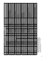
Modbus-RTU (RS485) BACnet IP / BACnet Ethernet / BACnet MSTP
Network Address: 1 Device Instance: 77000 (default)
Carel
Digital
Digital
Digital
Digital
Digital
Digital
Digital
Digital
Digital
Digital
Digital
Digital
Digital
Digital
Digital
Digital
Digital
Digital
Digital
Digital
Digital
Digital
Integer
Integer
Integer
Integer
Integer
Analog
Analog
Analog
Analog
Analog
Type
R
R
R
R
R
R
R
R
R
R
R
R
R/W
R/W
R/W
R
R
R
R
R
R
R
R
R
R
R
R
R/W
R
R
R
R
Sensor#3 out of range (cold coil leaving air temperature)
Sensor#2 out of range (supply air temperature)
Sensor#1 out of range (outside air temperature)
Supply air temperature low limit alarm
Compressor locked out alarm
Compressor trip alarm
Dirty filter alarm
Exhaust air proving alarm
Wheel rotation alarm
High Wheel pressure (high airflow or dirty wheel)
Supply air proving alarm
Global alarm indication (active when there is at least one alram)
Occupied/unoccupied command (0=occupied, 1=unoccpied)
Reset alams command
Unit start/stop command
Defrost mode status
Compressor #2 status
Compressor #1 ststus
Occupancy Status (0=Unoccupied, 1=Occupied)
Exhaust fan status
Supply fan status
Unit ON/Off
Hot Gas reheat output (0-100%)
Energy recovery wheel speed (5 speed) (defrost & economizier)
Cooling output (0-100%)
Heater output (0-100%)
Note 1
Temperature Set Pt (read/write) (###.#ºF) {Please refer to Controller IOM}
Room Air Temp (if Installed) (###.#ºF)
Cooling Coil air Temp (###.#ºF)
Supply Air Temp (###.#ºF)
Outside Air Temp (###.#ºF)
Read (Unit to BMS signal) Description
Write (BMS to Unit signal)
Date
Time
Notes:
Warranty
Greenheck warrants this equipment to be free from defects in material and workmanship for a period of one
year from the purchase date. The energy recovery wheel is warranted to be free from defects in material
and workmanshipfor a period of five years from the purchase date. Any units or parts which prove defective
during the warranty period will be replaced at our option when returned to our factory, transportation
prepaid.
Motors are warranted by the motor manufacturer for a period of one year. Should motors furnished by
Greenheck prove defective during this period, they should be returned to the nearest authorized motor
service station. Greenheck will not be responsible for any removal or installation costs.
As a result of our commitment to continuous improvement, Greenheck reserves the right to change
specifications without notice.
IOM DDC Controller
Rev. 1 February 2007
Copyright © 2007 Greenheck Fan Corp.